2007 ISUZU KB P190 oil
[x] Cancel search: oilPage 4435 of 6020
TRANSMISSION CONTROL SYSTEM (JR405E) 7A2-151
The transmission fluid temperature (TFT) sensor is part
of the harness assembly. The sensor is a variable
resistor and it measures the temperature of the
transmission fluid. When the TFT sensor is cold, the
sensor resistance is high. When the transmission fluid
temperature increases, the sensor resistance
decreases. With high sensor resistance, the TCM
detects a high voltage on the signal circuit. With lower
sensor resistance, the TCM detects a lower voltage on
the signal circuit.
If the fluid temperature increases to 135 °C (275 °F), the
TCM illuminates A/T Oil Temp lamp on the instrument
panel cluster. When the fluid temperature deceases
below 125 °C (257 °F), the lamp goes off.
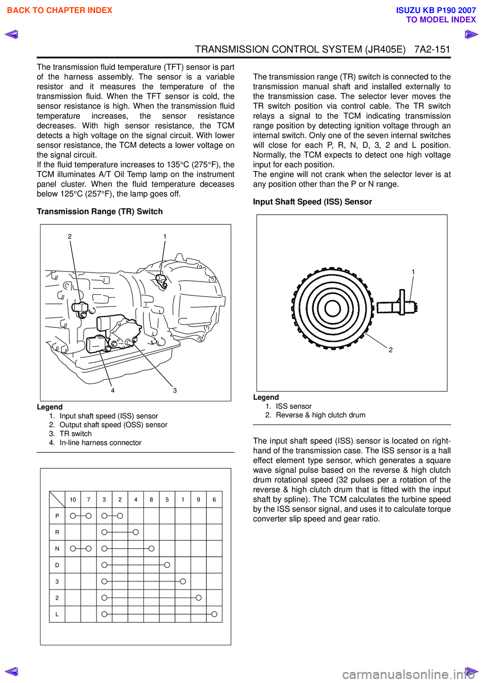
Transmission Range (TR) Switch
Legend 1. Input shaft speed (ISS) sensor
2. Output shaft speed (OSS) sensor
3. TR switch
4. In-line harness connector
The transmission range (TR) switch is connected to the
transmission manual shaft and installed externally to
the transmission case. The selector lever moves the
TR switch position via control cable. The TR switch
relays a signal to the TCM indicating transmission
range position by detecting ignition voltage through an
internal switch. Only one of the seven internal switches
will close for each P, R, N, D, 3, 2 and L position.
Normally, the TCM expects to detect one high voltage
input for each position.
The engine will not crank when the selector lever is at
any position other than the P or N range.
Input Shaft Speed (ISS) Sensor
Legend 1. ISS sensor
2. Reverse & high clutch drum
The input shaft speed (ISS) sensor is located on right-
hand of the transmission case. The ISS sensor is a hall
effect element type sensor, which generates a square
wave signal pulse based on the reverse & high clutch
drum rotational speed (32 pulses per a rotation of the
reverse & high clutch drum that is fitted with the input
shaft by spline). The TCM calculates the turbine speed
by the ISS sensor signal, and uses it to calculate torque
converter slip speed and gear ratio.
3
1
24
P
R
N
D
3
2
L
10732485196
1
2
BACK TO CHAPTER INDEX
TO MODEL INDEX
ISUZU KB P190 2007
Page 4437 of 6020
TRANSMISSION CONTROL SYSTEM (JR405E) 7A2-153
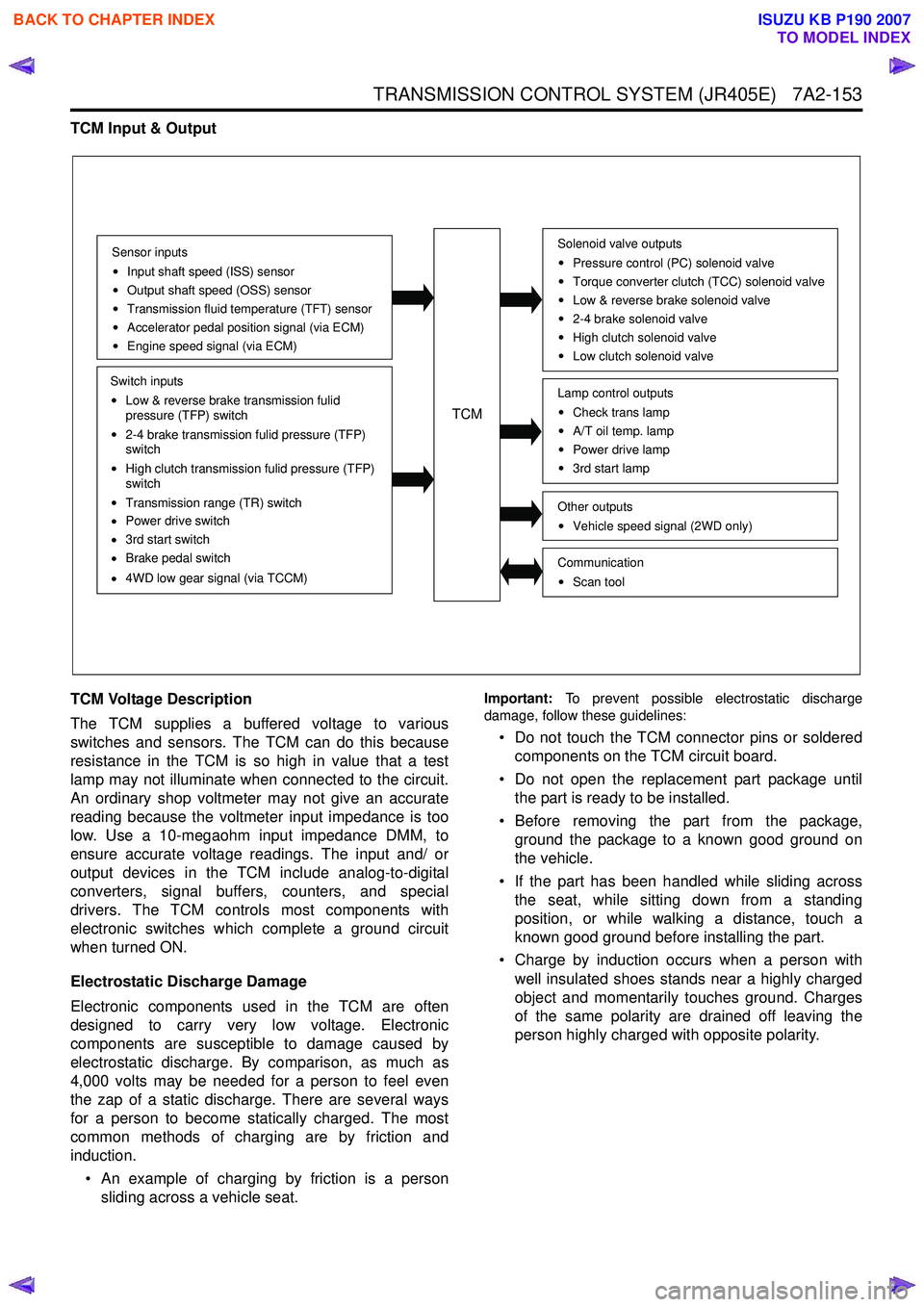
TCM Input & Output
TCM Voltage Description
The TCM supplies a buffered voltage to various
switches and sensors. The TCM can do this because
resistance in the TCM is so high in value that a test
lamp may not illuminate when connected to the circuit.
An ordinary shop voltmeter may not give an accurate
reading because the voltmeter input impedance is too
low. Use a 10-megaohm input impedance DMM, to
ensure accurate voltage readings. The input and/ or
output devices in the TCM include analog-to-digital
converters, signal buffers, counters, and special
drivers. The TCM controls most components with
electronic switches which complete a ground circuit
when turned ON.
Electrostatic Discharge Damage
Electronic components used in the TCM are often
designed to carry very low voltage. Electronic
components are susceptible to damage caused by
electrostatic discharge. By comparison, as much as
4,000 volts may be needed for a person to feel even
the zap of a static discharge. There are several ways
for a person to become statically charged. The most
common methods of charging are by friction and
induction.
• An example of charging by friction is a person sliding across a vehicle seat.
Important: To prevent possible electrostatic discharge
damage, follow these guidelines:
• Do not touch the TCM connector pins or soldered components on the TCM circuit board.
• Do not open the replacement part package until the part is ready to be installed.
• Before removing the part from the package, ground the package to a known good ground on
the vehicle.
• If the part has been handled while sliding across the seat, while sitting down from a standing
position, or while walking a distance, touch a
known good ground before installing the part.
• Charge by induction occurs when a person with well insulated shoes stands near a highly charged
object and momentarily touches ground. Charges
of the same polarity are drained off leaving the
person highly charged with opposite polarity.
Sensor inputs
Input shaft speed (ISS) sensor
Output shaft speed (OSS) sensor
Transmission fluid temperature (TFT) sensor
Accelerator pedal position signal (via ECM)
Engine speed signal (via ECM)
Switch inputs
Low & reverse brake transmission fulid
pressure (TFP) switch
2-4 brake transmission fulid pressure (TFP)
switch
High clutch transmission fulid pressure (TFP)
switch
Transmission range (TR) switch
Power drive switch
3rd start switch
Brake pedal switch
4WD low gear signal (via TCCM)
TCM
Solenoid valve outputs
Pressure control (PC) solenoid valve
Torque converter clutch (TCC) solenoid valve
Low & reverse brake solenoid valve
2-4 brake solenoid valve
High clutch solenoid valve
Low clutch solenoid valve
Other outputsVehicle speed signal (2WD only)
CommunicationScan tool
Lamp control outputsCheck trans lamp
A/T oil temp. lamp
Power drive lamp
3rd start lamp
BACK TO CHAPTER INDEX
TO MODEL INDEX
ISUZU KB P190 2007
Page 4439 of 6020
TRANSMISSION CONTROL SYSTEM (JR405E) 7A2-155
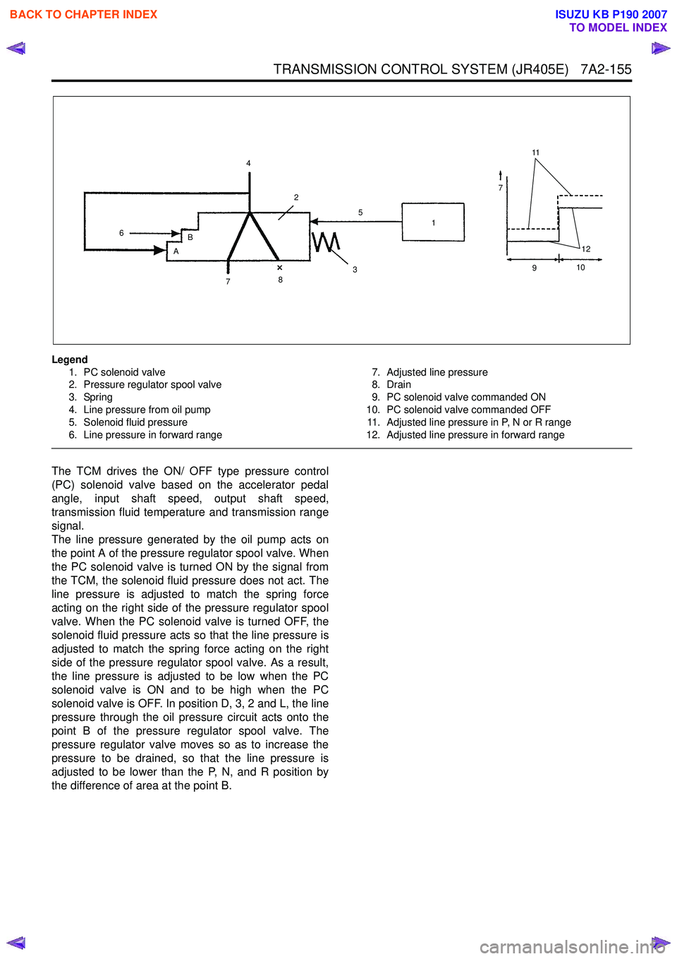
Legend1. PC solenoid valve
2. Pressure regulator spool valve
3. Spring
4. Line pressure from oil pump
5. Solenoid fluid pressure
6. Line pressure in forward range 7. Adjusted line pressure
8. Drain
9. PC solenoid valve commanded ON
10. PC solenoid valve commanded OFF 11. Adjusted line pressure in P, N or R range
12. Adjusted line pressure in forward range
The TCM drives the ON/ OFF type pressure control
(PC) solenoid valve based on the accelerator pedal
angle, input shaft speed, output shaft speed,
transmission fluid temperature and transmission range
signal.
The line pressure generated by the oil pump acts on
the point A of the pressure regulator spool valve. When
the PC solenoid valve is turned ON by the signal from
the TCM, the solenoid fluid pressure does not act. The
line pressure is adjusted to match the spring force
acting on the right side of the pressure regulator spool
valve. When the PC solenoid valve is turned OFF, the
solenoid fluid pressure acts so that the line pressure is
adjusted to match the spring force acting on the right
side of the pressure regulator spool valve. As a result,
the line pressure is adjusted to be low when the PC
solenoid valve is ON and to be high when the PC
solenoid valve is OFF. In position D, 3, 2 and L, the line
pressure through the oil pressure circuit acts onto the
point B of the pressure regulator spool valve. The
pressure regulator valve moves so as to increase the
pressure to be drained, so that the line pressure is
adjusted to be lower than the P, N, and R position by
the difference of area at the point B.
11
7
12
4
6 B
A 2
7 8 3 1
5
910
BACK TO CHAPTER INDEX
TO MODEL INDEX
ISUZU KB P190 2007
Page 4442 of 6020
7A2-158 TRANSMISSION CONTROL SYSTEM (JR405E)
The TCM controls the torque converter clutch (TCC)
solenoid valve based on the accelerator pedal angle,
input shaft speed, output shaft speed and transmission
fluid temperature.
Smooth lock up control is employed to engage or
disengage the TCC smoothly at the time of lock up On
or Off. When the TCM determines the TCC
engagement, the solenoid valve control duty cycle
(pulse width modulation [PWM]) signal is gradually
increased (5% to 95%) and the transmission fluid
between the TCC piston and torque converter front
cover is gradually drained. As a result, the TCC piston
is fitted slowly to the torque converter front cover under
fluid pressure securing smooth lock up engagement. The lock up control does not start when the
transmission fluid temperature is less than 20 °C (68 °F)
even though the vehicle is at the lock up control speed
area. The lock up control disengages when the
accelerator pedal angle is released.
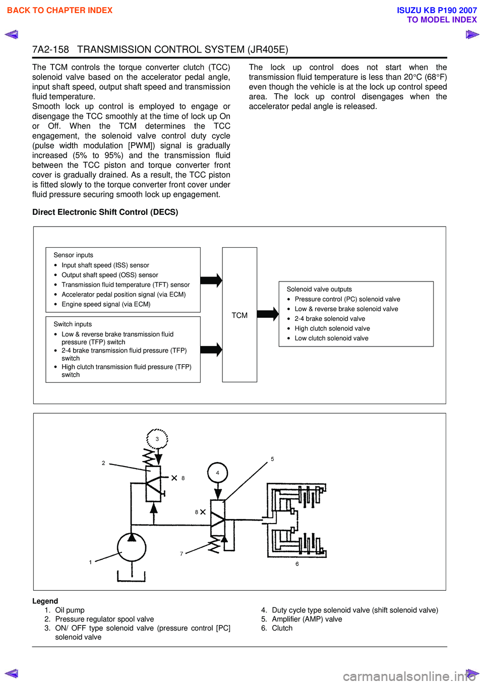
Direct Electronic Shift Control (DECS)
Legend 1. Oil pump
2. Pressure regulator spool valve
3. ON/ OFF type solenoid valve (pressure control [PC]
solenoid valve 4. Duty cycle type solenoid valve (shift solenoid valve)
5. Amplifier (AMP) valve
6. Clutch
Solenoid valve outputs
Pressure control (PC) solenoid valve
Low & reverse brake solenoid valve
2-4 brake solenoid valve
High clutch solenoid valve
Low clutch solenoid valve
TCM
Sensor inputsInput shaft speed (ISS) sensor
Output shaft speed (OSS) sensor
Transmission fluid temperature (TFT) sensor
Accelerator pedal position signal (via ECM)
Engine speed signal (via ECM)
Switch inputs
Low & reverse brake transmission fluid
pressure (TFP) switch
2-4 brake transmission fluid pressure (TFP)
switch
High clutch transmission fluid pressure (TFP)
switch
BACK TO CHAPTER INDEX
TO MODEL INDEX
ISUZU KB P190 2007
Page 4455 of 6020
ON-VEHICLE SERVICE (JR405E) 7A3-1
SECTION 7A3
ON-VEHICLE SERVICE (JR405E)
TABLE OF CONTENTS
PAGE
Description ................................................................................................................... ... 7A3 – 2
Automatic Transmission Fluid (ATF) ............................................................................ 7A3 – 2
ATF Level ..................................................................................................................... .... 7A3 – 2
ATF Change .................................................................................................................... . 7A3 – 3
Transmission Control Module (TCM) ............................................................................ 7A3 – 5
Inhibitor Switch .............................................................................................................. . 7A3 – 6
Speed Sensor .................................................................................................................. 7A3 – 8
Turbine Sensor ............................................................................................................... 7A3 – 9
Power and 3rd Start Switch ........................................................................................... 7A3 – 9
Select Lever .................................................................................................................. ... 7A3 –10
Shift Cable ................................................................................................................... .... 7A3 –13
Solenoids, Oil Pressure Switch and Oil Temperature Sensor .................................... 7A3 –16
Control Valve Assembly ................................................................................................. 7A3 –1 8
Flushing the Transmission Fluid Cooler and Line ...................................................... 7A3 –19
Transmission Assembly ................................................................................................. 7A3 –20
Special Service Tool ....................................................................................................... 7A 3 –23
BACK TO CHAPTER INDEX
TO MODEL INDEX
ISUZU KB P190 2007
Page 4457 of 6020
ON-VEHICLE SERVICE (JR405E) 7A3-3
Cold Level
The vehicle must not have been driven so that the
temperature reaches around 20 °C (68 °F) before the
cold level check is made.
1. Park the vehicle on a level surface.
2. Apply the parking brake firmly.
3. Start the engine and allow it to warm up.
The engine coolant temperature gauge needle should be midway between the “C” mark and “H”
mark.
4. Let the engine run at idle.
Move the select lever slowly through all the gea
r
ranges.
Stop in each range just long enough for the transmission to engage.
5. Return the select lever either “P” or “N”.
6. Remove the ATF level dipstick.
7. W ipe the dipstick clean with a paper towel.
8. Reinsert the dipstick and wait several seconds.
9. Remove the dipstick.
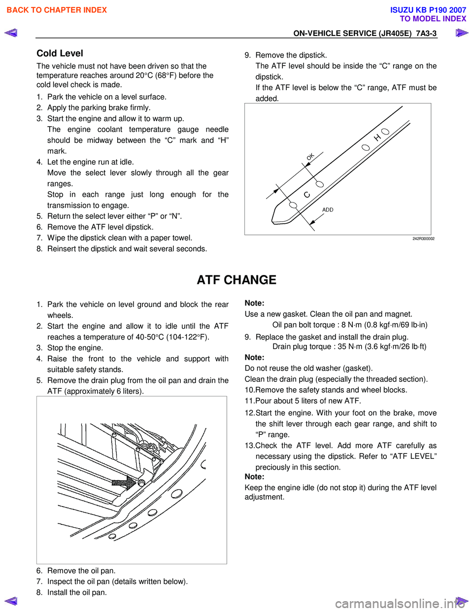
The ATF level should be inside the “C” range on the dipstick.
If the ATF level is below the “C” range, ATF must be added.
242R300002
ATF CHANGE
1. Park the vehicle on level ground and block the rear
wheels.
2. Start the engine and allow it to idle until the ATF reaches a temperature of 40-50 °C (104-122 °F).
3. Stop the engine.
4. Raise the front to the vehicle and support with suitable safety stands.
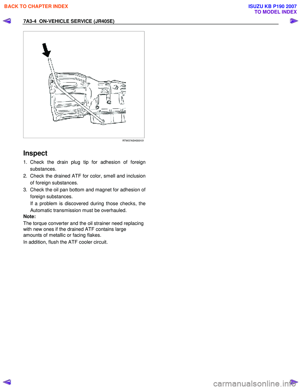
5. Remove the drain plug from the oil pan and drain the ATF (approximately 6 liters).
6. Remove the oil pan.
7. Inspect the oil pan (details written below).
8. Install the oil pan.
Note:
Use a new gasket. Clean the oil pan and magnet.
Oil pan bolt torque : 8 N ⋅m (0.8 kgf ⋅m/69 lb ⋅in)
9. Replace the gasket and install the drain plug.
Drain plug torque : 35 N ⋅m (3.6 kgf ⋅m/26 lb ⋅ft)
Note:
Do not reuse the old washer (gasket).
Clean the drain plug (especially the threaded section).
10.Remove the safety stands and wheel blocks.
11.Pour about 5 liters of new ATF.
12. Start the engine. W ith your foot on the brake, move the shift lever through each gear range, and shift to
“P” range.
13.Check the ATF level. Add more ATF carefully as necessary using the dipstick. Refer to “ATF LEVEL”
preciously in this section.
Note:
Keep the engine idle (do not stop it) during the ATF level
adjustment.
BACK TO CHAPTER INDEX
TO MODEL INDEX
ISUZU KB P190 2007
Page 4458 of 6020
7A3-4 ON-VEHICLE SERVICE (JR405E)
RTW 07ASH000101
Inspect
1. Check the drain plug tip for adhesion of foreign
substances.
2. Check the drained ATF for color, smell and inclusion of foreign substances.
3. Check the oil pan bottom and magnet for adhesion o
f
foreign substances.
If a problem is discovered during those checks, the Automatic transmission must be overhauled.
Note:
The torque converter and the oil strainer need replacing
with new ones if the drained ATF contains large
amounts of metallic or facing flakes.
In addition, flush the ATF cooler circuit.
BACK TO CHAPTER INDEX
TO MODEL INDEX
ISUZU KB P190 2007
Page 4470 of 6020
7A3-16 ON-VEHICLE SERVICE (JR405E)
SOLENOIDS, OIL PRESSURE SWITCH AND OIL TEMPERATURE
SENSOR
244L300003
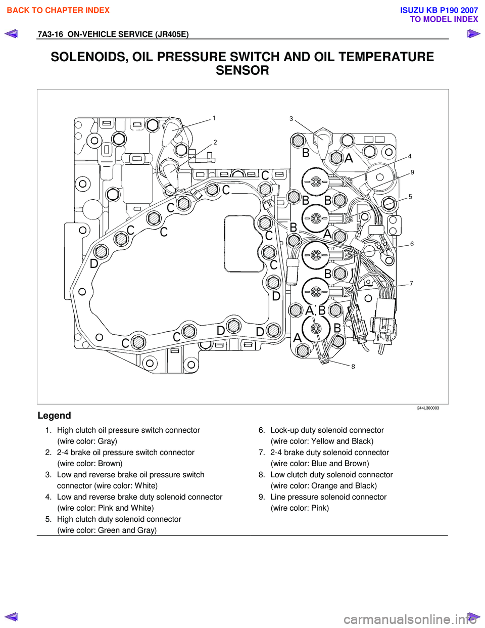
Legend
1. High clutch oil pressure switch connector
(wire color: Gray)
2. 2-4 brake oil pressure switch connector
(wire color: Brown)
3. Low and reverse brake oil pressure switch connector (wire color: W hite)
4. Low and reverse brake duty solenoid connector
(wire color: Pink and W hite)
5. High clutch duty solenoid connector
(wire color: Green and Gray)
6. Lock-up duty solenoid connector
(wire color: Yellow and Black)
7. 2-4 brake duty solenoid connector
(wire color: Blue and Brown)
8. Low clutch duty solenoid connector
(wire color: Orange and Black)
9. Line pressure solenoid connector
(wire color: Pink)
BACK TO CHAPTER INDEX
TO MODEL INDEX
ISUZU KB P190 2007