2007 ISUZU KB P190 Circuit
[x] Cancel search: CircuitPage 4305 of 6020
TRANSMISSION CONTROL SYSTEM (JR405E) 7A2-21
Diagnostic Information and Procedures
Diagnostic Starting Point - Transmission Controls
Begin the system diagnosis with Diagnostic System
Check - Transmission Controls. The Diagnostic System
Check - Transmission Controls will provide the
following information:
• The identification of the control modules which command the system.
• The ability of the control modules to communicate through the serial data circuit.
• The identification of any stored diagnostic trouble codes (DTCs) and the their statuses.
The use of the Diagnostic System Check -
Transmission Controls will identify the correct
procedure for diagnosing the system and where the
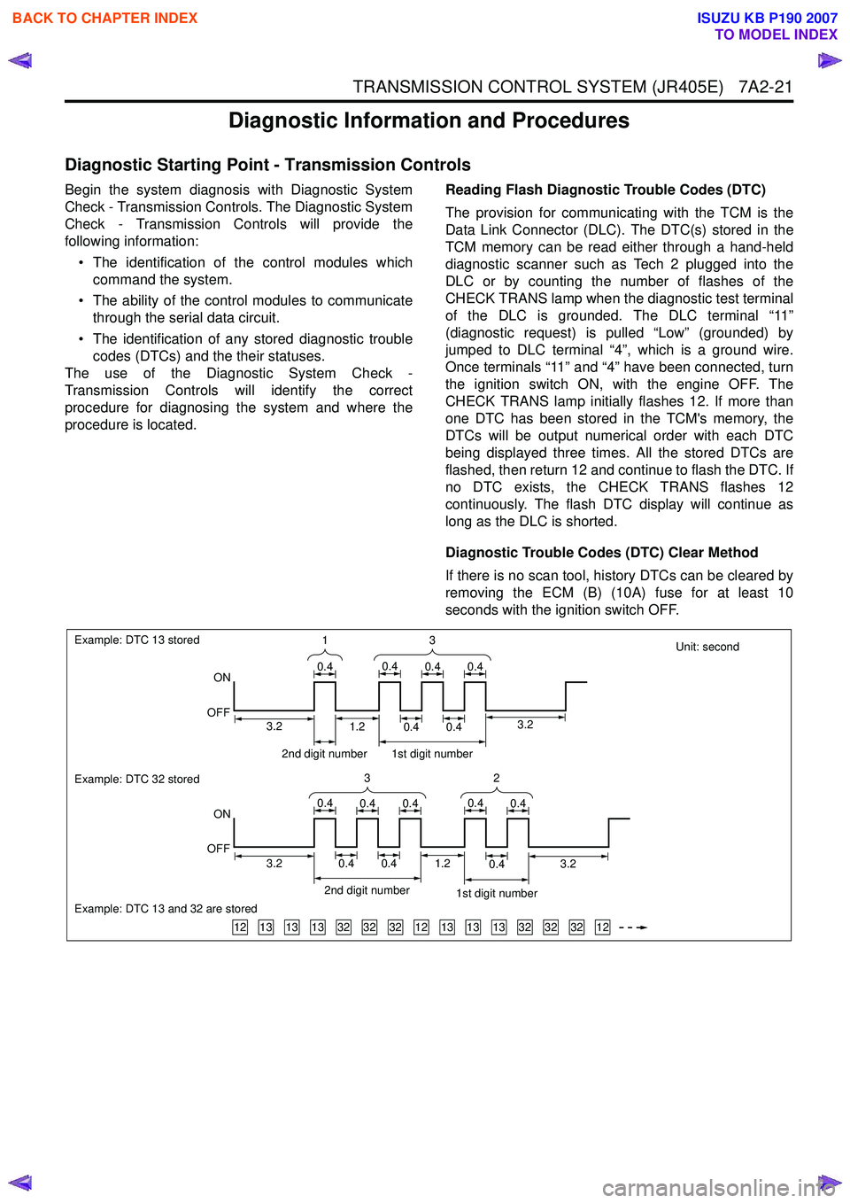
procedure is located. Reading Flash Diagnostic Trouble Codes (DTC)
The provision for communicating with the TCM is the
Data Link Connector (DLC). The DTC(s) stored in the
TCM memory can be read either through a hand-held
diagnostic scanner such as Tech 2 plugged into the
DLC or by counting the number of flashes of the
CHECK TRANS lamp when the diagnostic test terminal
of the DLC is grounded. The DLC terminal “11”
(diagnostic request) is pulled “Low” (grounded) by
jumped to DLC terminal “4”, which is a ground wire.
Once terminals “11” and “4” have been connected, turn
the ignition switch ON, with the engine OFF. The
CHECK TRANS lamp initially flashes 12. If more than
one DTC has been stored in the TCM's memory, the
DTCs will be output numerical order with each DTC
being displayed three times. All the stored DTCs are
flashed, then return 12 and continue to flash the DTC. If
no DTC exists, the CHECK TRANS flashes 12
continuously. The flash DTC display will continue as
long as the DLC is shorted.
Diagnostic Trouble Codes (DTC) Clear Method
If there is no scan tool, history DTCs can be cleared by
removing the ECM (B) (10A) fuse for at least 10
seconds with the ignition switch OFF.
Unit: second
131313323232121313133232321212
Example: DTC 13 stored
ON
OFF
Example: DTC 32 stored
Example: DTC 13 and 32 are stored
ON
OFF 3
1
0.40.40.40.4
32
0.40.40.40.40.4
2nd digit number1st digit number
3.23.20.40.40.41.2
2nd digit number 1st digit number
0.40.41.23.23.2
BACK TO CHAPTER INDEX
TO MODEL INDEX
ISUZU KB P190 2007
Page 4306 of 6020
7A2-22 TRANSMISSION CONTROL SYSTEM (JR405E)
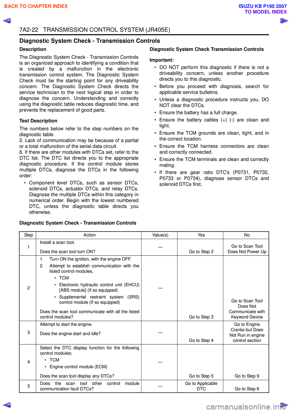
Diagnostic System Check - Transmission Controls
Description
The Diagnostic System Check - Transmission Controls
is an organized approach to identifying a condition that
is created by a malfunction in the electronic
transmission control system. The Diagnostic System
Check must be the starting point for any driveability
concern. The Diagnostic System Check directs the
service technician to the next logical step in order to
diagnose the concern. Understanding and correctly
using the diagnostic table reduces diagnostic time, and
prevents the replacement of good parts.
Test Description
The numbers below refer to the step numbers on the
diagnostic table.
2. Lack of communication may be because of a partial
or a total malfunction of the serial data circuit.
8. If there are other modules with DTCs set, refer to the
DTC list. The DTC list directs you to the appropriate
diagnostic procedure. If the control module stores
multiple DTCs, diagnose the DTCs in the following
order:
• Component level DTCs, such as sensor DTCs, solenoid DTCs, actuator DTCs, and relay DTCs.
Diagnose the multiple DTCs within this category in
numerical order. Begin with the lowest numbered
DTC, unless the diagnostic table directs you
otherwise. Diagnostic System Check Transmission Controls
Important: • DO NOT perform this diagnostic if there is not a driveability concern, unless another procedure
directs you to this diagnostic.
• Before you proceed with diagnosis, search for applicable service bulletins.
• Unless a diagnostic procedure instructs you, DO NOT clear the DTCs.
• Ensure the battery has a full charge.
• Ensure the battery cables (+) (-) are clean and tight.
• Ensure the TCM grounds are clean, tight, and in the correct location.
• Ensure the TCM harness connectors are clean and correctly connected.
• Ensure the TCM terminals are clean and correctly mating.
• If there are gear ratio DTC's (P0731, P0732, P0733 or P0734), diagnose sensor DTCs and
solenoid DTCs first.
Diagnostic System Check - Transmission Controls
Step Action Value(s)Yes No
1 Install a scan tool.
Does the scan tool turn ON? —
Go to Step 2 Go to Scan Tool
Does Not Power Up
2 1. Turn ON the ignition, with the engine OFF.
2. Attempt to establish communication with the listed control modules.
•TCM
• Electronic hydraulic control unit (EHCU) [ABS module] (If so equipped)
• Supplemental restraint system (SRS) control module (If so equipped)
Does the scan tool communicate with all the listed
control modules? —
Go to Step 3 Go to Scan Tool
Does Not
Communicate with Keyword Device
3 Attempt to start the engine.
Does the engine start and idle? —
Go to Step 4 Go to Engine
Cranks but Does
Not Run in engine control section
4 Select the DTC display function for the following
control modules:
•TCM
• Engine control module (ECM)
Does the scan tool display any DTCs? —
Go to Step 5 Go to Step 9
5 Does the scan tool other control module
communication fault DTCs? —Go to Applicable
DTC Go to Step 6
BACK TO CHAPTER INDEX
TO MODEL INDEX
ISUZU KB P190 2007
Page 4309 of 6020
TRANSMISSION CONTROL SYSTEM (JR405E) 7A2-25
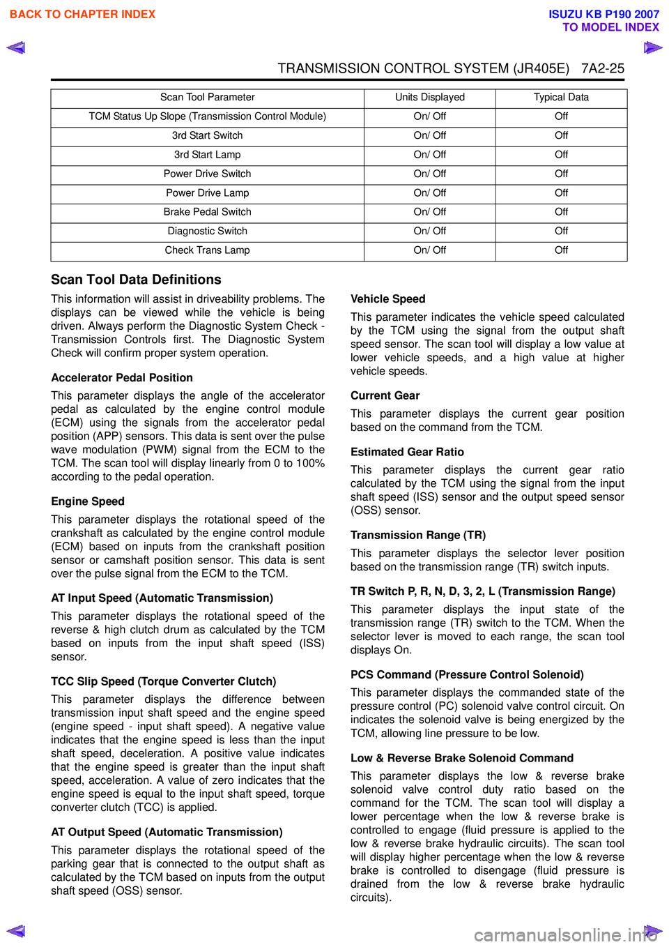
Scan Tool Data Definitions
This information will assist in driveability problems. The
displays can be viewed while the vehicle is being
driven. Always perform the Diagnostic System Check -
Transmission Controls first. The Diagnostic System
Check will confirm proper system operation.
Accelerator Pedal Position
This parameter displays the angle of the accelerator
pedal as calculated by the engine control module
(ECM) using the signals from the accelerator pedal
position (APP) sensors. This data is sent over the pulse
wave modulation (PWM) signal from the ECM to the
TCM. The scan tool will display linearly from 0 to 100%
according to the pedal operation.
Engine Speed
This parameter displays the rotational speed of the
crankshaft as calculated by the engine control module
(ECM) based on inputs from the crankshaft position
sensor or camshaft position sensor. This data is sent
over the pulse signal from the ECM to the TCM.
AT Input Speed (Automatic Transmission)
This parameter displays the rotational speed of the
reverse & high clutch drum as calculated by the TCM
based on inputs from the input shaft speed (ISS)
sensor.
TCC Slip Speed (Torque Converter Clutch)
This parameter displays the difference between
transmission input shaft speed and the engine speed
(engine speed - input shaft speed). A negative value
indicates that the engine speed is less than the input
shaft speed, deceleration. A positive value indicates
that the engine speed is greater than the input shaft
speed, acceleration. A value of zero indicates that the
engine speed is equal to the input shaft speed, torque
converter clutch (TCC) is applied.
AT Output Speed (Automatic Transmission)
This parameter displays the rotational speed of the
parking gear that is connected to the output shaft as
calculated by the TCM based on inputs from the output
shaft speed (OSS) sensor. Vehicle Speed
This parameter indicates the vehicle speed calculated
by the TCM using the signal from the output shaft
speed sensor. The scan tool will display a low value at
lower vehicle speeds, and a high value at higher
vehicle speeds.
Current Gear
This parameter displays the current gear position
based on the command from the TCM.
Estimated Gear Ratio
This parameter displays the current gear ratio
calculated by the TCM using the signal from the input
shaft speed (ISS) sensor and the output speed sensor
(OSS) sensor.
Transmission Range (TR)
This parameter displays the selector lever position
based on the transmission range (TR) switch inputs.
TR Switch P, R, N, D, 3, 2, L (Transmission Range)
This parameter displays the input state of the
transmission range (TR) switch to the TCM. When the
selector lever is moved to each range, the scan tool
displays On.
PCS Command (Pressure Control Solenoid)
This parameter displays the commanded state of the
pressure control (PC) solenoid valve control circuit. On
indicates the solenoid valve is being energized by the
TCM, allowing line pressure to be low.
Low & Reverse Brake Solenoid Command
This parameter displays the low & reverse brake
solenoid valve control duty ratio based on the
command for the TCM. The scan tool will display a
lower percentage when the low & reverse brake is
controlled to engage (fluid pressure is applied to the
low & reverse brake hydraulic circuits). The scan tool
will display higher percentage when the low & reverse
brake is controlled to disengage (fluid pressure is
drained from the low & reverse brake hydraulic
circuits).
TCM Status Up Slope (Transmission Control Module) On/ OffOff
3rd Start Switch On/ OffOff
3rd Start Lamp On/ OffOff
Power Drive Switch On/ OffOff
Power Drive Lamp On/ OffOff
Brake Pedal Switch On/ OffOff
Diagnostic Switch On/ OffOff
Check Trans Lamp On/ OffOff
Scan Tool Parameter
Units DisplayedTypical Data
BACK TO CHAPTER INDEX
TO MODEL INDEX
ISUZU KB P190 2007
Page 4310 of 6020
7A2-26 TRANSMISSION CONTROL SYSTEM (JR405E)
Low & Reverse Brake Pressure Switch
This parameter displays the input state of the low &
reverse brake transmission fluid pressure (TFP) switch
to the TCM. When the low & reverse brake fluid
pressure is generated, the scan tool displays On.
2-4 Brake Solenoid Command
This parameter displays the 2-4 brake solenoid valve
control duty ratio based on the command from the
TCM. The scan tool will display a lower percentage
when the 2-4 brake is controlled to engage (fluid
pressure is applied to the 2-4 brake hydraulic circuits).
The scan tool will display higher percentage when the
2-4 brake is controlled to disengage (fluid pressure is
drained from the 2-4 brake hydraulic circuits).
2-4 Brake Pressure Switch
This parameter displays the input state of the 2-4 brake
transmission fluid pressure (TFP) switch to the TCM.
When the 2-4 brake fluid pressure is generated, the
scan tool displays On.
High Clutch Solenoid Command
This parameter displays the high clutch solenoid valve
control duty ratio based on the command from the
TCM. The scan tool will display a lower percentage
when the high clutch is controlled to engage (fluid
pressure is applied to the high clutch hydraulic circuits).
The scan tool will display higher percentage when the
high clutch is controlled to disengage (fluid pressure is
drained from the high clutch hydraulic circuits).
High Clutch Pressure Switch
This parameter displays the input state of the high
clutch transmission fluid pressure (TFP) switch to the
TCM. When the high clutch fluid pressure is generated,
the scan tool displays On.
Low Clutch Solenoid Command
This parameter displays the low clutch solenoid valve
control duty ratio based on the command from the
TCM. The scan tool will display a lower percentage
when the low clutch is controlled to engage (fluid
pressure is applied to the low clutch hydraulic circuits).
The scan tool will display higher percentage when the
low clutch is controlled to disengage (fluid pressure is
drained from the low clutch hydraulic circuits).
TCC Solenoid (Torque Converter Clutch)
This parameter displays the torque converter clutch
(TCC) control duty ratio based on the command from
the TCM. The scan tool will display a lower percentage
when the TCC is controlled to disengage (fluid
pressure is drained from the TCC release hydraulic
circuits). The scan tool will display higher percentage
when the TCC is controlled to engage (fluid pressure is
applied to the TCC apply hydraulic circuits). Transmission Fluid Temperature
This parameter displays the temperature of the
automatic transmission fluid (ATF) temperature as
calculated by the TCM using the signal from the
transmission fluid temperature (TFT) sensor. The scan
tool will display a low temperature when the signal
voltage is high, and a high temperature when the signal
voltage is low.
Transmission Oil Temperature Lamp
This parameter displays the commanded state of the
transmission oil temperature lamp control circuit. The
lamp should be On when the scan tool indicates
command On.
TCM Status Temp. (Temperature Transmission
Control Module)
This parameter displays the commanded state of the
high temperature mode shift map. On indicates the
transmission fluid temperature is high and the high
temperature mode is selected to prevent an
overheating.
4 Wheel Drive Low
This parameter displays the input state of the 4WD low
gear signal from the transfer case control module
(TCCM). When the 4L mode is selected, the scan tool
displays On.
TCM Status Transfer (Transmission Control
Module)
This parameter displays the commanded state of the
shift map that is based on the transfer case position.
High indicates the high mode (2H or 4H) is inputted
from the transfer case control module (TCCM). Low
indicates the low mode (4L) is inputted from the TCCM.
TCM Status Down Slope (Transmission Control
Module)
This parameter displays the commanded state of the
down slope mode shift map. On indicates the down
slope mode is selected under certain driving conditions.
TCM Status Up Slope (Transmission Control
Module)
This parameter displays the commanded state of the
up slope mode shift map. On indicates the up slope
mode is selected under certin driving conditions.
3rd Start Switch
This parameter displays the input state of the 3rd start
switch to the TCM. When the switch is pressed, the
scan tool displays On.
3rd Start Lamp
This parameter displays the commanded state of the
3rd start lamp control circuit. The lamp should be On
when the scan tool indicates command On.
BACK TO CHAPTER INDEX
TO MODEL INDEX
ISUZU KB P190 2007
Page 4311 of 6020
TRANSMISSION CONTROL SYSTEM (JR405E) 7A2-27
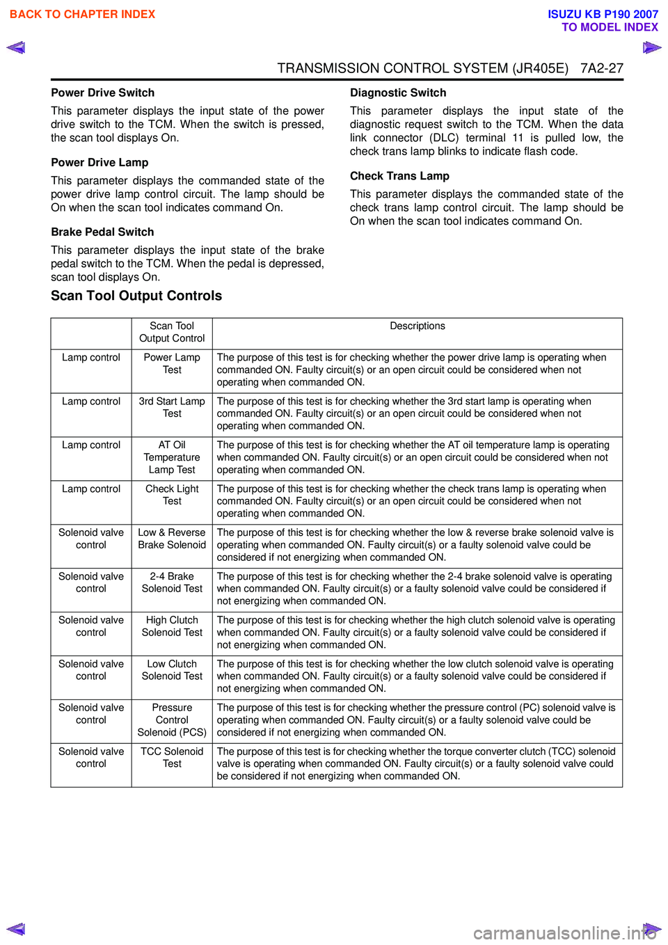
Power Drive Switch
This parameter displays the input state of the power
drive switch to the TCM. When the switch is pressed,
the scan tool displays On.
Power Drive Lamp
This parameter displays the commanded state of the
power drive lamp control circuit. The lamp should be
On when the scan tool indicates command On.
Brake Pedal Switch
This parameter displays the input state of the brake
pedal switch to the TCM. When the pedal is depressed,
scan tool displays On. Diagnostic Switch
This parameter displays the input state of the
diagnostic request switch to the TCM. When the data
link connector (DLC) terminal 11 is pulled low, the
check trans lamp blinks to indicate flash code.
Check Trans Lamp
This parameter displays the commanded state of the
check trans lamp control circuit. The lamp should be
On when the scan tool indicates command On.
Scan Tool Output Controls
Scan Tool
Output Control Descriptions
Lamp control Power Lamp Te s tThe purpose of this test is for checking whether the power drive lamp is operating when
commanded ON. Faulty circuit(s) or an open circuit could be considered when not
operating when commanded ON.
Lamp control 3rd Start Lamp Te s t The purpose of this test is for checking whether the 3rd start lamp is operating when
commanded ON. Faulty circuit(s) or an open circuit could be considered when not
operating when commanded ON.
Lamp control AT Oil Temperature
Lamp Test The purpose of this test is for checking whether the AT oil temperature lamp is operating
when commanded ON. Faulty circuit(s) or an open circuit could be considered when not
operating when commanded ON.
Lamp control Check Light Te s t The purpose of this test is for checking whether the check trans lamp is operating when
commanded ON. Faulty circuit(s) or an open circuit could be considered when not
operating when commanded ON.
Solenoid valve control Low & Reverse
Brake Solenoid The purpose of this test is for checking whether the low & reverse brake solenoid valve is
operating when commanded ON. Faulty circuit(s) or a faulty solenoid valve could be
considered if not energizing when commanded ON.
Solenoid valve control 2-4 Brake
Solenoid Test The purpose of this test is for checking whether the 2-4 brake solenoid valve is operating
when commanded ON. Faulty circuit(s) or a faulty solenoid valve could be considered if
not energizing when commanded ON.
Solenoid valve control High Clutch
Solenoid Test The purpose of this test is for checking whether the high clutch solenoid valve is operating
when commanded ON. Faulty circuit(s) or a faulty solenoid valve could be considered if
not energizing when commanded ON.
Solenoid valve control Low Clutch
Solenoid Test The purpose of this test is for checking whether the low clutch solenoid valve is operating
when commanded ON. Faulty circuit(s) or a faulty solenoid valve could be considered if
not energizing when commanded ON.
Solenoid valve control Pressure
Control
Solenoid (PCS) The purpose of this test is for checking whether the pressure control (PC) solenoid valve is
operating when commanded ON. Faulty circuit(s) or a faulty solenoid valve could be
considered if not energizing when commanded ON.
Solenoid valve control TCC Solenoid
Te s t The purpose of this test is for checking whether the torque converter clutch (TCC) solenoid
valve is operating when commanded ON. Faulty circuit(s) or a faulty solenoid valve could
be considered if not energizing when commanded ON.
BACK TO CHAPTER INDEX
TO MODEL INDEX
ISUZU KB P190 2007
Page 4312 of 6020
7A2-28 TRANSMISSION CONTROL SYSTEM (JR405E)
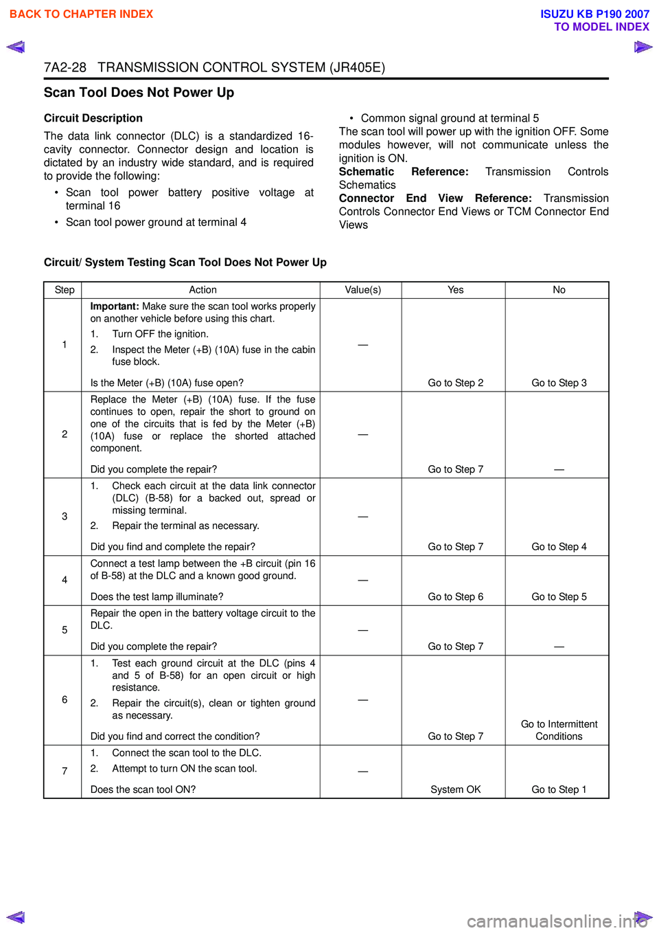
Scan Tool Does Not Power Up
Circuit Description
The data link connector (DLC) is a standardized 16-
cavity connector. Connector design and location is
dictated by an industry wide standard, and is required
to provide the following:
• Scan tool power battery positive voltage at terminal 16
• Scan tool power ground at terminal 4 • Common signal ground at terminal 5
The scan tool will power up with the ignition OFF. Some
modules however, will not communicate unless the
ignition is ON.
Schematic Reference: Transmission Controls
Schematics
Connector End View Reference: Transmission
Controls Connector End Views or TCM Connector End
Views
Circuit/ System Testing Scan Tool Does Not Power Up
Step Action Value(s)Yes No
1 Important:
Make sure the scan tool works properly
on another vehicle before using this chart.
1. Turn OFF the ignition.
2. Inspect the Meter (+B) (10A) fuse in the cabin fuse block.
Is the Meter (+B) (10A) fuse open? —
Go to Step 2 Go to Step 3
2 Replace the Meter (+B) (10A) fuse. If the fuse
continues to open, repair the short to ground on
one of the circuits that is fed by the Meter (+B)
(10A) fuse or replace the shorted attached
component.
Did you complete the repair? —
Go to Step 7 —
3 1. Check each circuit at the data link connector
(DLC) (B-58) for a backed out, spread or
missing terminal.
2. Repair the terminal as necessary.
Did you find and complete the repair? —
Go to Step 7 Go to Step 4
4 Connect a test lamp between the +B circuit (pin 16
of B-58) at the DLC and a known good ground.
Does the test lamp illuminate? —
Go to Step 6 Go to Step 5
5 Repair the open in the battery voltage circuit to the
DLC.
Did you complete the repair? —
Go to Step 7 —
6 1. Test each ground circuit at the DLC (pins 4
and 5 of B-58) for an open circuit or high
resistance.
2. Repair the circuit(s), clean or tighten ground as necessary.
Did you find and correct the condition? —
Go to Step 7 Go to Intermittent
Conditions
7 1. Connect the scan tool to the DLC.
2. Attempt to turn ON the scan tool.
Does the scan tool ON? —
System OK Go to Step 1
BACK TO CHAPTER INDEX
TO MODEL INDEX
ISUZU KB P190 2007
Page 4313 of 6020
![ISUZU KB P190 2007 Workshop Repair Manual TRANSMISSION CONTROL SYSTEM (JR405E) 7A2-29
Scan Tool Does Not Communicate with Keyword Device
Circuit Description
The TCM, electronic hydraulic control unit (EHCU)
[ABS module] and supplemental r ISUZU KB P190 2007 Workshop Repair Manual TRANSMISSION CONTROL SYSTEM (JR405E) 7A2-29
Scan Tool Does Not Communicate with Keyword Device
Circuit Description
The TCM, electronic hydraulic control unit (EHCU)
[ABS module] and supplemental r](/manual-img/61/57177/w960_57177-4312.png)
TRANSMISSION CONTROL SYSTEM (JR405E) 7A2-29
Scan Tool Does Not Communicate with Keyword Device
Circuit Description
The TCM, electronic hydraulic control unit (EHCU)
[ABS module] and supplemental restraint system
(SRS) control module all communicate with the scan
tool over the Keyword serial data link.
Diagnostic Aids
The following conditions will cause a loss of Keyword
serial data communication between the scan tool and
the TCM.
• A Keyword serial data circuit open • A Keyword serial data circuit shorted to ground
• A Keyword serial data circuit shorted to voltage
• An internal condition within a module or connector on the Keyword serial data circuit, that causes a
short to voltage or ground to the Keyword serial
data circuit
Schematic Reference: Transmission Controls
Schematics
Connector End View Reference: Transmission
Controls Connector End Views or TCM Connector End
Views
Circuit/ System Testing Scan Tool Does Not Communicate with Keyward Device
Step Action Value(s)Yes No
1 Did you perform the Diagnostic System Check -
Engine Controls? —
Go to Step 2 Go to Diagnostic
System Check - Transmission Controls
2 1. Install a scan tool.
2. Turn ON the ignition, with the engine OFF.
3. Attempt to establish communication with the listed control modules.
•TCM
• Electronic hydraulic control unit (EHCU) [ABS module] (If so equipped)
• Supplemental restraint system (SRS) control module (If so equipped)
Does the scan tool communicate with any of the
listed control modules? —
Go to Step 3 Go to Step 7
3 Does the scan tool communicate with the TCM?
—Go to Step 4 Go to Lost
Communication with
The Transmission Control Module (TCM)
4 Notice:
If no ABS is installed, skip to Step 5.
Does the scan tool communicate with the EHCU? —
Go to Step 5 Go to Diagnostic
System Check - Anti-lock Brake Controls
5 Notice:
If no SRS is installed, skip to Step 6.
Does the scan tool communicate with the SRS
control module? —
Go to Step 6 Go to Diagnostic
System Check -SRS Controls
6 Test the Keyword serial data circuit for an
intermittently short to ground or intermittently short
to voltage. Then, test the Keyword serial data
circuit for an intermittently open (based on which
control module did not communicate) at the
connection in the circuit.
Did you find and correct the condition? —
Go to Step 15 System OK
7 1. Inspect for an intermittent, for a poor
connection and for corrosion at the data link
connector (DLC) (pin 7 of B-58).
2. Repair the connection(s) as necessary.
Did you find and correct the condition? —
Go to Step 15 Go to Step 8
BACK TO CHAPTER INDEX
TO MODEL INDEX
ISUZU KB P190 2007
Page 4314 of 6020
7A2-30 TRANSMISSION CONTROL SYSTEM (JR405E)
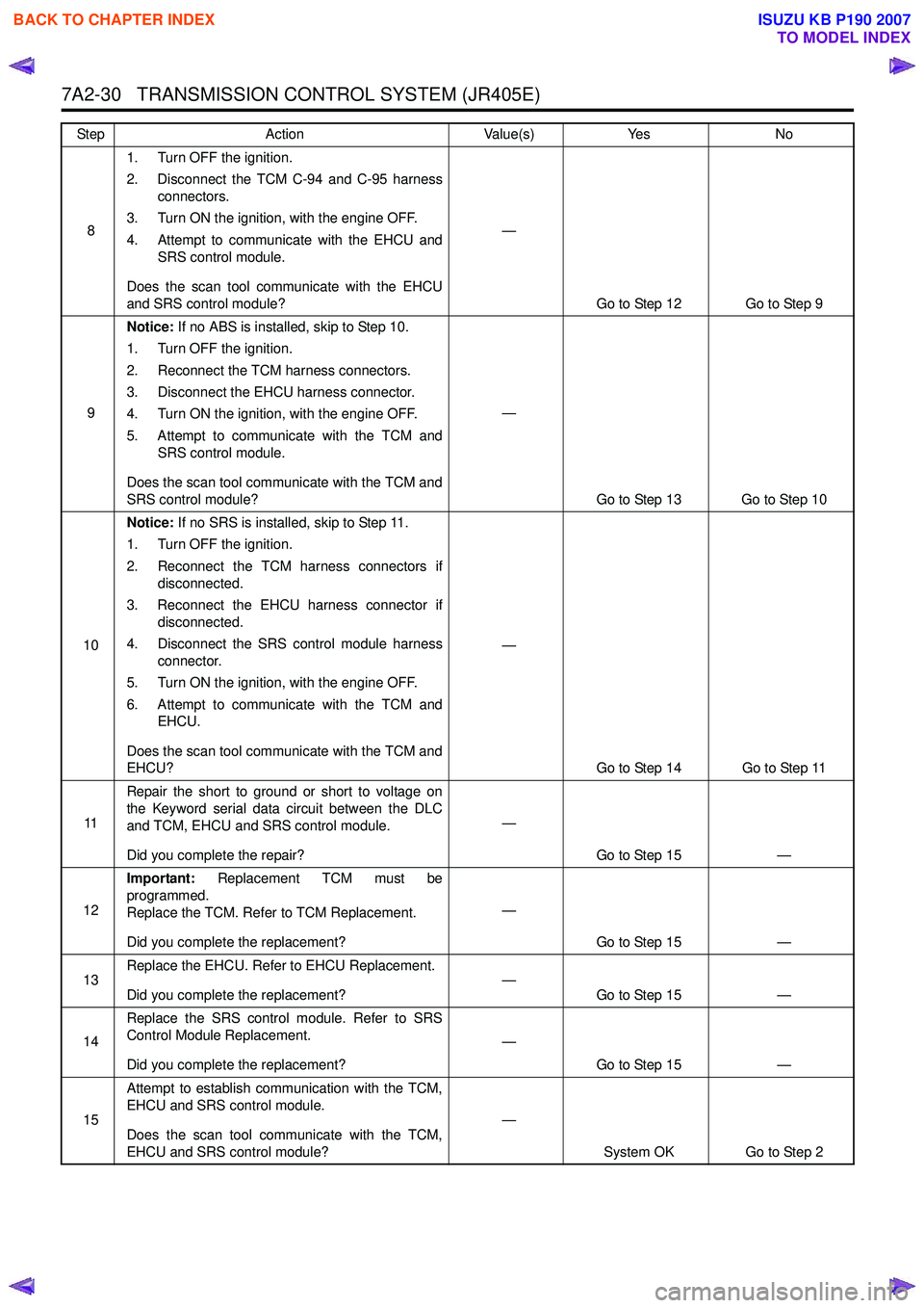
81. Turn OFF the ignition.
2. Disconnect the TCM C-94 and C-95 harness connectors.
3. Turn ON the ignition, with the engine OFF.
4. Attempt to communicate with the EHCU and SRS control module.
Does the scan tool communicate with the EHCU
and SRS control module? —
Go to Step 12 Go to Step 9
9 Notice:
If no ABS is installed, skip to Step 10.
1. Turn OFF the ignition.
2. Reconnect the TCM harness connectors.
3. Disconnect the EHCU harness connector.
4. Turn ON the ignition, with the engine OFF.
5. Attempt to communicate with the TCM and SRS control module.
Does the scan tool communicate with the TCM and
SRS control module? —
Go to Step 13 Go to Step 10
10 Notice:
If no SRS is installed, skip to Step 11.
1. Turn OFF the ignition.
2. Reconnect the TCM harness connectors if disconnected.
3. Reconnect the EHCU harness connector if disconnected.
4. Disconnect the SRS control module harness connector.
5. Turn ON the ignition, with the engine OFF.
6. Attempt to communicate with the TCM and EHCU.
Does the scan tool communicate with the TCM and
EHCU? —
Go to Step 14 Go to Step 11
11 Repair the short to ground or short to voltage on
the Keyword serial data circuit between the DLC
and TCM, EHCU and SRS control module.
Did you complete the repair? —
Go to Step 15 —
12 Important:
Replacement TCM must be
programmed.
Replace the TCM. Refer to TCM Replacement.
Did you complete the replacement? —
Go to Step 15 —
13 Replace the EHCU. Refer to EHCU Replacement.
Did you complete the replacement? —
Go to Step 15 —
14 Replace the SRS control module. Refer to SRS
Control Module Replacement.
Did you complete the replacement? —
Go to Step 15 —
15 Attempt to establish communication with the TCM,
EHCU and SRS control module.
Does the scan tool communicate with the TCM,
EHCU and SRS control module? —
System OK Go to Step 2
Step
Action Value(s)Yes No
BACK TO CHAPTER INDEX
TO MODEL INDEX
ISUZU KB P190 2007