2007 ISUZU KB P190 Circuit
[x] Cancel search: CircuitPage 4084 of 6020
7A2-118 TRANSMISSION CONTROL SYSTEM (AW30–40LE)
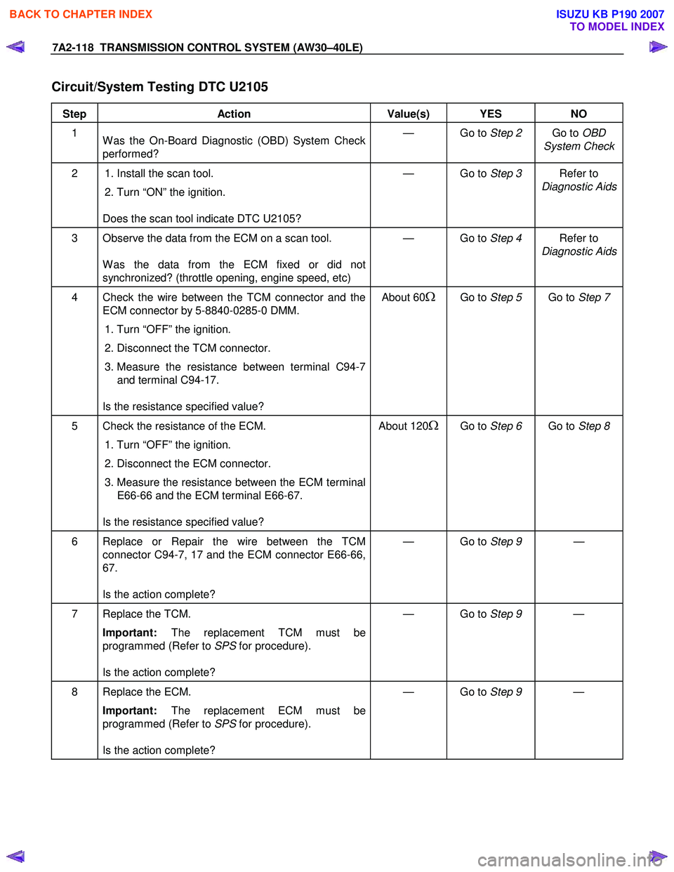
Circuit/System Testing DTC U2105
Step Action Value(s) YES NO
1
W as the On-Board Diagnostic (OBD) System Check
performed? — Go to
Step 2 Go to OBD
System Check
2 1. Install the scan tool.
2. Turn “ON” the ignition.
Does the scan tool indicate DTC U2105? — Go to
Step 3 Refer to
Diagnostic Aids
3 Observe the data from the ECM on a scan tool.
W as the data from the ECM fixed or did not
synchronized? (throttle opening, engine speed, etc) — Go to
Step 4 Refer to
Diagnostic Aids
4 Check the wire between the TCM connector and the ECM connector by 5-8840-0285-0 DMM.
1. Turn “OFF” the ignition.
2. Disconnect the TCM connector.
3. Measure the resistance between terminal C94-7
and terminal C94-17.
Is the resistance specified value? About 60Ω Go to
Step 5 Go to Step 7
5 Check the resistance of the ECM.
1. Turn “OFF” the ignition.
2. Disconnect the ECM connector.
3. Measure the resistance between the ECM terminal
E66-66 and the ECM terminal E66-67.
Is the resistance specified value? About 120ΩGo to
Step 6 Go to Step 8
6 Replace or Repair the wire between the TCM
connector C94-7, 17 and the ECM connector E66-66,
67.
Is the action complete? — Go to
Step 9 —
7 Replace the TCM.
Important: The replacement TCM must be
programmed (Refer to SPS for procedure).
Is the action complete? — Go to
Step 9 —
8 Replace the ECM.
Important: The replacement ECM must be
programmed (Refer to SPS for procedure).
Is the action complete? — Go to
Step 9 —
BACK TO CHAPTER INDEX
TO MODEL INDEX
ISUZU KB P190 2007
Page 4094 of 6020

ON-VEHICLE SERVICE (AW30–40LE) 7A3-9
Manual Shifting Test
NOTE: W ith this test, it can be determined whether the
trouble lies within the electrical circuit or is a mechanical
problem in the transmission.
1. Disconnect TCM connector
2. Inspect manual driving operation
Check that the relation of the position between
select lever and gear corresponds to the following
table.
If any abnormality is found in the above test, do
perform the stall, time lag or gear shift tests.
RTW 77ASH002901
3. Connect TCM connector
W ith the engine off, connect the TCM connector.
Stall Test
RTW 67ALH000101
The object of this test is to check the overall
performance of the transmission and engine b
y
measuring the maximum engine speeds at the “D" and
“R" positions.
NOTE:
1. Perform the test at normal operating fluid
temperature (50 – 80 °C or 122 – 176 °F).
2. Do not continuously run this test longer than 5 seconds.
BACK TO CHAPTER INDEX
TO MODEL INDEX
ISUZU KB P190 2007
Page 4097 of 6020
7A3-12 ON-VEHICLE SERVICE (AW30–40LE)
Measure Line Pressure
1. Fully apply the parking brake and chock the four
wheels.
2. Start the engine and check idling rpm.
3. Select into “D" position, step down strongly on the brake pedal with your left foot and while
manipulating the accelerator pedal with the right
foot, measure the line pressures at the engine
speeds specified in the table.
4. In the same manner, perform the test in “R" position.
Line pressure kPa (kg/cm
2/psi) Engine
speed “D" position “R" position
Idling 349 – 408
(3.6 – 4.2 /51 – 59) 577 – 675
(5.9 – 6.9/84 – 98)
Stall 1,206 – 1,353
(12.3–13.8/175–196) 1,646 – 1,979
(16.8–20.2/239–287)
Evaluation
1. If the measured values at all positions are higher
than specified:
• Pressure control solenoid defective
• Primary regulator valve defective
2. If the measured values at all positions are lowe
r
than specified:
• Primary regulator valve defective
• Oil pump defective
• Pressure control solenoid defective
3. If pressure is low in “D" position only:
• “D" position circuit fluid leakage
4. If pressure is low in “R" position only:
• “R" position circuit fluid leakage
Road Test
NOTE: Perform the test at normal operating fluid
temperature (50 – 80 °C or 122 – 176 °F).
“D" Position Test in “NORMAL", and
“POWER" Pattern
Select into the “D" position and hold the accelerator
pedal constant at the 50% and 100% throttle valve
opening positions.
Push in one of the pattern selector buttons and check
the following:
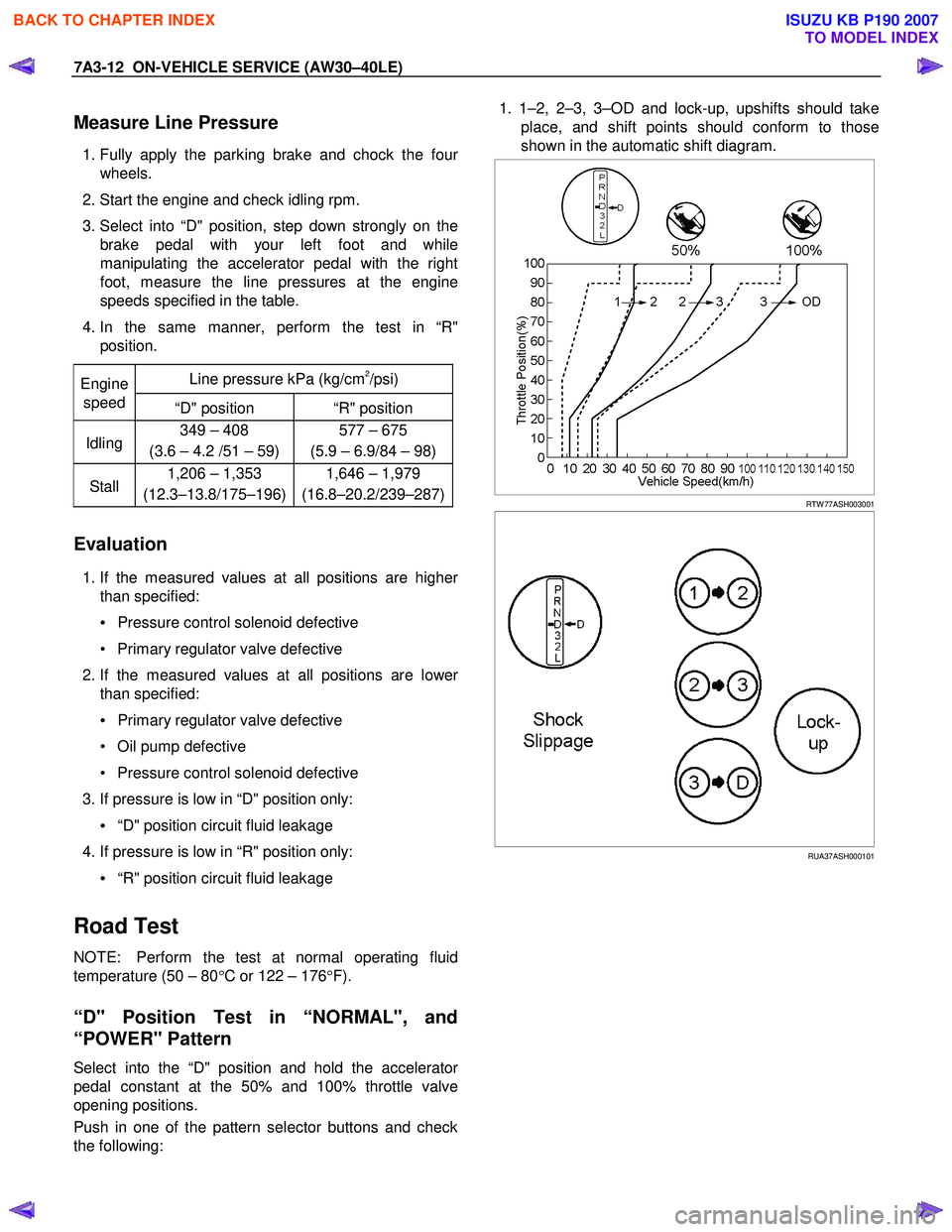
1. 1–2, 2–3, 3–OD and lock-up, upshifts should take
place, and shift points should conform to those
shown in the automatic shift diagram.
RTW 77ASH003001
RUA37ASH000101
BACK TO CHAPTER INDEX
TO MODEL INDEX
ISUZU KB P190 2007
Page 4105 of 6020
7A3-20 ON-VEHICLE SERVICE (AW30–40LE)
Neutral Start Switch (Mode Switch)
Inspection
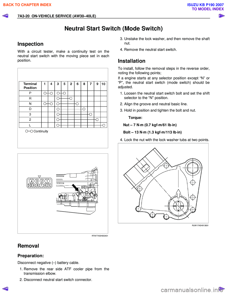
W ith a circuit tester, make a continuity test on the
neutral start switch with the moving piece set in each
position.
RTW 77ASH003401
Removal
Preparation:
Disconnect negative (–) battery cable.
1. Remove the rear side ATF cooler pipe from the
transmission elbow.
2. Disconnect neutral start switch connector.
3. Unstake the lock washer, and then remove the shaft
nut.
4. Remove the neutral start switch.
Installation
To install, follow the removal steps in the reverse order,
noting the following points;
If a engine starts at any selector position except “N” o
r
“P”, the neutral start switch (mode switch) should be
adjusted.
1. Loosen the neutral start switch bolt and set the shift
selector to the “N" position.
2. Align the groove and neutral basic line.
3. Hold in position and tighten the bolt and nut.
Torque:
Nut – 7 N ⋅
⋅⋅
⋅
m (0.7 kgf ⋅
⋅⋅
⋅
m/61 Ib ⋅
⋅⋅
⋅
in)
Bolt – 13 N ⋅
⋅⋅
⋅
m (1.3 kgf ⋅
⋅⋅
⋅
m/113 Ib ⋅
⋅⋅
⋅
in)
4. Lock the nut with the lock washer tubs at two points.
RUW 17ASH013601
BACK TO CHAPTER INDEX
TO MODEL INDEX
ISUZU KB P190 2007
Page 4240 of 6020
CONSTRUCTION AND FUNCTION 7A1-1
SECTION 7A1
CONSTRUCTION AND FUNCTION (JR405E)
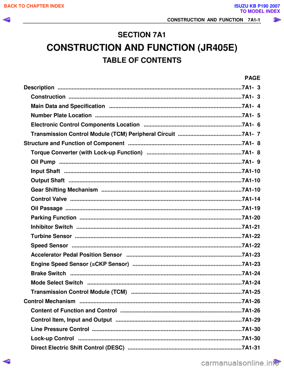
TABLE OF CONTENTS
PAGE
Description ................................................................................................................... ...7A1- 3
Construction ...............................................................................................................7A1 - 3
Main Data and Specification .....................................................................................7A1- 4
Number Plate Location ..............................................................................................7A1- 5
Electronic Control Components Location ...............................................................7A1- 6
Transmission Control Module (TCM) Peripheral Circuit .........................................7A1- 7
Structure and Function of Component .........................................................................7A1- 8
Torque Converter (with Lock-up Function) .............................................................7A1- 8
Oil Pump .....................................................................................................................7 A1- 9
Input Shaft ..................................................................................................................7 A1- 10
Output Shaft ...............................................................................................................7A1 - 10
Gear Shifting Mechanism ..........................................................................................7A1- 10
Control Valve ..............................................................................................................7A1 - 14
Oil Passage .................................................................................................................7A 1- 19
Parking Function ........................................................................................................7A1- 2 0
Inhibitor Switch ..........................................................................................................7A1- 21
Turbine Sensor ...........................................................................................................7A1- 22
Speed Sensor .............................................................................................................7A1- 22
Accelerator Pedal Position Sensor ..........................................................................7A1- 23
Engine Speed Sensor (=CKP Sensor) ......................................................................7A1- 23
Brake Switch ..............................................................................................................7A1- 24
Mode Select Switch ...................................................................................................7A1- 24
Transmission Control Module (TCM) .......................................................................7A1- 25
Control Mechanism ........................................................................................................7A1- 26
Content of Function and Control ..............................................................................7A1- 26
Control Item, Input and Output .................................................................................7A1- 29
Line Pressure Control ................................................................................................7A1- 30
Lock-up Control .........................................................................................................7A1- 3 0
Direct Electric Shift Control (DESC) .........................................................................7A1- 31
BACK TO CHAPTER INDEX
TO MODEL INDEX
ISUZU KB P190 2007
Page 4241 of 6020
7A1-2 CONSTRUCTION AND FUNCTION
PAGE
Learning Function ......................................................................................................7A1- 33
Major Input/Output Component and Their Functions .............................................7A1- 34
Control Circuit Block Diagram ..................................................................................7A1- 35
Gear Train (Transmission Mechanism) Operation and Hydraulic Circuit ..................7A1- 36
Construction and Operation .....................................................................................7A1- 36
Component Name and Function ...............................................................................7A1- 36
Component and Their Operating Condition ............................................................7A1- 37
BACK TO CHAPTER INDEX
TO MODEL INDEX
ISUZU KB P190 2007
Page 4246 of 6020
CONSTRUCTION AND FUNCTION 7A1-7
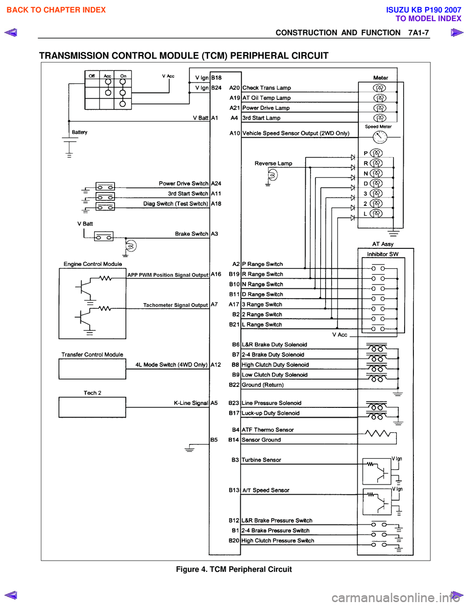
TRANSMISSION CONTROL MODULE (TCM) PERIPHERAL CIRCUIT
Figure 4. TCM Peripheral Circuit
BACK TO CHAPTER INDEX
TO MODEL INDEX
ISUZU KB P190 2007
Page 4247 of 6020
7A1-8 CONSTRUCTION AND FUNCTION
STRUCTURE AND FUNCTION OF COMPONENT
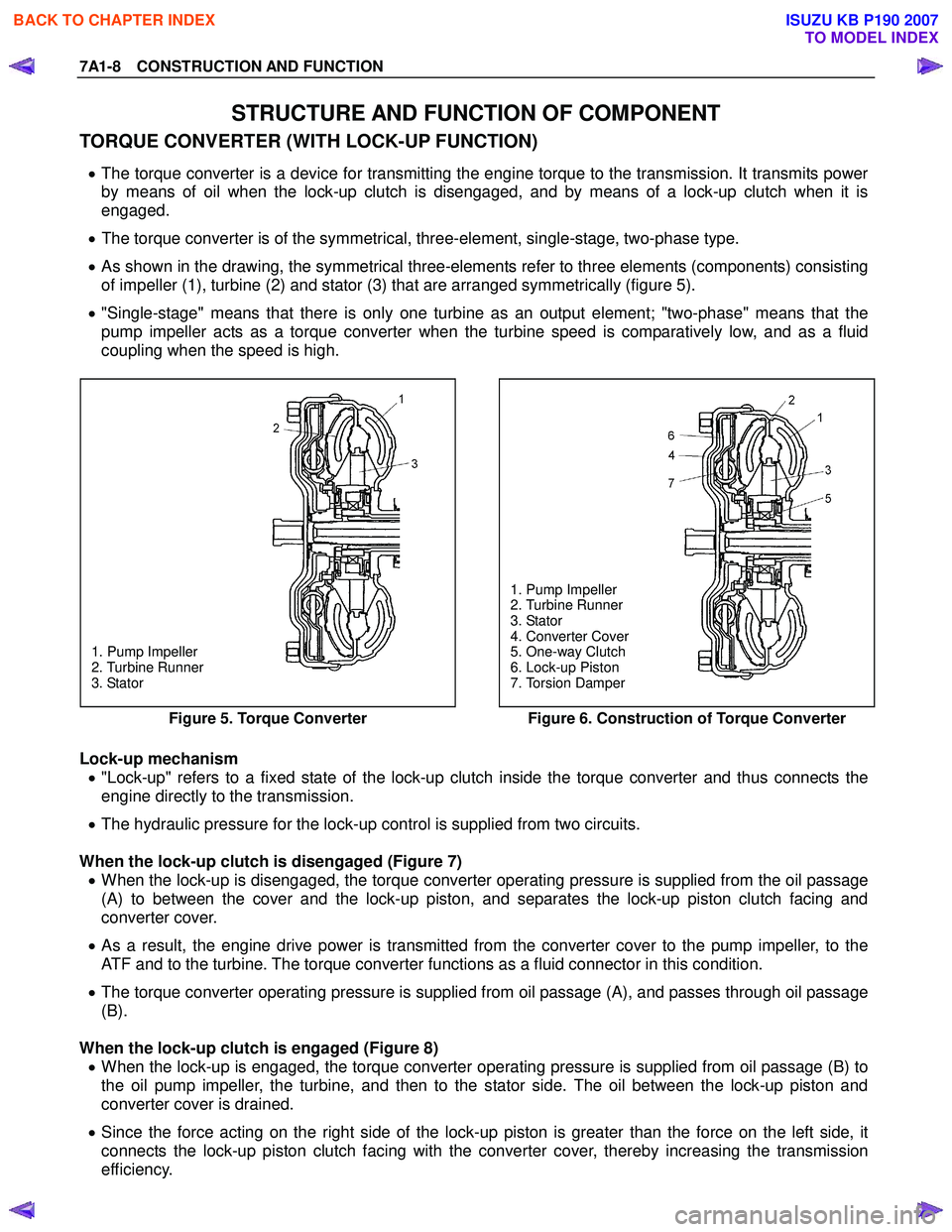
TORQUE CONVERTER (WITH LOCK-UP FUNCTION)
• The torque converter is a device for transmitting the engine torque to the transmission. It transmits power
by means of oil when the lock-up clutch is disengaged, and by means of a lock-up clutch when it is
engaged.
• The torque converter is of the symmetrical, three-element, single-stage, two-phase type.
• As shown in the drawing, the symmetrical three-elements refer to three elements (components) consisting
of impeller (1), turbine (2) and stator (3) that are arranged symmetrically (figure 5).
• "Single-stage" means that there is only one turbine as an output element; "two-phase" means that the
pump impeller acts as a torque converter when the turbine speed is comparatively low, and as a fluid
coupling when the speed is high.
1. Pump Impeller
2. Turbine Runner
3. Stator
1. Pump Impeller
2. Turbine Runner
3. Stator
4. Converter Cover
5. One-way Clutch
6. Lock-up Piston
7. Torsion Damper
Figure 5. Torque Converter
Figure 6. Construction of Torque Converter
Lock-up mechanism
• "Lock-up" refers to a fixed state of the lock-up clutch inside the torque converter and thus connects the
engine directly to the transmission.
• The hydraulic pressure for the lock-up control is supplied from two circuits.
When the lock-up clutch is disengaged (Figure 7) • When the lock-up is disengaged, the torque converter operating pressure is supplied from the oil pass age
(A) to between the cover and the lock-up piston, and separates the lock-up piston clutch facing and
converter cover.
• As a result, the engine drive power is transmitted from the converter cover to the pump impeller, to the
ATF and to the turbine. The torque converter functions as a fluid connector in this condition.
• The torque converter operating pressure is supplied from oil passage (A), and passes through oil passage
(B).
When the lock-up clutch is engaged (Figure 8) • When the lock-up is engaged, the torque converter operating pressure is supplied from oil passage (B) to
the oil pump impeller, the turbine, and then to the stator side. The oil between the lock-up piston and
converter cover is drained.
• Since the force acting on the right side of the lock-up piston is greater than the force on the left side, it
connects the lock-up piston clutch facing with the converter cover, thereby increasing the transmission
efficiency.
BACK TO CHAPTER INDEX
TO MODEL INDEX
ISUZU KB P190 2007