2007 ISUZU KB P190 turn signal
[x] Cancel search: turn signalPage 1669 of 6020
6E-52 ENGINE CONTROL SYSTEM (4JK1/4JJ1)
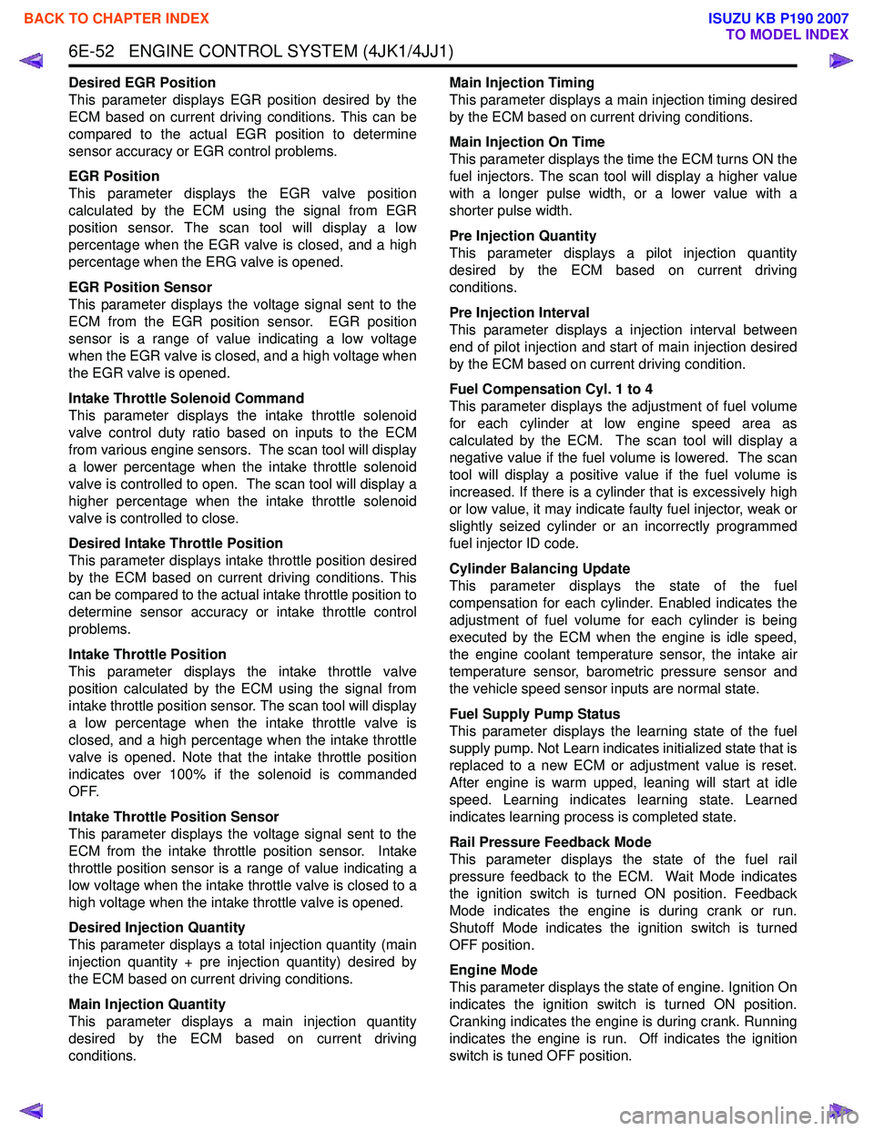
Desired EGR Position
This parameter displays EGR position desired by the
ECM based on current driving conditions. This can be
compared to the actual EGR position to determine
sensor accuracy or EGR control problems.
EGR Position
This parameter displays the EGR valve position
calculated by the ECM using the signal from EGR
position sensor. The scan tool will display a low
percentage when the EGR valve is closed, and a high
percentage when the ERG valve is opened.
EGR Position Sensor
This parameter displays the voltage signal sent to the
ECM from the EGR position sensor. EGR position
sensor is a range of value indicating a low voltage
when the EGR valve is closed, and a high voltage when
the EGR valve is opened.
Intake Throttle Solenoid Command
This parameter displays the intake throttle solenoid
valve control duty ratio based on inputs to the ECM
from various engine sensors. The scan tool will display
a lower percentage when the intake throttle solenoid
valve is controlled to open. The scan tool will display a
higher percentage when the intake throttle solenoid
valve is controlled to close.
Desired Intake Throttle Position
This parameter displays intake throttle position desired
by the ECM based on current driving conditions. This
can be compared to the actual intake throttle position to
determine sensor accuracy or intake throttle control
problems.
Intake Throttle Position
This parameter displays the intake throttle valve
position calculated by the ECM using the signal from
intake throttle position sensor. The scan tool will display
a low percentage when the intake throttle valve is
closed, and a high percentage when the intake throttle
valve is opened. Note that the intake throttle position
indicates over 100% if the solenoid is commanded
OFF.
Intake Throttle Position Sensor
This parameter displays the voltage signal sent to the
ECM from the intake throttle position sensor. Intake
throttle position sensor is a range of value indicating a
low voltage when the intake throttle valve is closed to a
high voltage when the intake throttle valve is opened.
Desired Injection Quantity
This parameter displays a total injection quantity (main
injection quantity + pre injection quantity) desired by
the ECM based on current driving conditions.
Main Injection Quantity
This parameter displays a main injection quantity
desired by the ECM based on current driving
conditions. Main Injection Timing
This parameter displays a main injection timing desired
by the ECM based on current driving conditions.
Main Injection On Time
This parameter displays the time the ECM turns ON the
fuel injectors. The scan tool will display a higher value
with a longer pulse width, or a lower value with a
shorter pulse width.
Pre Injection Quantity
This parameter displays a pilot injection quantity
desired by the ECM based on current driving
conditions.
Pre Injection Interval
This parameter displays a injection interval between
end of pilot injection and start of main injection desired
by the ECM based on current driving condition.
Fuel Compensation Cyl. 1 to 4
This parameter displays the adjustment of fuel volume
for each cylinder at low engine speed area as
calculated by the ECM. The scan tool will display a
negative value if the fuel volume is lowered. The scan
tool will display a positive value if the fuel volume is
increased. If there is a cylinder that is excessively high
or low value, it may indicate faulty fuel injector, weak or
slightly seized cylinder or an incorrectly programmed
fuel injector ID code.
Cylinder Balancing Update
This parameter displays the state of the fuel
compensation for each cylinder. Enabled indicates the
adjustment of fuel volume for each cylinder is being
executed by the ECM when the engine is idle speed,
the engine coolant temperature sensor, the intake air
temperature sensor, barometric pressure sensor and
the vehicle speed sensor inputs are normal state.
Fuel Supply Pump Status
This parameter displays the learning state of the fuel
supply pump. Not Learn indicates initialized state that is
replaced to a new ECM or adjustment value is reset.
After engine is warm upped, leaning will start at idle
speed. Learning indicates learning state. Learned
indicates learning process is completed state.
Rail Pressure Feedback Mode
This parameter displays the state of the fuel rail
pressure feedback to the ECM. Wait Mode indicates
the ignition switch is turned ON position. Feedback
Mode indicates the engine is during crank or run.
Shutoff Mode indicates the ignition switch is turned
OFF position.
Engine Mode
This parameter displays the state of engine. Ignition On
indicates the ignition switch is turned ON position.
Cranking indicates the engine is during crank. Running
indicates the engine is run. Off indicates the ignition
switch is tuned OFF position.
BACK TO CHAPTER INDEX
TO MODEL INDEX
ISUZU KB P190 2007
Page 1670 of 6020
ENGINE CONTROL SYSTEM (4JK1/4JJ1) 6E-53
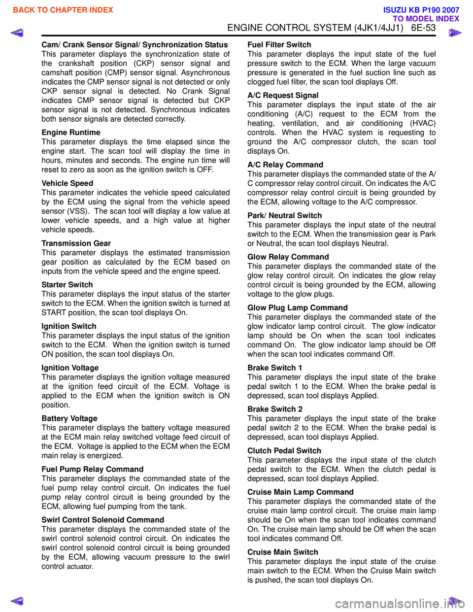
Cam/ Crank Sensor Signal/ Synchronization Status
This parameter displays the synchronization state of
the crankshaft position (CKP) sensor signal and
camshaft position (CMP) sensor signal. Asynchronous
indicates the CMP sensor signal is not detected or only
CKP sensor signal is detected. No Crank Signal
indicates CMP sensor signal is detected but CKP
sensor signal is not detected. Synchronous indicates
both sensor signals are detected correctly.
Engine Runtime
This parameter displays the time elapsed since the
engine start. The scan tool will display the time in
hours, minutes and seconds. The engine run time will
reset to zero as soon as the ignition switch is OFF.
Vehicle Speed
This parameter indicates the vehicle speed calculated
by the ECM using the signal from the vehicle speed
sensor (VSS). The scan tool will display a low value at
lower vehicle speeds, and a high value at higher
vehicle speeds.
Transmission Gear
This parameter displays the estimated transmission
gear position as calculated by the ECM based on
inputs from the vehicle speed and the engine speed.
Starter Switch
This parameter displays the input status of the starter
switch to the ECM. When the ignition switch is turned at
START position, the scan tool displays On.
Ignition Switch
This parameter displays the input status of the ignition
switch to the ECM. When the ignition switch is turned
ON position, the scan tool displays On.
Ignition Voltage
This parameter displays the ignition voltage measured
at the ignition feed circuit of the ECM. Voltage is
applied to the ECM when the ignition switch is ON
position.
Battery Voltage
This parameter displays the battery voltage measured
at the ECM main relay switched voltage feed circuit of
the ECM. Voltage is applied to the ECM when the ECM
main relay is energized.
Fuel Pump Relay Command
This parameter displays the commanded state of the
fuel pump relay control circuit. On indicates the fuel
pump relay control circuit is being grounded by the
ECM, allowing fuel pumping from the tank.
Swirl Control Solenoid Command
This parameter displays the commanded state of the
swirl control solenoid control circuit. On indicates the
swirl control solenoid control circuit is being grounded
by the ECM, allowing vacuum pressure to the swirl
control
actuator. Fuel Filter Switch
This parameter displays the input state of the fuel
pressure switch to the ECM. When the large vacuum
pressure is generated in the fuel suction line such as
clogged fuel filter, the scan tool displays Off.
A/C Request Signal
This parameter displays the input state of the air
conditioning (A/C) request to the ECM from the
heating, ventilation, and air conditioning (HVAC)
controls. When the HVAC system is requesting to
ground the A/C compressor clutch, the scan tool
displays On.
A/C Relay Command
This parameter displays the commanded state of the A/
C compressor relay control circuit. On indicates the A/C
compressor relay control circuit is being grounded by
the ECM, allowing voltage to the A/C compressor.
Park/ Neutral Switch
This parameter displays the input state of the neutral
switch to the ECM. When the transmission gear is Park
or Neutral, the scan tool displays Neutral.
Glow Relay Command
This parameter displays the commanded state of the
glow relay control circuit. On indicates the glow relay
control circuit is being grounded by the ECM, allowing
voltage to the glow plugs.
Glow Plug Lamp Command
This parameter displays the commanded state of the
glow indicator lamp control circuit. The glow indicator
lamp should be On when the scan tool indicates
command On. The glow indicator lamp should be Off
when the scan tool indicates command Off.
Brake Switch 1
This parameter displays the input state of the brake
pedal switch 1 to the ECM. When the brake pedal is
depressed, scan tool displays Applied.
Brake Switch 2
This parameter displays the input state of the brake
pedal switch 2 to the ECM. When the brake pedal is
depressed, scan tool displays Applied.
Clutch Pedal Switch
This parameter displays the input state of the clutch
pedal switch to the ECM. When the clutch pedal is
depressed, scan tool displays Applied.
Cruise Main Lamp Command
This parameter displays the commanded state of the
cruise main lamp control circuit. The cruise main lamp
should be On when the scan tool indicates command
On. The cruise main lamp should be Off when the scan
tool indicates command Off.
Cruise Main Switch
This parameter displays the input state of the cruise
main switch to the ECM. When the Cruise Main switch
is pushed, the scan tool displays On.
BACK TO CHAPTER INDEX
TO MODEL INDEX
ISUZU KB P190 2007
Page 1671 of 6020
6E-54 ENGINE CONTROL SYSTEM (4JK1/4JJ1)
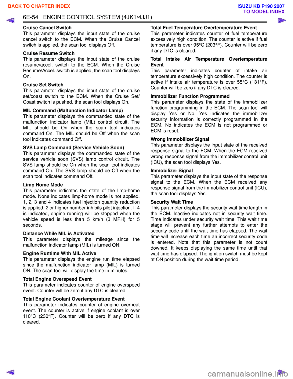
Cruise Cancel Switch
This parameter displays the input state of the cruise
cancel switch to the ECM. When the Cruise Cancel
switch is applied, the scan tool displays Off.
Cruise Resume Switch
This parameter displays the input state of the cruise
resume/accel. switch to the ECM. When the Cruise
Resume/Accel. switch is applied, the scan tool displays
On.
Cruise Set Switch
This parameter displays the input state of the cruise
set/coast switch to the ECM. When the Cruise Set/
Coast switch is pushed, the scan tool displays On.
MIL Command (Malfunction Indicator Lamp)
This parameter displays the commanded state of the
malfunction indicator lamp (MIL) control circuit. The
MIL should be On when the scan tool indicates
command On. The MIL should be Off when the scan
tool indicates command Off.
SVS Lamp Command (Service Vehicle Soon)
This parameter displays the commanded state of the
service vehicle soon (SVS) lamp control circuit. The
SVS lamp should be On when the scan tool indicates
command On. The SVS lamp should be Off when the
scan tool indicates command Off.
Limp Home Mode
This parameter indicates the state of the limp-home
mode. None indicates limp-home mode is not applied.
1, 2, 3 and 4 indicates fuel injection quantity reduction
is applied. 2 or higher number inhibits pilot injection. If 4
is indicated, engine running will be stopped when the
vehicle speed is less than 5 km/h (3 MPH) for 5
seconds.
Distance While MIL is Activated
This parameter displays the mileage since the
malfunction indicator lamp (MIL) is turned ON.
Engine Runtime With MIL Active
This parameter displays the engine run time elapsed
since the malfunction indicator lamp (MIL) is turned
ON. The scan tool will display the time in minutes.
Total Engine Overspeed Event
This parameter indicates counter of engine overspeed
event. Counter will be zero if any DTC is cleared.
Total Engine Coolant Overtemperature Event
This parameter indicates counter of engine overheat
event. The counter is active if engine coolant is over
11 0 °C (230 °F). Counter will be zero if any DTC is
cleared. Total Fuel Temperature Overtemperature Event
This parameter indicates counter of fuel temperature
excessively high condition. The counter is active if fuel
temperature is over 95 °C (203 °F). Counter will be zero
if any DTC is cleared.
Total Intake Air Temperature Overtemperature
Event
This parameter indicates counter of intake air
temperature excessively high condition. The counter is
active if intake air temperature is over 55 °C (131 °F).
Counter will be zero if any DTC is cleared.
Immobilizer Function Programmed
This parameter displays the state of the immobilizer
function programming in the ECM. The scan tool will
display Yes or No. Yes indicates the immobilizer
security information is correctly programmed in the
ECM. No indicates the ECM is not programmed or
ECM is reset.
Wrong Immobilizer Signal
This parameter displays the input state of the received
response signal to the ECM. When the ECM received
wrong response signal from the immobilizer control unit
(ICU), the scan tool displays Yes.
Immobilizer Signal
This parameter displays the input state of the response
signal to the ECM. When the ECM received any
response signal from the immobilizer control unit (ICU),
the scan tool displays Yes.
Security Wait Time
This parameter displays the security wait time length in
the ECM. Inactive indicates not in security wait time.
Time indicates under security wait time. This wait time
stage will prevent any further attempts to enter the
security code until the wait time has elapsed. The wait
time will increase each time an incorrect security code
is entered. Note that this parameter is not count
downed. It keeps displaying the same time until that
wait time has elapsed. The ignition switch must be kept
at ON position during the wait time period.
BACK TO CHAPTER INDEX
TO MODEL INDEX
ISUZU KB P190 2007
Page 1673 of 6020
6E-56 ENGINE CONTROL SYSTEM (4JK1/4JJ1)
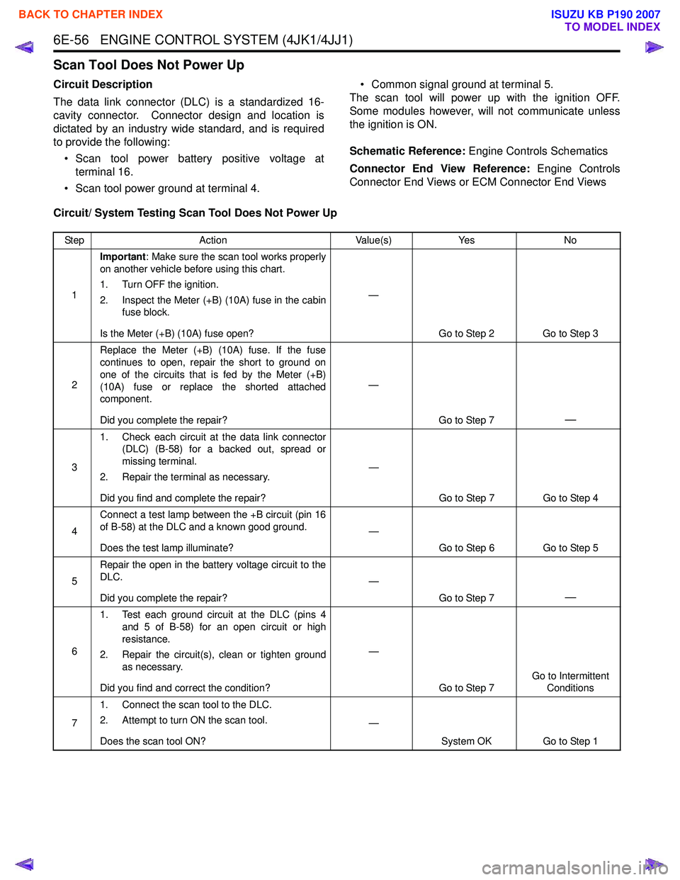
Scan Tool Does Not Power Up
Circuit Description
The data link connector (DLC) is a standardized 16-
cavity connector. Connector design and location is
dictated by an industry wide standard, and is required
to provide the following:
• Scan tool power battery positive voltage at terminal 16.
• Scan tool power ground at terminal 4. • Common signal ground at terminal 5.
The scan tool will power up with the ignition OFF.
Some modules however, will not communicate unless
the ignition is ON.
Schematic Reference: Engine Controls Schematics
Connector End View Reference: Engine Controls
Connector End Views or ECM Connector End Views
Circuit/ System Testing Scan Tool Does Not Power Up
Step Action Value(s)Yes No
1 Important
: Make sure the scan tool works properly
on another vehicle before using this chart.
1. Turn OFF the ignition.
2. Inspect the Meter (+B) (10A) fuse in the cabin fuse block.
Is the Meter (+B) (10A) fuse open? —
Go to Step 2 Go to Step 3
2 Replace the Meter (+B) (10A) fuse. If the fuse
continues to open, repair the short to ground on
one of the circuits that is fed by the Meter (+B)
(10A) fuse or replace the shorted attached
component.
Did you complete the repair? —
Go to Step 7
—
31. Check each circuit at the data link connector
(DLC) (B-58) for a backed out, spread or
missing terminal.
2. Repair the terminal as necessary.
Did you find and complete the repair? —
Go to Step 7 Go to Step 4
4 Connect a test lamp between the +B circuit (pin 16
of B-58) at the DLC and a known good ground.
Does the test lamp illuminate? —
Go to Step 6 Go to Step 5
5 Repair the open in the battery voltage circuit to the
DLC.
Did you complete the repair? —
Go to Step 7
—
61. Test each ground circuit at the DLC (pins 4
and 5 of B-58) for an open circuit or high
resistance.
2. Repair the circuit(s), clean or tighten ground as necessary.
Did you find and correct the condition? —
Go to Step 7 Go to Intermittent
Conditions
7 1. Connect the scan tool to the DLC.
2. Attempt to turn ON the scan tool.
Does the scan tool ON? —
System OK Go to Step 1
BACK TO CHAPTER INDEX
TO MODEL INDEX
ISUZU KB P190 2007
Page 1686 of 6020
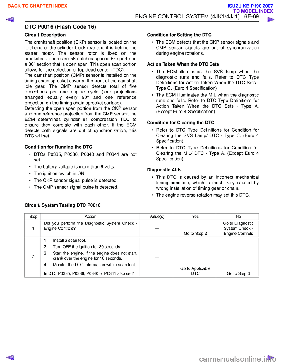
ENGINE CONTROL SYSTEM (4JK1/4JJ1) 6E-69
DTC P0016 (Flash Code 16)
Circuit Description
The crankshaft position (CKP) sensor is located on the
left-hand of the cylinder block rear and it is behind the
starter motor. The sensor rotor is fixed on the
crankshaft. There are 56 notches spaced 6 ° apart and
a 30 ° section that is open span. This open span portion
allows for the detection of top dead center (TDC).
The camshaft position (CMP) sensor is installed on the
timing chain sprocket cover at the front of the camshaft
idle gear. The CMP sensor detects total of five
projections per one engine cycle (four projections
arranged equally every 90 ° and one reference
projection on the timing chain sprocket surface).
Detecting the open span portion from the CKP sensor
and one reference projection from the CMP sensor, the
ECM determines cylinder #1 compression TDC to
ensure they correlate with each other. If the ECM
detects both signals are out of synchronization, this
DTC will set.
Condition for Running the DTC • DTCs P0335, P0336, P0340 and P0341 are not set.
• The battery voltage is more than 9 volts.
• The ignition switch is ON.
• The CKP sensor signal pulse is detected.
• The CMP sensor signal pulse is detected. Condition for Setting the DTC
• The ECM detects that the CKP sensor signals and CMP sensor signals are out of synchronization
during engine rotations.
Action Taken When the DTC Sets • The ECM illuminates the SVS lamp when the diagnostic runs and fails. Refer to DTC Type
Definitions for Action Taken When the DTC Sets -
Type C. (Euro 4 Specification)
• The ECM illuminates the MIL when the diagnostic runs and fails. Refer to DTC Type Definitions for
Action Taken When the DTC Sets - Type A.
(Except Euro 4 Specification)
Condition for Clearing the DTC • Refer to DTC Type Definitions for Condition for Clearing the SVS Lamp/ DTC - Type C. (Euro 4
Specification)
• Refer to DTC Type Definitions for Condition for Clearing the MIL/ DTC - Type A. (Except Euro 4
Specification)
Diagnostic Aids • This DTC is caused by an incorrect mechanical timing condition, which is most likely caused by
wrong installation of timing gear or chain.
• The engine reverse rotation may set this DTC.
Circuit/ System Testing DTC P0016
Step Action Value(s)Yes No
1 Did you perform the Diagnostic System Check -
Engine Controls? —
Go to Step 2 Go to Diagnostic
System Check -
Engine Controls
2 1. Install a scan tool.
2. Turn OFF the ignition for 30 seconds.
3. Start the engine. If the engine does not start, crank over the engine for 10 seconds.
4. Monitor the DTC Information with a scan tool.
Is DTC P0335, P0336, P0340 or P0341 also set? —
Go to Applicable DTC Go to Step 3
BACK TO CHAPTER INDEX
TO MODEL INDEX
ISUZU KB P190 2007
Page 1712 of 6020
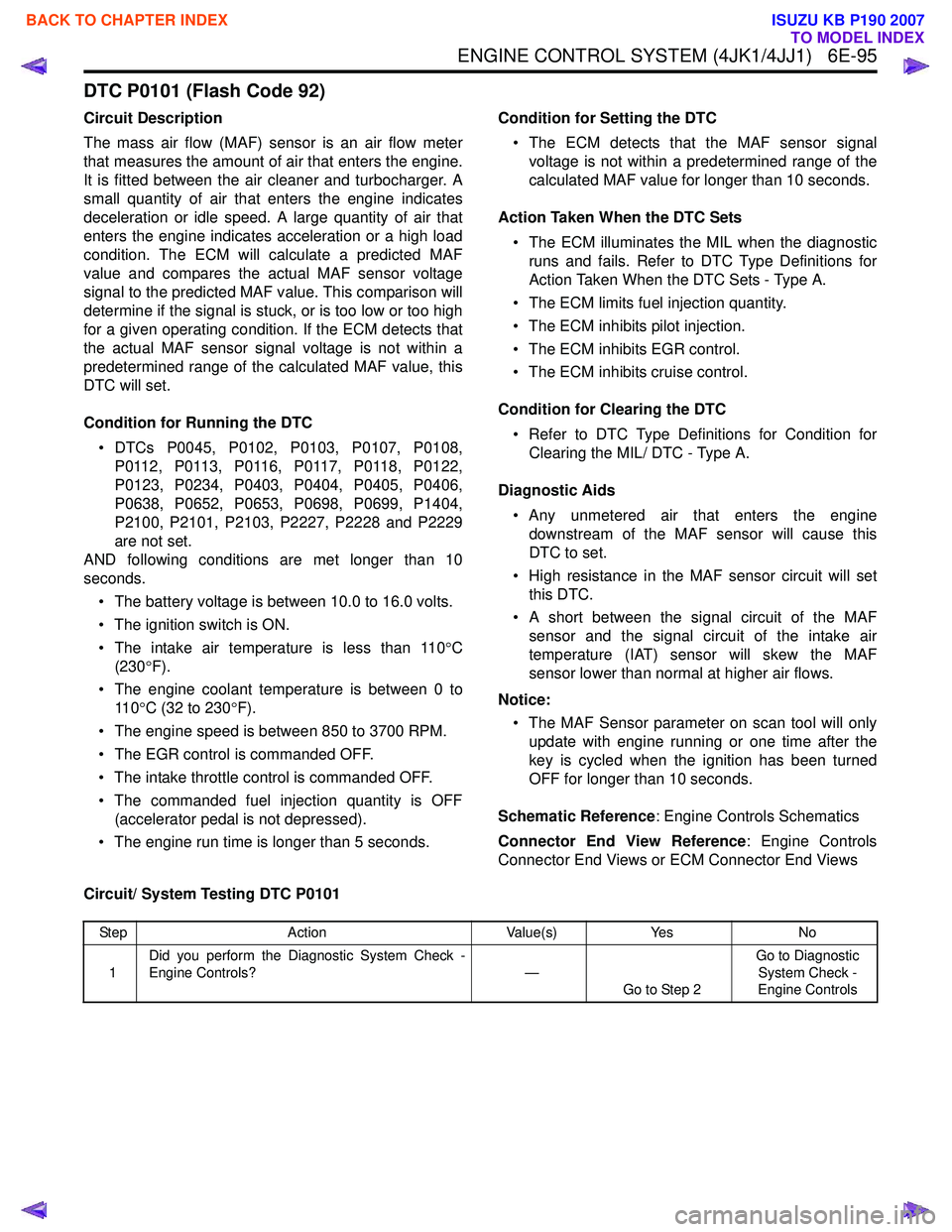
ENGINE CONTROL SYSTEM (4JK1/4JJ1) 6E-95
DTC P0101 (Flash Code 92)
Circuit Description
The mass air flow (MAF) sensor is an air flow meter
that measures the amount of air that enters the engine.
It is fitted between the air cleaner and turbocharger. A
small quantity of air that enters the engine indicates
deceleration or idle speed. A large quantity of air that
enters the engine indicates acceleration or a high load
condition. The ECM will calculate a predicted MAF
value and compares the actual MAF sensor voltage
signal to the predicted MAF value. This comparison will
determine if the signal is stuck, or is too low or too high
for a given operating condition. If the ECM detects that
the actual MAF sensor signal voltage is not within a
predetermined range of the calculated MAF value, this
DTC will set.
Condition for Running the DTC • DTCs P0045, P0102, P0103, P0107, P0108, P 0 11 2 , P 0 11 3 , P 0 11 6 , P 0 11 7 , P 0 11 8 , P 0 1 2 2 ,
P0123, P0234, P0403, P0404, P0405, P0406,
P0638, P0652, P0653, P0698, P0699, P1404,
P2100, P2101, P2103, P2227, P2228 and P2229
are not set.
AND following conditions are met longer than 10
seconds.
• The battery voltage is between 10.0 to 16.0 volts.
• The ignition switch is ON.
• The intake air temperature is less than 110 °C
(230 °F).
• The engine coolant temperature is between 0 to 11 0 °C (32 to 230 °F).
• The engine speed is between 850 to 3700 RPM.
• The EGR control is commanded OFF.
• The intake throttle control is commanded OFF.
• The commanded fuel injection quantity is OFF (accelerator pedal is not depressed).
• The engine run time is longer than 5 seconds. Condition for Setting the DTC
• The ECM detects that the MAF sensor signal voltage is not within a predetermined range of the
calculated MAF value for longer than 10 seconds.
Action Taken When the DTC Sets • The ECM illuminates the MIL when the diagnostic runs and fails. Refer to DTC Type Definitions for
Action Taken When the DTC Sets - Type A.
• The ECM limits fuel injection quantity.
• The ECM inhibits pilot injection.
• The ECM inhibits EGR control.
• The ECM inhibits cruise control.
Condition for Clearing the DTC • Refer to DTC Type Definitions for Condition for Clearing the MIL/ DTC - Type A.
Diagnostic Aids • Any unmetered air that enters the engine downstream of the MAF sensor will cause this
DTC to set.
• High resistance in the MAF sensor circuit will set this DTC.
• A short between the signal circuit of the MAF sensor and the signal circuit of the intake air
temperature (IAT) sensor will skew the MAF
sensor lower than normal at higher air flows.
Notice: • The MAF Sensor parameter on scan tool will only update with engine running or one time after the
key is cycled when the ignition has been turned
OFF for longer than 10 seconds.
Schematic Reference : Engine Controls Schematics
Connector End View Reference : Engine Controls
Connector End Views or ECM Connector End Views
Circuit/ System Testing DTC P0101
Step Action Value(s)Yes No
1 Did you perform the Diagnostic System Check -
Engine Controls? —
Go to Step 2 Go to Diagnostic
System Check -
Engine Controls
BACK TO CHAPTER INDEX
TO MODEL INDEX
ISUZU KB P190 2007
Page 1715 of 6020
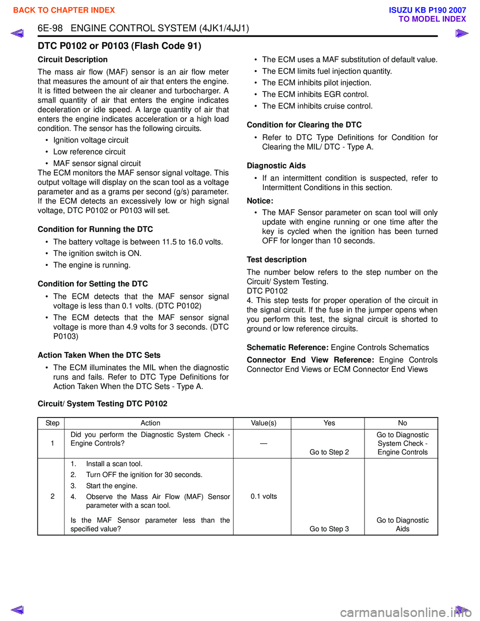
6E-98 ENGINE CONTROL SYSTEM (4JK1/4JJ1)
DTC P0102 or P0103 (Flash Code 91)
Circuit Description
The mass air flow (MAF) sensor is an air flow meter
that measures the amount of air that enters the engine.
It is fitted between the air cleaner and turbocharger. A
small quantity of air that enters the engine indicates
deceleration or idle speed. A large quantity of air that
enters the engine indicates acceleration or a high load
condition. The sensor has the following circuits.
• Ignition voltage circuit
• Low reference circuit
• MAF sensor signal circuit
The ECM monitors the MAF sensor signal voltage. This
output voltage will display on the scan tool as a voltage
parameter and as a grams per second (g/s) parameter.
If the ECM detects an excessively low or high signal
voltage, DTC P0102 or P0103 will set.
Condition for Running the DTC • The battery voltage is between 11.5 to 16.0 volts.
• The ignition switch is ON.
• The engine is running.
Condition for Setting the DTC • The ECM detects that the MAF sensor signal voltage is less than 0.1 volts. (DTC P0102)
• The ECM detects that the MAF sensor signal voltage is more than 4.9 volts for 3 seconds. (DTC
P0103)
Action Taken When the DTC Sets • The ECM illuminates the MIL when the diagnostic runs and fails. Refer to DTC Type Definitions for
Action Taken When the DTC Sets - Type A. • The ECM uses a MAF substitution of default value.
• The ECM limits fuel injection quantity.
• The ECM inhibits pilot injection.
• The ECM inhibits EGR control.
• The ECM inhibits cruise control.
Condition for Clearing the DTC • Refer to DTC Type Definitions for Condition for Clearing the MIL/ DTC - Type A.
Diagnostic Aids • If an intermittent condition is suspected, refer to Intermittent Conditions in this section.
Notice: • The MAF Sensor parameter on scan tool will only update with engine running or one time after the
key is cycled when the ignition has been turned
OFF for longer than 10 seconds.
Test description
The number below refers to the step number on the
Circuit/ System Testing.
DTC P0102
4. This step tests for proper operation of the circuit in
the signal circuit. If the fuse in the jumper opens when
you perform this test, the signal circuit is shorted to
ground or low reference circuits.
Schematic Reference: Engine Controls Schematics
Connector End View Reference: Engine Controls
Connector End Views or ECM Connector End Views
Circuit/ System Testing DTC P0102
Step Action Value(s)Yes No
1 Did you perform the Diagnostic System Check -
Engine Controls? —
Go to Step 2 Go to Diagnostic
System Check -
Engine Controls
2 1. Install a scan tool.
2. Turn OFF the ignition for 30 seconds.
3. Start the engine.
4. Observe the Mass Air Flow (MAF) Sensor parameter with a scan tool.
Is the MAF Sensor parameter less than the
specified value? 0.1 volts
Go to Step 3 Go to Diagnostic
Aids
BACK TO CHAPTER INDEX
TO MODEL INDEX
ISUZU KB P190 2007
Page 1716 of 6020
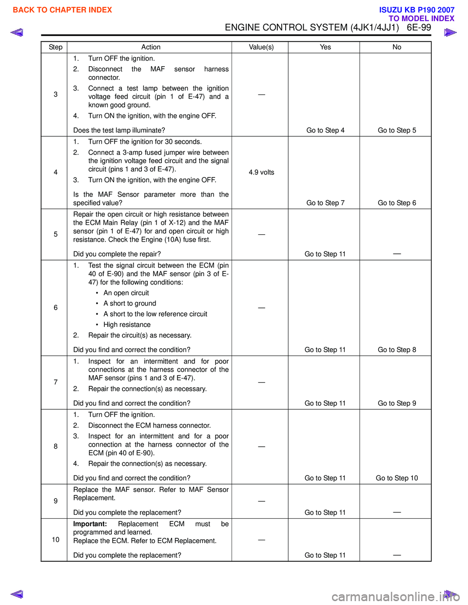
ENGINE CONTROL SYSTEM (4JK1/4JJ1) 6E-99
31. Turn OFF the ignition.
2. Disconnect the MAF sensor harness connector.
3. Connect a test lamp between the ignition voltage feed circuit (pin 1 of E-47) and a
known good ground.
4. Turn ON the ignition, with the engine OFF.
Does the test lamp illuminate? —
Go to Step 4 Go to Step 5
4 1. Turn OFF the ignition for 30 seconds.
2. Connect a 3-amp fused jumper wire between the ignition voltage feed circuit and the signal
circuit (pins 1 and 3 of E-47).
3. Turn ON the ignition, with the engine OFF.
Is the MAF Sensor parameter more than the
specified value? 4.9 volts
Go to Step 7 Go to Step 6
5 Repair the open circuit or high resistance between
the ECM Main Relay (pin 1 of X-12) and the MAF
sensor (pin 1 of E-47) for and open circuit or high
resistance. Check the Engine (10A) fuse first.
Did you complete the repair? —
Go to Step 11
—
61. Test the signal circuit between the ECM (pin
40 of E-90) and the MAF sensor (pin 3 of E-
47) for the following conditions:
• An open circuit
• A short to ground
• A short to the low reference circuit
• High resistance
2. Repair the circuit(s) as necessary.
Did you find and correct the condition? —
Go to Step 11 Go to Step 8
7 1. Inspect for an intermittent and for poor
connections at the harness connector of the
MAF sensor (pins 1 and 3 of E-47).
2. Repair the connection(s) as necessary.
Did you find and correct the condition? —
Go to Step 11 Go to Step 9
8 1. Turn OFF the ignition.
2. Disconnect the ECM harness connector.
3. Inspect for an intermittent and for a poor connection at the harness connector of the
ECM (pin 40 of E-90).
4. Repair the connection(s) as necessary.
Did you find and correct the condition? —
Go to Step 11 Go to Step 10
9 Replace the MAF sensor. Refer to MAF Sensor
Replacement.
Did you complete the replacement? —
Go to Step 11
—
10Important:
Replacement ECM must be
programmed and learned.
Replace the ECM. Refer to ECM Replacement.
Did you complete the replacement? —
Go to Step 11
—
Step Action Value(s)Yes No
BACK TO CHAPTER INDEX
TO MODEL INDEX
ISUZU KB P190 2007