Page 1391 of 6020
ENGINE MECHANICAL (4JK1/4JJ1) 6A-31
Installation
1. Install the intake manifold gasket.
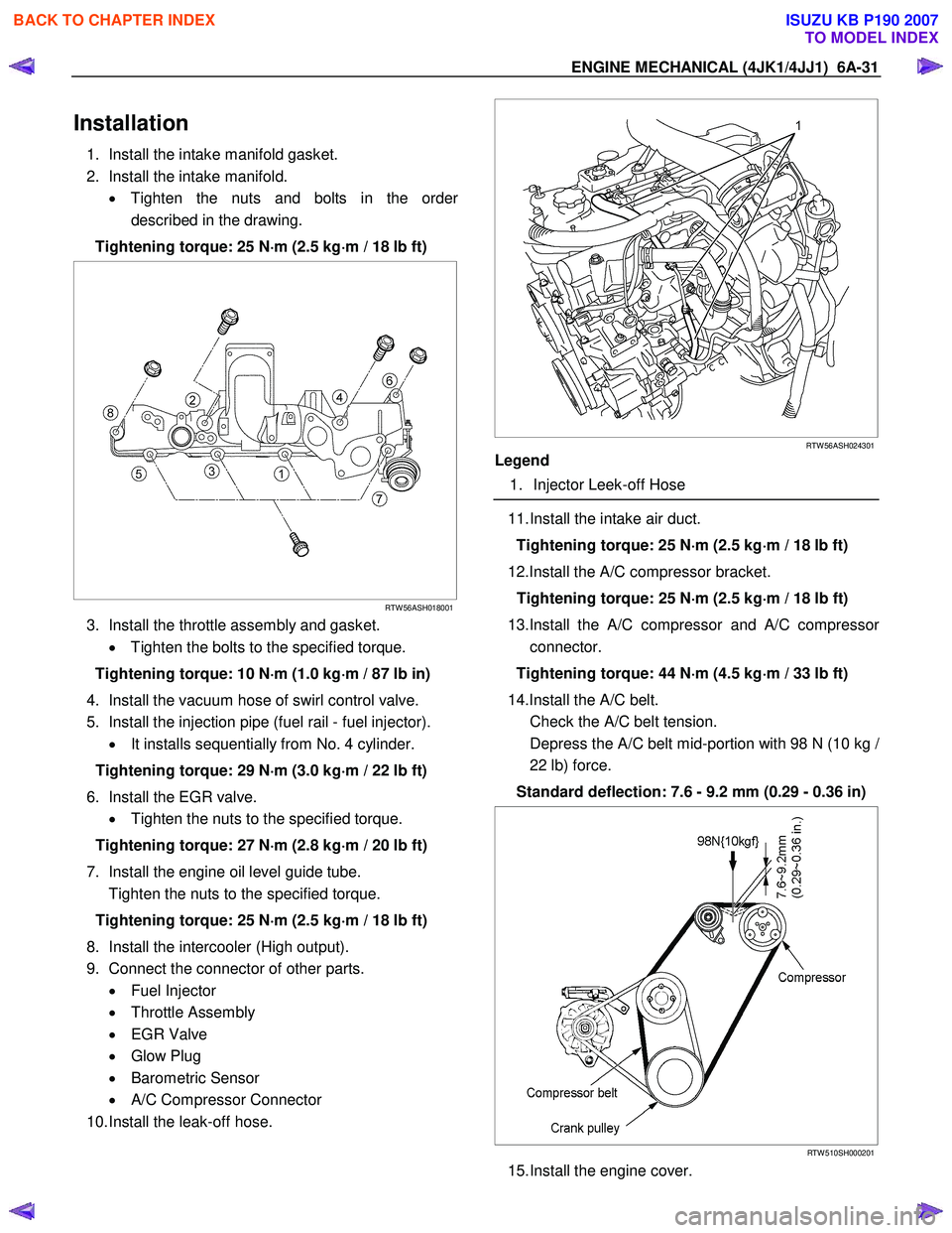
2. Install the intake manifold. • Tighten the nuts and bolts in the orde
r
described in the drawing.
Tightening torque: 25 N ⋅
⋅⋅
⋅
m (2.5 kg ⋅
⋅⋅
⋅
m / 18 lb ft)
RTW 56ASH018001
3. Install the throttle assembly and gasket.
• Tighten the bolts to the specified torque.
Tightening torque: 10 N ⋅
⋅⋅
⋅
m (1.0 kg ⋅
⋅⋅
⋅
m / 87 lb in)
4. Install the vacuum hose of swirl control valve.
5. Install the injection pipe (fuel rail - fuel injector). • It installs sequentially from No. 4 cylinder.
Tightening torque: 29 N ⋅
⋅⋅
⋅
m (3.0 kg ⋅
⋅⋅
⋅
m / 22 lb ft)
6. Install the EGR valve. • Tighten the nuts to the specified torque.
Tightening torque: 27 N ⋅
⋅⋅
⋅
m (2.8 kg ⋅
⋅⋅
⋅
m / 20 lb ft)
7. Install the engine oil level guide tube.
Tighten the nuts to the specified torque.
Tightening torque: 25 N ⋅
⋅⋅
⋅
m (2.5 kg ⋅
⋅⋅
⋅
m / 18 lb ft)
8. Install the intercooler (High output).
9. Connect the connector of other parts. • Fuel Injector
• Throttle Assembly
• EGR Valve
• Glow Plug
• Barometric Sensor
• A/C Compressor Connector
10. Install the leak-off hose.
RTW 56ASH024301
Legend
1. Injector Leek-off Hose
11. Install the intake air duct.
Tightening torque: 25 N ⋅
⋅⋅
⋅
m (2.5 kg ⋅
⋅⋅
⋅
m / 18 lb ft)
12.Install the A/C compressor bracket. Tightening torque: 25 N ⋅
⋅⋅
⋅
m (2.5 kg ⋅
⋅⋅
⋅
m / 18 lb ft)
13.Install the A/C compressor and A/C compresso
r
connector.
Tightening torque: 44 N ⋅
⋅⋅
⋅
m (4.5 kg ⋅
⋅⋅
⋅
m / 33 lb ft)
14.Install the A/C belt.
Check the A/C belt tension.
Depress the A/C belt mid-portion with 98 N (10 kg
/
22 lb) force.
Standard deflection: 7.6 - 9.2 mm (0.29 - 0.36 in)
RTW 510SH000201
15. Install the engine cover.
BACK TO CHAPTER INDEX
TO MODEL INDEX
ISUZU KB P190 2007
Page 1396 of 6020
6A-36 ENGINE MECHANICAL (4JK1/4JJ1)
Inspection
• Inspection of the exhaust manifold. Inspect the
plane surface of the plane on which the
manifold and the cylinder head are to be
installed.
Manifold installation plane surface mm (in)
Standard 0.3 (0.01) or lower
Limit 0.5 (0.02)
Note:
If the plane surface exceeds the limit, replace it.
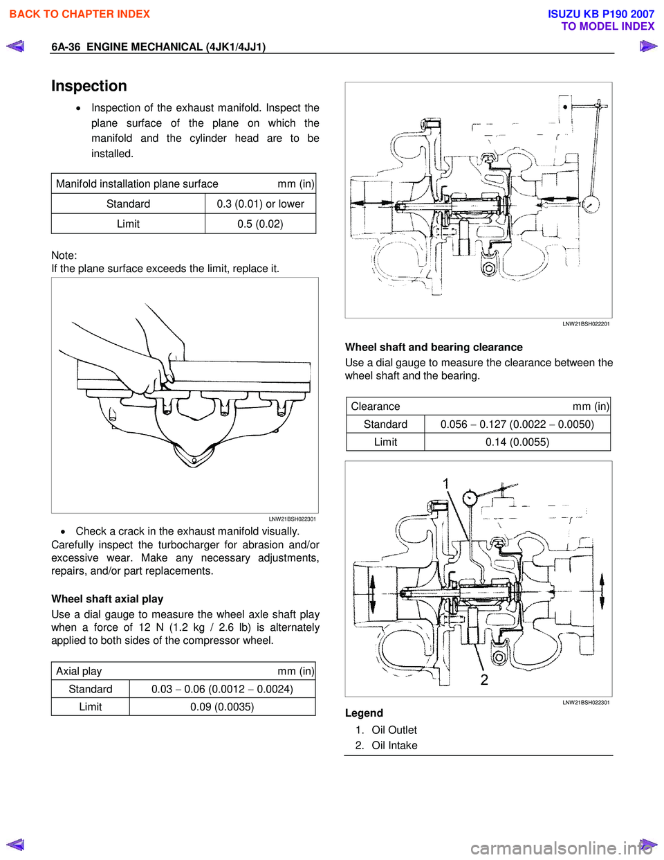
LNW 21BSH022301
• Check a crack in the exhaust manifold visually.
Carefully inspect the turbocharger for abrasion and/o
r
excessive wear. Make any necessary adjustments,
repairs, and/or part replacements.
Wheel shaft axial play
Use a dial gauge to measure the wheel axle shaft pla
y
when a force of 12 N (1.2 kg / 2.6 lb) is alternately
applied to both sides of the compressor wheel.
Axial play mm (in)
Standard 0.03 − 0.06 (0.0012 − 0.0024)
Limit 0.09 (0.0035)
LNW 21BSH022201
Wheel shaft and bearing clearance
Use a dial gauge to measure the clearance between the
wheel shaft and the bearing.
Clearance mm (in)
Standard 0.056 − 0.127 (0.0022 − 0.0050)
Limit 0.14 (0.0055)
LNW 21BSH022301
Legend
1. Oil Outlet
2. Oil Intake
BACK TO CHAPTER INDEX
TO MODEL INDEX
ISUZU KB P190 2007
Page 1404 of 6020
6A-44 ENGINE MECHANICAL (4JK1/4JJ1)
3. Place a vernier caliper on the end of the control
rod of actuator. Release the vacuum pressure and
check the control rod moves. Measure the length
of the control rod moving.
Standard length mm (in)
12 (0.48)
Installation
1. Install the gasket and the turbocharger to the
exhaust manifold. Temporarily tighten nuts.
2. Install the oil feed and return pipe and temporaril
y
tighten.
3. Tighten the turbocharger nuts to the specified torque.
Tightening torque: 27 N ⋅
⋅⋅
⋅
m (2.8 kg ⋅
⋅⋅
⋅
m / 20 lb ft)
4. Tighten the oil feed and return pipe bolts and nuts to the specified torque.
Tightening torque (Turbocharger side): 10 N ⋅
⋅⋅
⋅
m (1.0 kg ⋅
⋅⋅
⋅
m / 87 lb in)
Tightening torque (Crank case side): 25 N ⋅
⋅⋅
⋅
m (2.5 kg ⋅
⋅⋅
⋅
m / 18 lb ft)
5. Install the water feed and return pipe to the turbocharger.
Tightening torque: 25 N ⋅
⋅⋅
⋅
m (2.5 kg ⋅
⋅⋅
⋅
m / 18 lb ft)
6. Install the heat protector to the turbocharger. Tightening torque: 10 N ⋅
⋅⋅
⋅
m (1.0 kg ⋅
⋅⋅
⋅
m / 18 lb ft)
7. Install the turbocharger bracket.
8. Install the catalyst converter.
Tighten the nuts to the specified torque.
Tightening torque: 27 N ⋅
⋅⋅
⋅
m (2.8 kg ⋅
⋅⋅
⋅
m / 20 lb ft)
9. Install the mud cover of front RH fender skirt (4 ×4
only).
10. Install the front exhaust pipe.
Tighten the nuts to the specified torque.
Tightening torque
Exhaust Manifold Side: 67 N⋅
⋅⋅
⋅m (6.8 kg⋅
⋅⋅
⋅m / 49 lb ft)
Exhaust Pipe Side: 43 N
⋅
⋅⋅
⋅
m (4.4 kg ⋅
⋅⋅
⋅
m / 32lb ft)
11. Install the intercooler. • Install the intercooler.
• Install the two intake hoses.
• Connect the BARO sensor harness connector.
12. Install the intake duct between the turbocharge
r
and the air cleaner.
Tightening torque: 6 N ⋅
⋅⋅
⋅
m (0.6 kg ⋅
⋅⋅
⋅
m / 52 lb in)
13.Replenish the coolant.
BACK TO CHAPTER INDEX
TO MODEL INDEX
ISUZU KB P190 2007
Page 1417 of 6020
ENGINE MECHANICAL (4JK1/4JJ1) 6A-57
6. Remove the M6 bolt from the idle gear A.
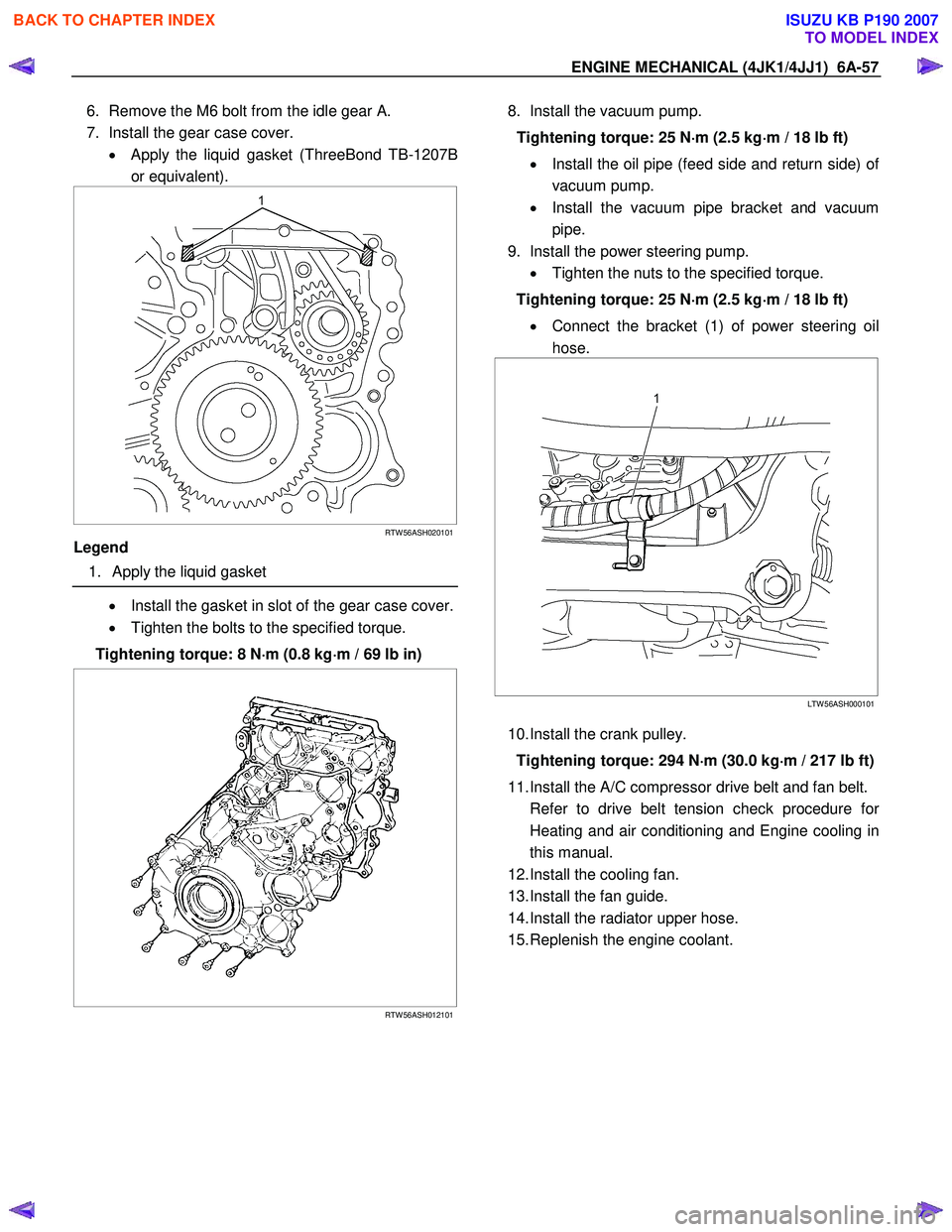
7. Install the gear case cover. • Apply the liquid gasket (ThreeBond TB-1207B
or equivalent).
RTW 56ASH020101
Legend
1. Apply the liquid gasket
• Install the gasket in slot of the gear case cover.
• Tighten the bolts to the specified torque.
Tightening torque: 8 N ⋅
⋅⋅
⋅
m (0.8 kg ⋅
⋅⋅
⋅
m / 69 lb in)
RTW 56ASH012101
8. Install the vacuum pump.
Tightening torque: 25 N ⋅
⋅⋅
⋅
m (2.5 kg ⋅
⋅⋅
⋅
m / 18 lb ft)
• Install the oil pipe (feed side and return side) o
f
vacuum pump.
• Install the vacuum pipe bracket and vacuum
pipe.
9. Install the power steering pump. • Tighten the nuts to the specified torque.
Tightening torque: 25 N ⋅
⋅⋅
⋅
m (2.5 kg ⋅
⋅⋅
⋅
m / 18 lb ft)
• Connect the bracket (1) of power steering oil
hose.
LTW 56ASH000101
10. Install the crank pulley.
Tightening torque: 294 N ⋅
⋅⋅
⋅
m (30.0 kg ⋅
⋅⋅
⋅
m / 217 lb ft)
11. Install the A/C compressor drive belt and fan belt.
Refer to drive belt tension check procedure fo
r
Heating and air conditioning and Engine cooling in
this manual.
12. Install the cooling fan.
13. Install the fan guide.
14. Install the radiator upper hose.
15. Replenish the engine coolant.
BACK TO CHAPTER INDEX
TO MODEL INDEX
ISUZU KB P190 2007
Page 1423 of 6020
ENGINE MECHANICAL (4JK1/4JJ1) 6A-63
LNW 21BSH020501
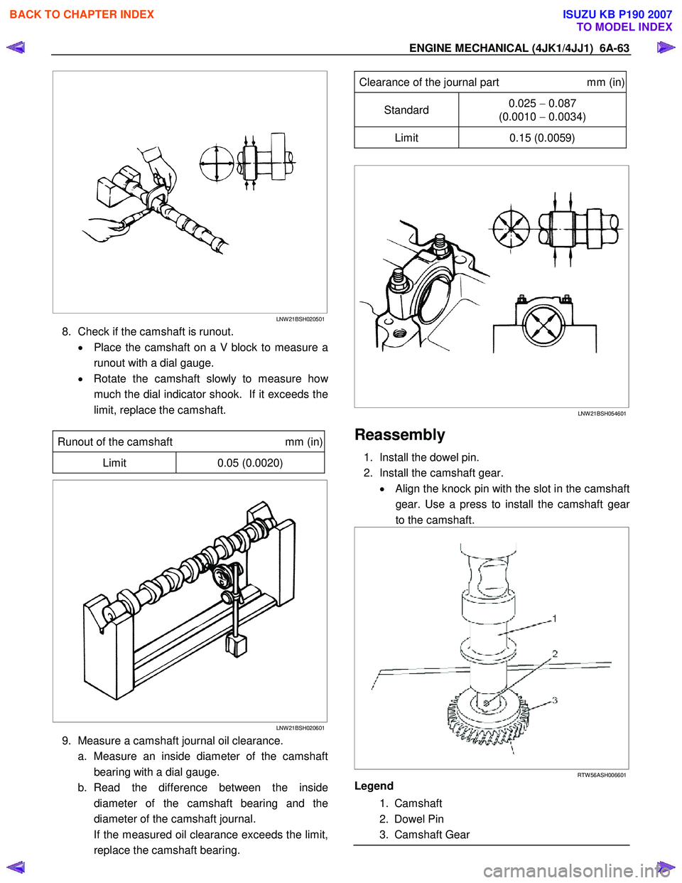
8. Check if the camshaft is runout.
• Place the camshaft on a V block to measure a
runout with a dial gauge.
• Rotate the camshaft slowly to measure ho
w
much the dial indicator shook. If it exceeds the
limit, replace the camshaft.
Runout of the camshaft mm (in)
Limit 0.05 (0.0020)
LNW 21BSH020601
9. Measure a camshaft journal oil clearance.
a. Measure an inside diameter of the camshaft bearing with a dial gauge.
b. Read the difference between the inside diameter of the camshaft bearing and the
diameter of the camshaft journal.
If the measured oil clearance exceeds the limit, replace the camshaft bearing.
Clearance of the journal part mm (in)
Standard 0.025
− 0.087
(0.0010 − 0.0034)
Limit 0.15 (0.0059)
LNW 21BSH054601
Reassembly
1. Install the dowel pin.
2. Install the camshaft gear. • Align the knock pin with the slot in the camshaft
gear. Use a press to install the camshaft gea
r
to the camshaft.
RTW 56ASH006601
Legend
1. Camshaft
2. Dowel Pin
3. Camshaft Gear
BACK TO CHAPTER INDEX
TO MODEL INDEX
ISUZU KB P190 2007
Page 1425 of 6020
ENGINE MECHANICAL (4JK1/4JJ1) 6A-65
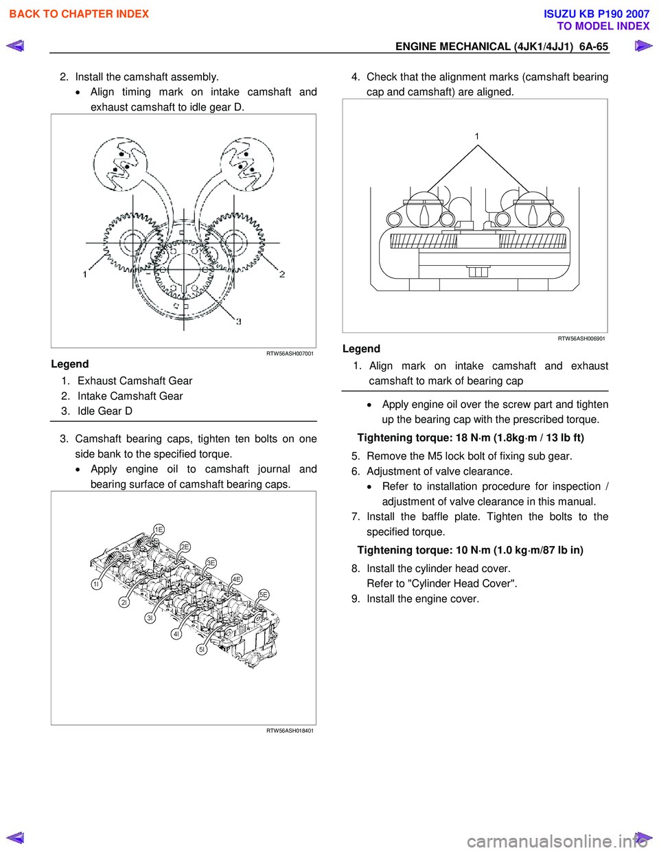
2. Install the camshaft assembly.
• Align timing mark on intake camshaft and
exhaust camshaft to idle gear D.
RTW 56ASH007001
Legend
1. Exhaust Camshaft Gear
2. Intake Camshaft Gear
3. Idle Gear D
3. Camshaft bearing caps, tighten ten bolts on one
side bank to the specified torque.
• Apply engine oil to camshaft journal and
bearing surface of camshaft bearing caps.
RTW 56ASH018401
4. Check that the alignment marks (camshaft bearing
cap and camshaft) are aligned.
RTW 56ASH006901
Legend
1.
Align mark on intake camshaft and exhaust
camshaft to mark of bearing cap
• Apply engine oil over the screw part and tighten
up the bearing cap with the prescribed torque.
Tightening torque: 18 N ⋅
⋅⋅
⋅
m (1.8kg ⋅
⋅⋅
⋅
m / 13 lb ft)
5. Remove the M5 lock bolt of fixing sub gear.
6. Adjustment of valve clearance. • Refer to installation procedure for inspection
/
adjustment of valve clearance in this manual.
7. Install the baffle plate. Tighten the bolts to the specified torque.
Tightening torque: 10 N ⋅
⋅⋅
⋅
m (1.0 kg ⋅
⋅⋅
⋅
m/87 lb in)
8. Install the cylinder head cover.
Refer to "Cylinder Head Cover".
9. Install the engine cover.
BACK TO CHAPTER INDEX
TO MODEL INDEX
ISUZU KB P190 2007
Page 1430 of 6020
6A-70 ENGINE MECHANICAL (4JK1/4JJ1)
Installation
1. Install the spring lower seat.
2. Install the valve stem oil seal. •
Apply engine oil over the peripheral part of the
valve guide and install the oil seal by using a
valve stem seal installer.
Note:
After installing the valve stem oil seal, check if it is
inserted nice and deep and the oil seal is not tilted o
r
the garter spring has not come off.
Special tool
Valve stem seal installer: 5-8840-2817-0
RTW 56ASH013701
3. Install the valve spring.
4. Install the spring upper seat.
5. Install the split collar.
• Use a replacer to compress the valve spring
and install the split collar.
Special tool
Valve spring replacer: 5-8840-2818-0 (1)
Pivot assembly: 5-8840-2819-0 (2)
RTW 56ASH012301
Note:
Move it up and down to check if it moves smoothly.
6. Install the cylinder head.
Refer to “Cylinder Head”.
BACK TO CHAPTER INDEX
TO MODEL INDEX
ISUZU KB P190 2007
Page 1481 of 6020
ENGINE MECHANICAL (4JK1/4JJ1) 6A-121
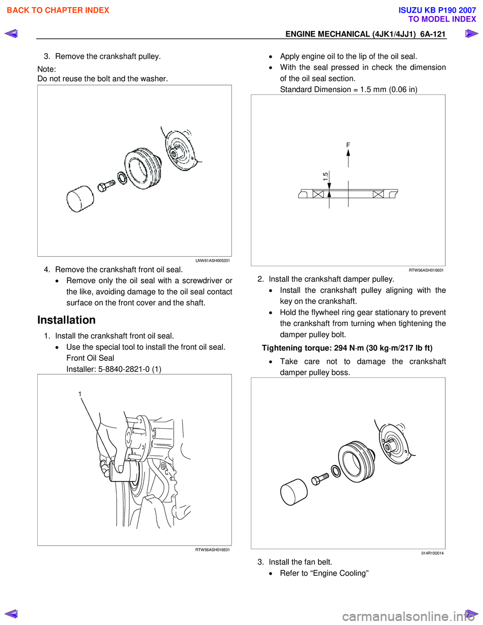
3. Remove the crankshaft pulley.
Note:
Do not reuse the bolt and the washer.
LNW 61ASH005301
4. Remove the crankshaft front oil seal.
• Remove only the oil seal with a screwdriver o
r
the like, avoiding damage to the oil seal contact
surface on the front cover and the shaft.
Installation
1. Install the crankshaft front oil seal. • Use the special tool to install the front oil seal.
Front Oil Seal
Installer: 5-8840-2821-0 (1)
RTW 56ASH016501
• Apply engine oil to the lip of the oil seal.
• W ith the seal pressed in check the dimension
of the oil seal section.
Standard Dimension = 1.5 mm (0.06 in)
RTW 56ASH016601
2. Install the crankshaft damper pulley.
• Install the crankshaft pulley aligning with the
key on the crankshaft.
• Hold the flywheel ring gear stationary to prevent
the crankshaft from turning when tightening the
damper pulley bolt.
Tightening torque: 294 N ⋅
⋅⋅
⋅
m (30 kg ⋅
⋅⋅
⋅
m/217 lb ft)
• Take care not to damage the crankshaft
damper pulley boss.
014R100014
3. Install the fan belt.
• Refer to “Engine Cooling”
BACK TO CHAPTER INDEX
TO MODEL INDEX
ISUZU KB P190 2007