2007 ISUZU KB P190 check oil
[x] Cancel search: check oilPage 1489 of 6020
ENGINE MECHANICAL (4JK1/4JJ1) 6A-129
015RY00012
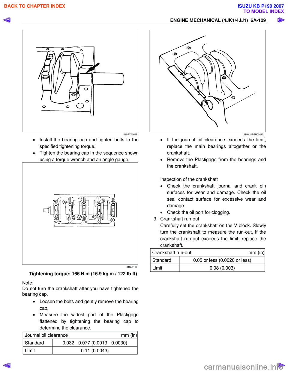
• Install the bearing cap and tighten bolts to the
specified tightening torque.
• Tighten the bearing cap in the sequence shown
using a torque wrench and an angle gauge.
015LX129
Tightening torque: 166 N ⋅
⋅⋅
⋅
m (16.9 kg ⋅
⋅⋅
⋅
m / 122 lb ft)
Note:
Do not turn the crankshaft after you have tightened the
bearing cap.
• Loosen the bolts and gently remove the bearing
cap.
• Measure the widest part of the Plastigage
flattened by tightening the bearing cap to
determine the clearance.
Journal oil clearance mm (in)
Standard 0.032 - 0.077 (0.0013 - 0.0030)
Limit 0.11 (0.0043)
LNW 21BSH024401
•
If the journal oil clearance exceeds the limit,
replace the main bearings altogether or the
crankshaft.
• Remove the Plastigage from the bearings and
the crankshaft.
Inspection of the crankshaft
• Check the crankshaft journal and crank pin
surfaces for wear and damage. Check the oil
seal contact surface for excessive wear and
damage.
• Check the oil port for clogging.
3. Crankshaft run-out
Carefully set the crankshaft on the V block. Slowl
y
turn the crankshaft to measure the run-out. If the
crankshaft run-out exceeds the limit, replace the
crankshaft.
Crankshaft run-out mm (in)
Standard 0.05 or less (0.0020 or less)
Limit 0.08 (0.003)
BACK TO CHAPTER INDEX
TO MODEL INDEX
ISUZU KB P190 2007
Page 1493 of 6020
ENGINE MECHANICAL (4JK1/4JJ1) 6A-133
015LX115
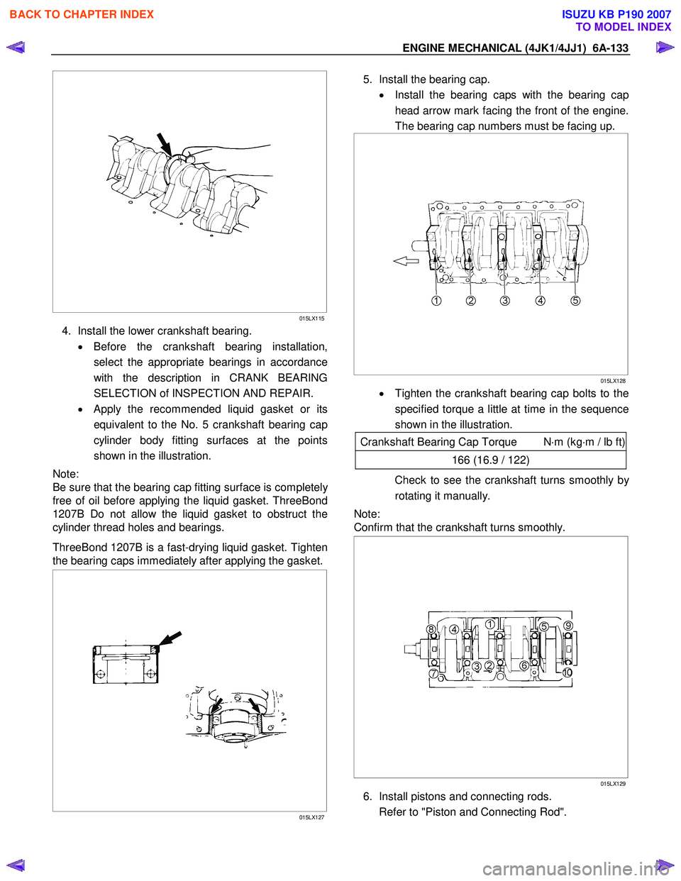
4. Install the lower crankshaft bearing.
• Before the crankshaft bearing installation,
select the appropriate bearings in accordance
with the description in CRANK BEARING
SELECTION of INSPECTION AND REPAIR.
• Apply the recommended liquid gasket or its
equivalent to the No. 5 crankshaft bearing cap
cylinder body fitting surfaces at the points
shown in the illustration.
Note:
Be sure that the bearing cap fitting surface is completel
y
free of oil before applying the liquid gasket. ThreeBond
1207B Do not allow the liquid gasket to obstruct the
cylinder thread holes and bearings.
ThreeBond 1207B is a fast-drying liquid gasket. Tighten
the bearing caps immediately after applying the gasket.
015LX127
5. Install the bearing cap.
• Install the bearing caps with the bearing cap
head arrow mark facing the front of the engine.
The bearing cap numbers must be facing up.
015LX128
• Tighten the crankshaft bearing cap bolts to the
specified torque a little at time in the sequence
shown in the illustration.
Crankshaft Bearing Cap Torque N ⋅m (kg ⋅m / lb ft)
166 (16.9 / 122)
Check to see the crankshaft turns smoothly by
rotating it manually.
Note:
Confirm that the crankshaft turns smoothly.
015LX129
6. Install pistons and connecting rods.
Refer to "Piston and Connecting Rod".
BACK TO CHAPTER INDEX
TO MODEL INDEX
ISUZU KB P190 2007
Page 1501 of 6020
ENGINE MECHANICAL (4JK1/4JJ1) 6A-141
Functional Check
Oil pressure check
1. Check whether the engine oil is contaminated with
dirt, light oil, or water. If contaminated with dirt,
light oil, or water (after examining the cause and
taking the appropriate measures for light oil o
r
water contamination), replace the oil.
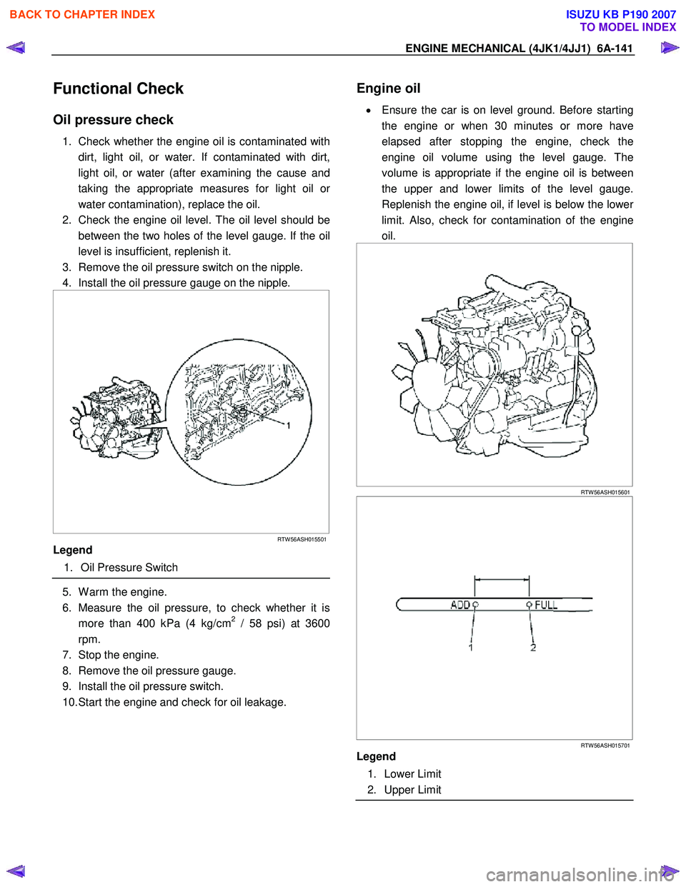
2. Check the engine oil level. The oil level should be between the two holes of the level gauge. If the oil
level is insufficient, replenish it.
3. Remove the oil pressure switch on the nipple.
4. Install the oil pressure gauge on the nipple.
RTW 56ASH015501
Legend
1. Oil Pressure Switch
5. W arm the engine.
6. Measure the oil pressure, to check whether it is more than 400 kPa (4 kg/cm
2 / 58 psi) at 3600
rpm.
7. Stop the engine.
8. Remove the oil pressure gauge.
9. Install the oil pressure switch.
10. Start the engine and check for oil leakage.
Engine oil
•
Ensure the car is on level ground. Before starting
the engine or when 30 minutes or more have
elapsed after stopping the engine, check the
engine oil volume using the level gauge. The
volume is appropriate if the engine oil is between
the upper and lower limits of the level gauge.
Replenish the engine oil, if level is below the lowe
r
limit. Also, check for contamination of the engine
oil.
RTW 56ASH015601
RTW 56ASH015701
Legend
1. Lower Limit
2. Upper Limit
BACK TO CHAPTER INDEX
TO MODEL INDEX
ISUZU KB P190 2007
Page 1520 of 6020
6A-160 ENGINE MECHANICAL (4JK1/4JJ1)
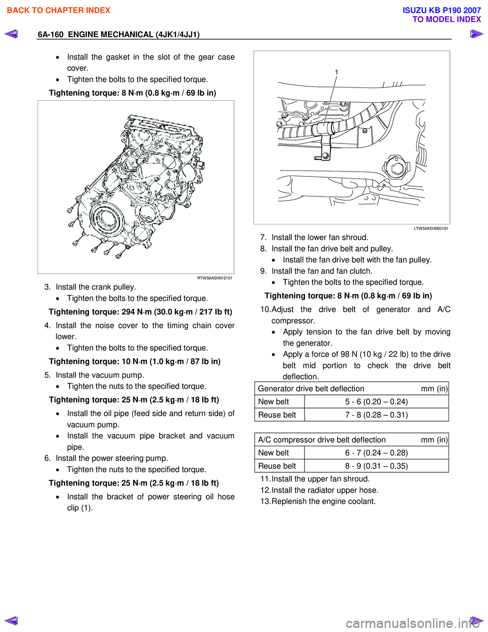
• Install the gasket in the slot of the gear case
cover.
• Tighten the bolts to the specified torque.
Tightening torque: 8 N ⋅
⋅⋅
⋅
m (0.8 kg ⋅
⋅⋅
⋅
m / 69 lb in)
RTW 56ASH012101
3. Install the crank pulley.
• Tighten the bolts to the specified torque.
Tightening torque: 294 N ⋅
⋅⋅
⋅
m (30.0 kg ⋅
⋅⋅
⋅
m / 217 lb ft)
4. Install the noise cover to the timing chain cove
r
lower.
• Tighten the bolts to the specified torque.
Tightening torque: 10 N ⋅
⋅⋅
⋅
m (1.0 kg ⋅
⋅⋅
⋅
m / 87 lb in)
5. Install the vacuum pump. • Tighten the nuts to the specified torque.
Tightening torque: 25 N ⋅
⋅⋅
⋅
m (2.5 kg ⋅
⋅⋅
⋅
m / 18 lb ft)
• Install the oil pipe (feed side and return side) o
f
vacuum pump.
• Install the vacuum pipe bracket and vacuum
pipe.
6. Install the power steering pump. • Tighten the nuts to the specified torque.
Tightening torque: 25 N ⋅
⋅⋅
⋅
m (2.5 kg ⋅
⋅⋅
⋅
m / 18 lb ft)
• Install the bracket of power steering oil hose
clip (1).
LTW 56ASH000101
7. Install the lower fan shroud.
8. Install the fan drive belt and pulley. • Install the fan drive belt with the fan pulley.
9. Install the fan and fan clutch. • Tighten the bolts to the specified torque.
Tightening torque: 8 N ⋅
⋅⋅
⋅
m (0.8 kg ⋅
⋅⋅
⋅
m / 69 lb in)
10.
Adjust the drive belt of generator and A/C
compressor.
• Apply tension to the fan drive belt by moving
the generator.
•
Apply a force of 98 N (10 kg / 22 lb) to the drive
belt mid portion to check the drive belt
deflection.
Generator drive belt deflection mm (in)
New belt 5 - 6 (0.20 – 0.24)
Reuse belt 7 - 8 (0.28 – 0.31)
A/C compressor drive belt deflection mm (in)
New belt 6 - 7 (0.24 – 0.28)
Reuse belt 8 - 9 (0.31 – 0.35)
11. Install the upper fan shroud.
12. Install the radiator upper hose.
13. Replenish the engine coolant.
BACK TO CHAPTER INDEX
TO MODEL INDEX
ISUZU KB P190 2007
Page 1522 of 6020
6A-162 ENGINE MECHANICAL (4JK1/4JJ1)
Removal
1. Remove the oil pressure SW .
2. Remove the nipple; oil gallery.
3. Remove the nipple; oil pressure warning SW and gasket.
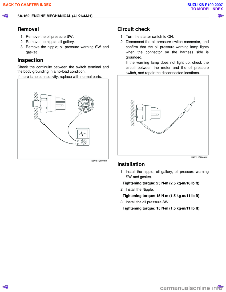
Inspection
Check the continuity between the switch terminal and
the body grounding in a no-load condition.
If there is no connectivity, replace with normal parts.
LNW 21HSH003301
Circuit check
1. Turn the starter switch to ON.
2. Disconnect the oil pressure switch connector, and confirm that the oil pressure-warning lamp lights
when the connector on the harness side is
grounded.
If the warning lamp does not light up, check the circuit between the meter and the oil pressure
switch, and repair the disconnected locations.
LNW 21HSH003401
Installation
1. Install the nipple; oil gallery, oil pressure warning
SW and gasket.
Tightening torque: 25 N ⋅
⋅⋅
⋅
m (2.5 kg ⋅
⋅⋅
⋅
m/18 lb ft)
2. Install the Nipple. Tightening torque: 15 N ⋅
⋅⋅
⋅
m (1.5 kg ⋅
⋅⋅
⋅
m/11 lb ft)
3. Install the oil pressure SW . Tightening torque: 15 N ⋅
⋅⋅
⋅
m (1.5 kg ⋅
⋅⋅
⋅
m/11 lb ft)
BACK TO CHAPTER INDEX
TO MODEL INDEX
ISUZU KB P190 2007
Page 1530 of 6020
ENGINE COOLING (4JK1/4JJ1) 6B-7
Draining and Refilling Cooling System
Before draining the cooling system, inspect the system
and perform any necessary service to ensure that it is
clean, does not leak and is in proper working order.
The engine coolant (EC) level should be between the
“MIN" and “MAX" lines of the reserve tank when the
engine is cold. If low, check for leakage and add EC up
to the “MAX" line.
There should not be any excessive deposit of rust o
r
scales around the radiator cap or radiator filler hole, and
the EC should also be free from oil.
Replace the EC if excessively dirty.
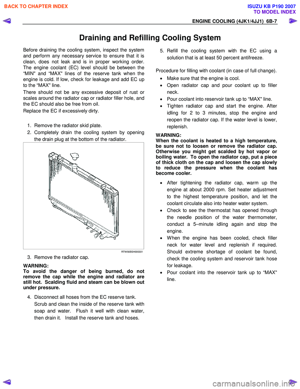
1. Remove the radiator skid plate.
2. Completely drain the cooling system by opening the drain plug at the bottom of the radiator.
RTW 56BSH000301
3. Remove the radiator cap.
WARNING:
To avoid the danger of being burned, do not
remove the cap while the engine and radiator are
still hot. Scalding fluid and steam can be blown out
under pressure.
4. Disconnect all hoses from the EC reserve tank.
Scrub and clean the inside of the reserve tank with soap and water. Flush it well with clean water,
then drain it. Install the reserve tank and hoses.
5. Refill the cooling system with the EC using a
solution that is at least 50 percent antifreeze.
Procedure for filling with coolant (in case of full change).
• Make sure that the engine is cool.
• Open radiator cap and pour coolant up to fille
r
neck.
• Pour coolant into reservoir tank up to “MAX" line.
• Tighten radiator cap and start the engine. Afte
r
idling for 2 to 3 minutes, stop the engine and
reopen the radiator cap. If the water level is lower,
replenish.
WARNING:
When the coolant is heated to a high temperature,
be sure not to loosen or remove the radiator cap.
Otherwise you might get scalded by hot vapor o
r
boiling water. To open the radiator cap, put a piece
of thick cloth on the cap and loosen the cap slowly
to reduce the pressure when the coolant has
become cooler.
• After tightening the radiator cap, warm up the
engine at about 2000 rpm. Set heater adjustment
to the highest temperature position, and let the
coolant circulate also into heater water system.
• Check to see the thermostat has opened through
the needle position of the water thermometer,
conduct a 5–minute idling again and stop the
engine.
• W hen the engine has been cooled, check fille
r
neck for water level and replenish if required.
Should extreme shortage of coolant be found,
check the cooling system and reservoir tank hose
for leakage.
• Pour coolant into the reservoir tank up to “MAX"
line.
BACK TO CHAPTER INDEX
TO MODEL INDEX
ISUZU KB P190 2007
Page 1554 of 6020
FUEL SYSTEM (4JK1/4JJ1) 6C-13
Fuel Filter Element
Removal
1. Detach the drain hose on the lower part of the fuel
filter or the drain plug, loosen the air bleed plug,
and drain the fuel from the fuel filter.
2. Detach the water-in-fuel switch harness.
3. Turn the element case counterclockwise to detach, and remove the filter element.
4. Replace the O-ring and confirm the snap-fit position, and fit a new filter element inside the
element case.
NOTE
It is strongly advisable to use the ISUZU/GM genuine
fuel filter for replacement.
RTW 76CSH000901
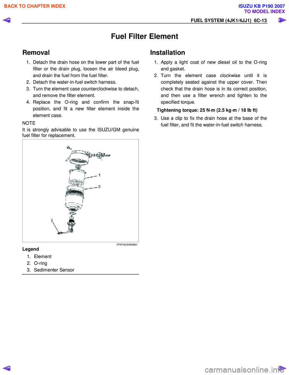
Legend
1. Element
2. O-ring
3. Sedimenter Sensor
Installation
1. Apply a light coat of new diesel oil to the O-ring
and gasket.
2. Turn the element case clockwise until it is completely seated against the upper cover. Then
check that the drain hose is in its correct position,
and then use a filter wrench and tighten to the
specified torque.
Tightening torque: 25 N ⋅
⋅⋅
⋅
m (2.5 kg ⋅
⋅⋅
⋅
m / 18 lb ft)
3. Use a clip to fix the drain hose at the base of the fuel filter, and fit the water-in-fuel switch harness.
BACK TO CHAPTER INDEX
TO MODEL INDEX
ISUZU KB P190 2007
Page 1556 of 6020
FUEL SYSTEM (4JK1/4JJ1) 6C-15
The fuel system consists of many tiny holes and spaces
that allow the movement of fuel from one place to
another. These holes and spaces are milled to
extremely high precision. This is especially true of the
fuel injector.
The fuel injector is very sensitive to foreign material.
Foreign material will result in fuel system breakdown.
Exercise great care not to allow the entry of foreign
material into the fuel system or fuel injector during the
removal and installation procedure.
Note: To avoid electric shock;
Set the switch to the 'OFF' position and disconnect the
negative battery cable before checking or repairing the
fuel injector, wiring or/and connectors.
Removal
1. Remove the cylinder head cover.
Refer to the removal procedure for the cylinde
r
head cover in this manual.
Remove the attachment bolt of the engine oil gauge
guide tube.
2. Loosen the fuel injector clamp fixing bolts and
remove the fuel injector.
If the fuel injector is difficult to remove, use the remover. Use a screwdriver to force the fuel
injector clamp off the fuel injector.
Note: Do not remove the fuel injector sleeve.
Note: Cover the areas exposed during parts removal to
prevent the entry of foreign material into the fuel
system.
3. Mark each fuel injector with the number of the cylinder from which it was removed. Store the fuel
injector in a safe place. Position the fuel injector so
that the nozzle is protected.
Note: Do not tamper with the electromagnetic portion of
the fuel injector. Reduced electromagnetic function will
result in injector failure.
Note: After replacement of the fuel injector, perform the
following procedure.
• All fuel injectors are replaced:
Remove the fuel injector ID code label on the cylinder head cover.
• Any fuel injector(s) is replaced:
Black out the replaced cylinder of the fuel injecto
r
ID code on the fuel injector ID code label with a
marking pen or equivalent.
Installation
1. Install the new gasket and O-ring to each fuel
injector.
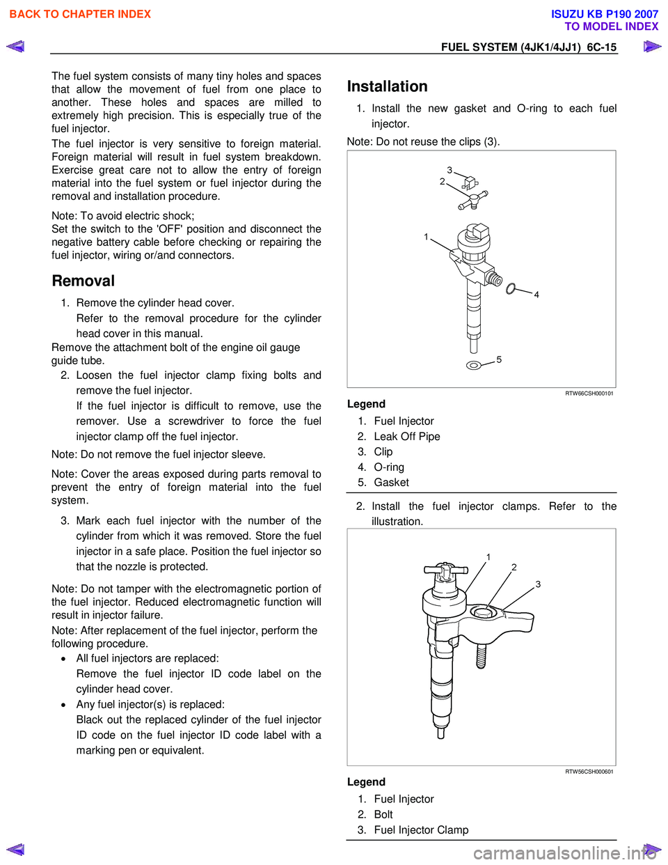
Note: Do not reuse the clips (3).
RTW 66CSH000101
Legend
1. Fuel Injector
2. Leak Off Pipe
3. Clip
4. O-ring
5. Gasket
2. Install the fuel injector clamps. Refer to the
illustration.
RTW 56CSH000601
Legend
1. Fuel Injector
2. Bolt
3. Fuel Injector Clamp
BACK TO CHAPTER INDEX
TO MODEL INDEX
ISUZU KB P190 2007