2007 ISUZU KB P190 service
[x] Cancel search: servicePage 1543 of 6020
6C-2 FUEL SYSTEM (4JK1/4JJ1)
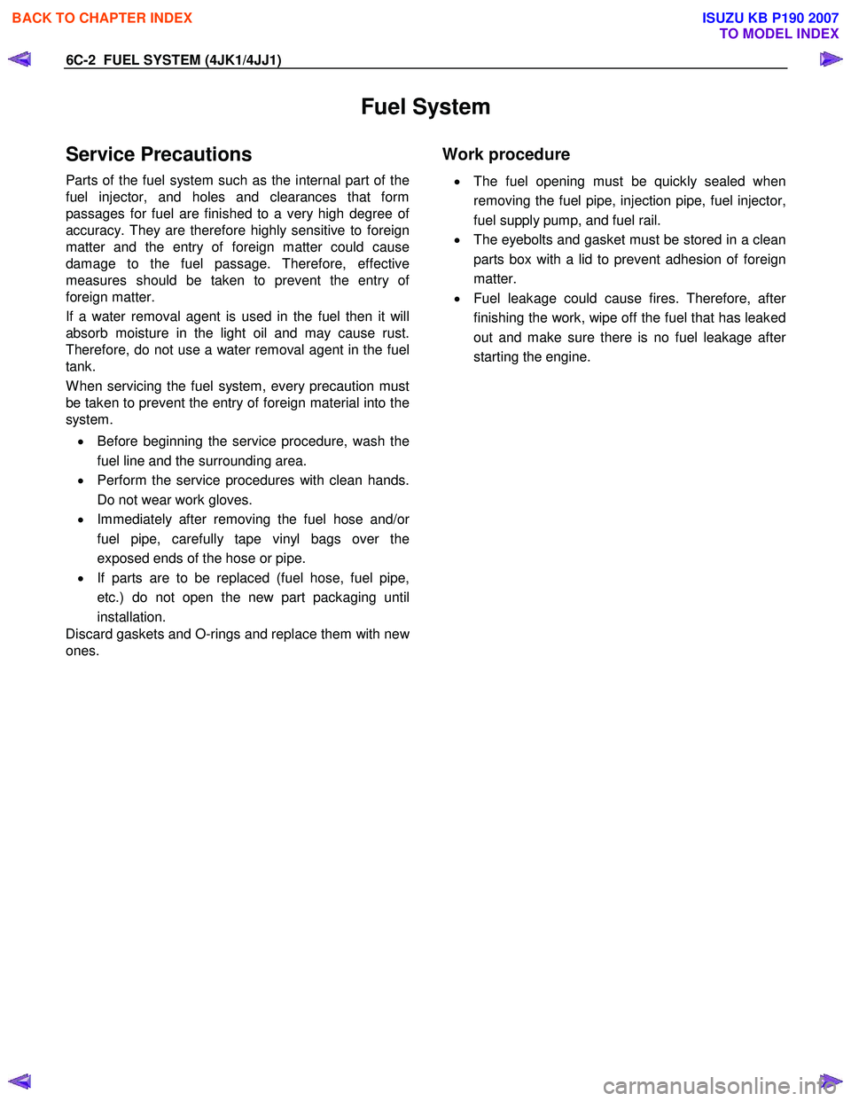
Fuel System
Service Precautions
Parts of the fuel system such as the internal part of the
fuel injector, and holes and clearances that form
passages for fuel are finished to a very high degree o
f
accuracy. They are therefore highly sensitive to foreign
matter and the entry of foreign matter could cause
damage to the fuel passage. Therefore, effective
measures should be taken to prevent the entry o
f
foreign matter.
If a water removal agent is used in the fuel then it will
absorb moisture in the light oil and may cause rust.
Therefore, do not use a water removal agent in the fuel
tank.
W hen servicing the fuel system, every precaution must
be taken to prevent the entry of foreign material into the
system.
• Before beginning the service procedure, wash the
fuel line and the surrounding area.
• Perform the service procedures with clean hands.
Do not wear work gloves.
• Immediately after removing the fuel hose and/o
r
fuel pipe, carefully tape vinyl bags over the
exposed ends of the hose or pipe.
• If parts are to be replaced (fuel hose, fuel pipe,
etc.) do not open the new part packaging until
installation.
Discard gaskets and O-rings and replace them with ne
w
ones.
Work procedure
•
The fuel opening must be quickly sealed when
removing the fuel pipe, injection pipe, fuel injector,
fuel supply pump, and fuel rail.
• The eyebolts and gasket must be stored in a clean
parts box with a lid to prevent adhesion of foreign
matter.
• Fuel leakage could cause fires. Therefore, afte
r
finishing the work, wipe off the fuel that has leaked
out and make sure there is no fuel leakage afte
r
starting the engine.
BACK TO CHAPTER INDEX
TO MODEL INDEX
ISUZU KB P190 2007
Page 1619 of 6020
6E-2 ENGINE CONTROL SYSTEM (4JK1/4JJ1)
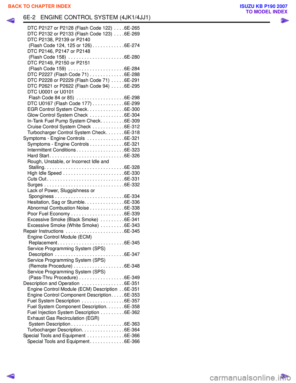
DTC P2127 or P2128 (Flash Code 122) . . . . 6E-265
DTC P2132 or P2133 (Flash Code 123) . . . . 6E-269
DTC P2138, P2139 or P2140 (Flash Code 124, 125 or 126) . . . . . . . . . . . . 6E-274
DTC P2146, P2147 or P2148 (Flash Code 158) . . . . . . . . . . . . . . . . . . . . . 6E-280
DTC P2149, P2150 or P2151 (Flash Code 159) . . . . . . . . . . . . . . . . . . . . . 6E-284
DTC P2227 (Flash Code 71) . . . . . . . . . . . . . 6E-288
DTC P2228 or P2229 (Flash Code 71) . . . . . 6E-291
DTC P2621 or P2622 (Flash Code 94) . . . . . 6E-295
DTC U0001 or U0101 Flash Code 84 or 85) . . . . . . . . . . . . . . . . . . 6E-298
DTC U0167 (Flash Code 177) . . . . . . . . . . . . 6E-299
EGR Control System Check. . . . . . . . . . . . . . 6E-300
Glow Control System Check . . . . . . . . . . . . . 6E-304
In-Tank Fuel Pump System Check . . . . . . . . . 6E-309
Cruise Control System Check . . . . . . . . . . . . 6E-312
Turbocharger Control System Check . . . . . . . 6E-318
Symptoms - Engine Controls . . . . . . . . . . . . . . 6E-321 Symptoms - Engine Controls . . . . . . . . . . . . . 6E-321
Intermittent Conditions . . . . . . . . . . . . . . . . . . 6E-323
Hard Start . . . . . . . . . . . . . . . . . . . . . . . . . . . . 6E-326
Rough, Unstable, or Incorrect Idle and Stalling. . . . . . . . . . . . . . . . . . . . . . . . . . . . . . 6E-328
High Idle Speed . . . . . . . . . . . . . . . . . . . . . . . 6E-330
Cuts Out . . . . . . . . . . . . . . . . . . . . . . . . . . . . . 6E-331
Surges . . . . . . . . . . . . . . . . . . . . . . . . . . . . . . 6E-332
Lack of Power, Sluggishness or Sponginess . . . . . . . . . . . . . . . . . . . . . . . . . . 6E-334
Hesitation, Sag or Stumble. . . . . . . . . . . . . . . 6E-336
Abnormal Combustion Noise . . . . . . . . . . . . . 6E-338
Poor Fuel Economy . . . . . . . . . . . . . . . . . . . . 6E-339
Excessive Smoke (Black Smoke) . . . . . . . . . 6E-341
Excessive Smoke (White Smoke) . . . . . . . . . 6E-343
Repair Instructions . . . . . . . . . . . . . . . . . . . . . . 6E-345 Engine Control Module (ECM) Replacement . . . . . . . . . . . . . . . . . . . . . . . . . 6E-345
Service Programming System (SPS) Description . . . . . . . . . . . . . . . . . . . . . . . . . . 6E-347
Service Programming System (SPS) (Remote Procedure) . . . . . . . . . . . . . . . . . . . 6E-348
Service Programming System (SPS) (Pass-Thru Procedure) . . . . . . . . . . . . . . . . . 6E-349
Description and Operation . . . . . . . . . . . . . . . . 6E-351 Engine Control Module (ECM) Description . . 6E-351
Engine Control Component Description . . . . . 6E-353
Fuel System Description . . . . . . . . . . . . . . . . 6E-357
Fuel System Component Description. . . . . . . 6E-358
Fuel Injection System Description . . . . . . . . . 6E-362
Exhaust Gas Recirculation (EGR) System Description . . . . . . . . . . . . . . . . . . . . 6E-363
Turbocharger Description . . . . . . . . . . . . . . . . 6E-364
Special Tools and Equipment . . . . . . . . . . . . . . 6E-366 Special Tools and Equipment . . . . . . . . . . . . . 6E-366
BACK TO CHAPTER INDEX
TO MODEL INDEX
ISUZU KB P190 2007
Page 1621 of 6020
6E-4 ENGINE CONTROL SYSTEM (4JK1/4JJ1)
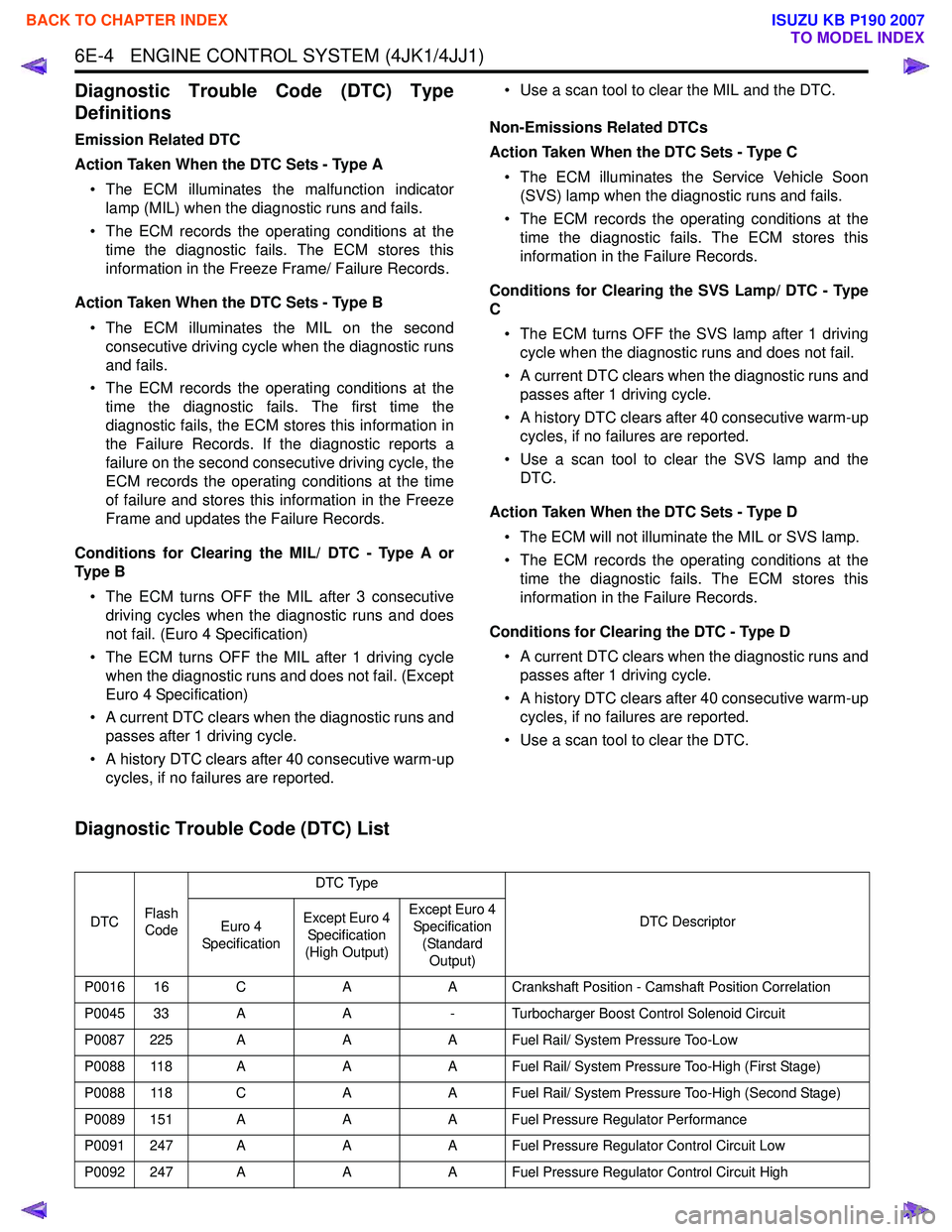
Diagnostic Trouble Code (DTC) Type
Definitions
Emission Related DTC
Action Taken When the DTC Sets - Type A • The ECM illuminates the malfunction indicator lamp (MIL) when the diagnostic runs and fails.
• The ECM records the operating conditions at the time the diagnostic fails. The ECM stores this
information in the Freeze Frame/ Failure Records.
Action Taken When the DTC Sets - Type B • The ECM illuminates the MIL on the second consecutive driving cycle when the diagnostic runs
and fails.
• The ECM records the operating conditions at the time the diagnostic fails. The first time the
diagnostic fails, the ECM stores this information in
the Failure Records. If the diagnostic reports a
failure on the second consecutive driving cycle, the
ECM records the operating conditions at the time
of failure and stores this information in the Freeze
Frame and updates the Failure Records.
Conditions for Clearing the MIL/ DTC - Type A or
Ty p e B
• The ECM turns OFF the MIL after 3 consecutive driving cycles when the diagnostic runs and does
not fail. (Euro 4 Specification)
• The ECM turns OFF the MIL after 1 driving cycle when the diagnostic runs and does not fail. (Except
Euro 4 Specification)
• A current DTC clears when the diagnostic runs and passes after 1 driving cycle.
• A history DTC clears after 40 consecutive warm-up cycles, if no failures are reported. • Use a scan tool to clear the MIL and the DTC.
Non-Emissions Related DTCs
Action Taken When the DTC Sets - Type C
• The ECM illuminates the Service Vehicle Soon (SVS) lamp when the diagnostic runs and fails.
• The ECM records the operating conditions at the time the diagnostic fails. The ECM stores this
information in the Failure Records.
Conditions for Clearing the SVS Lamp/ DTC - Type
C
• The ECM turns OFF the SVS lamp after 1 driving cycle when the diagnostic runs and does not fail.
• A current DTC clears when the diagnostic runs and passes after 1 driving cycle.
• A history DTC clears after 40 consecutive warm-up cycles, if no failures are reported.
• Use a scan tool to clear the SVS lamp and the DTC.
Action Taken When the DTC Sets - Type D • The ECM will not illuminate the MIL or SVS lamp.
• The ECM records the operating conditions at the time the diagnostic fails. The ECM stores this
information in the Failure Records.
Conditions for Clearing the DTC - Type D • A current DTC clears when the diagnostic runs and passes after 1 driving cycle.
• A history DTC clears after 40 consecutive warm-up cycles, if no failures are reported.
• Use a scan tool to clear the DTC.
Diagnostic Trouble Code (DTC) List
DTC Flash
Code DTC Type
DTC Descriptor
Euro 4
Specification Except Euro 4
Specification
(High Output) Except Euro 4
Specification
(Standard Output)
P0016 16 C AA Crankshaft Position - Camshaft Position Correlation
P0045 33 A A- Turbocharger Boost Control Solenoid Circuit
P0087 225 A AA Fuel Rail/ System Pressure Too-Low
P0088 118 A AA Fuel Rail/ System Pressure Too-High (First Stage)
P0088 118 C AA Fuel Rail/ System Pressure Too-High (Second Stage)
P0089 151 A AA Fuel Pressure Regulator Performance
P0091 247 A AA Fuel Pressure Regulator Control Circuit Low
P0092 247 A AA Fuel Pressure Regulator Control Circuit High
BACK TO CHAPTER INDEX
TO MODEL INDEX
ISUZU KB P190 2007
Page 1624 of 6020
ENGINE CONTROL SYSTEM (4JK1/4JJ1) 6E-7
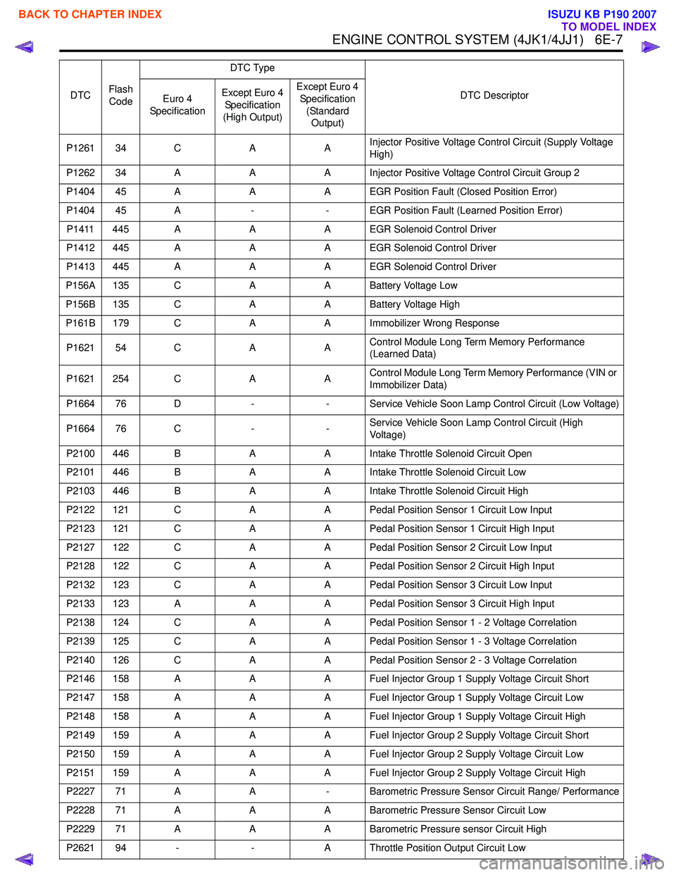
P1261 34 CAAInjector Positive Voltage Control Circuit (Supply Voltage
High)
P1262 34 A AA Injector Positive Voltage Control Circuit Group 2
P1404 45 A AA EGR Position Fault (Closed Position Error)
P1404 45 A -- EGR Position Fault (Learned Position Error)
P1411 445 A AA EGR Solenoid Control Driver
P1412 445 A AA EGR Solenoid Control Driver
P1413 445 A AA EGR Solenoid Control Driver
P156A 135 C AA Battery Voltage Low
P156B 135 C AA Battery Voltage High
P161B 179 C AA Immobilizer Wrong Response
P1621 54 C AAControl Module Long Term Memory Performance
(Learned Data)
P1621 254 C AAControl Module Long Term Memory Performance (VIN or
Immobilizer Data)
P1664 76 D -- Service Vehicle Soon Lamp Control Circuit (Low Voltage)
P1664 76 C --Service Vehicle Soon Lamp Control Circuit (High
Voltage)
P2100 446 B AA Intake Throttle Solenoid Circuit Open
P2101 446 B AA Intake Throttle Solenoid Circuit Low
P2103 446 B AA Intake Throttle Solenoid Circuit High
P2122 121 C AA Pedal Position Sensor 1 Circuit Low Input
P2123 121 C AA Pedal Position Sensor 1 Circuit High Input
P2127 122 C AA Pedal Position Sensor 2 Circuit Low Input
P2128 122 C AA Pedal Position Sensor 2 Circuit High Input
P2132 123 C AA Pedal Position Sensor 3 Circuit Low Input
P2133 123 A AA Pedal Position Sensor 3 Circuit High Input
P2138 124 C AA Pedal Position Sensor 1 - 2 Voltage Correlation
P2139 125 C AA Pedal Position Sensor 1 - 3 Voltage Correlation
P2140 126 C AA Pedal Position Sensor 2 - 3 Voltage Correlation
P2146 158 A AA Fuel Injector Group 1 Supply Voltage Circuit Short
P2147 158 A AA Fuel Injector Group 1 Supply Voltage Circuit Low
P2148 158 A AA Fuel Injector Group 1 Supply Voltage Circuit High
P2149 159 A AA Fuel Injector Group 2 Supply Voltage Circuit Short
P2150 159 A AA Fuel Injector Group 2 Supply Voltage Circuit Low
P2151 159 A AA Fuel Injector Group 2 Supply Voltage Circuit High
P2227 71 A A- Barometric Pressure Sensor Circuit Range/ Performance
P2228 71 A AA Barometric Pressure Sensor Circuit Low
P2229 71 A AA Barometric Pressure sensor Circuit High
P2621 94 - -A Throttle Position Output Circuit Low
DTC
Flash
Code DTC Type
DTC Descriptor
Euro 4
Specification Except Euro 4
Specification
(High Output) Except Euro 4
Specification (Standard Output)
BACK TO CHAPTER INDEX
TO MODEL INDEX
ISUZU KB P190 2007
Page 1661 of 6020
6E-44 ENGINE CONTROL SYSTEM (4JK1/4JJ1)
Diagnostic Starting Point - Engine Controls
Begin the system diagnosis with Diagnostic System
Check - Engine Controls. The Diagnostic System
Check - Engine Controls will provide the following
information:
• The identification of the control modules which command the system.
• The ability of the control modules to communicate through the serial data circuit.
• The identification of any stored diagnostic trouble codes (DTCs) and the their statuses.
The use of the Diagnostic System Check - Engine
Controls will identify the correct procedure for
diagnosing the system and where the procedure is
located.
Important: Engine Control System Check Sheet must
be used to verify the complaint vehicle, you need to
know the correct (normal) operating behavior of the
system and verify that the customer complaint is a valid
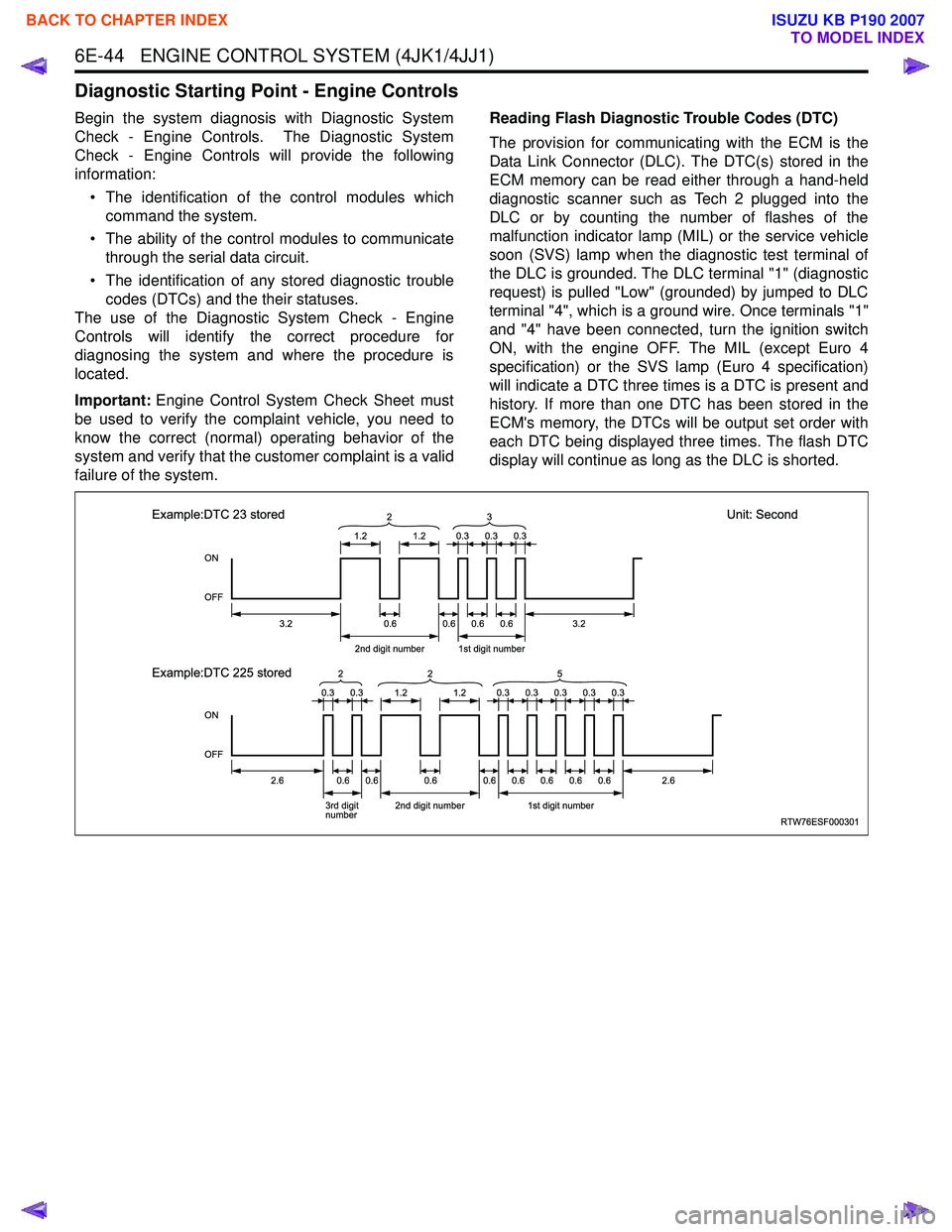
failure of the system. Reading Flash Diagnostic Trouble Codes (DTC)
The provision for communicating with the ECM is the
Data Link Connector (DLC). The DTC(s) stored in the
ECM memory can be read either through a hand-held
diagnostic scanner such as Tech 2 plugged into the
DLC or by counting the number of flashes of the
malfunction indicator lamp (MIL) or the service vehicle
soon (SVS) lamp when the diagnostic test terminal of
the DLC is grounded. The DLC terminal "1" (diagnostic
request) is pulled "Low" (grounded) by jumped to DLC
terminal "4", which is a ground wire. Once terminals "1"
and "4" have been connected, turn the ignition switch
ON, with the engine OFF. The MIL (except Euro 4
specification) or the SVS lamp (Euro 4 specification)
will indicate a DTC three times is a DTC is present and
history. If more than one DTC has been stored in the
ECM's memory, the DTCs will be output set order with
each DTC being displayed three times. The flash DTC
display will continue as long as the DLC is shorted.
RTW76ESF000301
ON
OFF
ON
OFF
1.2
3.2
2.62.6
2nd digit number1st digit number
3.20.6 2
1.2
0.60.60.6
0.30.30.3
0.30.30.30.30.3
Example:DTC 23 stored
Unit: Second
Example:DTC 225 stored
3rd digit
number 2nd digit number1st digit number
0.60.60.60.60.60.60.60.6
3
0.30.31.21.2
2
25
BACK TO CHAPTER INDEX
TO MODEL INDEX
ISUZU KB P190 2007
Page 1662 of 6020
ENGINE CONTROL SYSTEM (4JK1/4JJ1) 6E-45
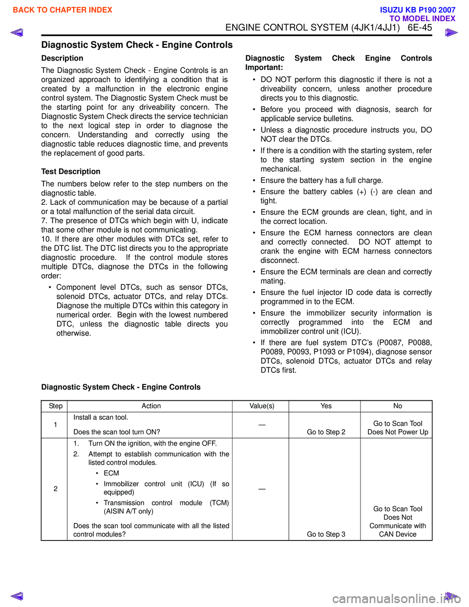
Diagnostic System Check - Engine Controls
Description
The Diagnostic System Check - Engine Controls is an
organized approach to identifying a condition that is
created by a malfunction in the electronic engine
control system. The Diagnostic System Check must be
the starting point for any driveability concern. The
Diagnostic System Check directs the service technician
to the next logical step in order to diagnose the
concern. Understanding and correctly using the
diagnostic table reduces diagnostic time, and prevents
the replacement of good parts.
Test Description
The numbers below refer to the step numbers on the
diagnostic table.
2. Lack of communication may be because of a partial
or a total malfunction of the serial data circuit.
7. The presence of DTCs which begin with U, indicate
that some other module is not communicating.
10. If there are other modules with DTCs set, refer to
the DTC list. The DTC list directs you to the appropriate
diagnostic procedure. If the control module stores
multiple DTCs, diagnose the DTCs in the following
order:
• Component level DTCs, such as sensor DTCs, solenoid DTCs, actuator DTCs, and relay DTCs.
Diagnose the multiple DTCs within this category in
numerical order. Begin with the lowest numbered
DTC, unless the diagnostic table directs you
otherwise. Diagnostic System Check Engine Controls
Important:
• DO NOT perform this diagnostic if there is not a driveability concern, unless another procedure
directs you to this diagnostic.
• Before you proceed with diagnosis, search for applicable service bulletins.
• Unless a diagnostic procedure instructs you, DO NOT clear the DTCs.
• If there is a condition with the starting system, refer to the starting system section in the engine
mechanical.
• Ensure the battery has a full charge.
• Ensure the battery cables (+) (-) are clean and tight.
• Ensure the ECM grounds are clean, tight, and in the correct location.
• Ensure the ECM harness connectors are clean and correctly connected. DO NOT attempt to
crank the engine with ECM harness connectors
disconnect.
• Ensure the ECM terminals are clean and correctly mating.
• Ensure the fuel injector ID code data is correctly programmed in to the ECM.
• Ensure the immobilizer security information is correctly programmed into the ECM and
immobilizer control unit (ICU).
• If there are fuel system DTC’s (P0087, P0088, P0089, P0093, P1093 or P1094), diagnose sensor
DTCs, solenoid DTCs, actuator DTCs and relay
DTCs first.
Diagnostic System Check - Engine Controls
Step Action Value(s)Yes No
1 Install a scan tool.
Does the scan tool turn ON? —
Go to Step 2 Go to Scan Tool
Does Not Power Up
2 1. Turn ON the ignition, with the engine OFF.
2. Attempt to establish communication with the listed control modules.
•ECM
• Immobilizer control unit (ICU) (If so equipped)
• Transmission control module (TCM) (AISIN A/T only)
Does the scan tool communicate with all the listed
control modules? —
Go to Step 3 Go to Scan Tool
Does Not
Communicate with CAN Device
BACK TO CHAPTER INDEX
TO MODEL INDEX
ISUZU KB P190 2007
Page 1664 of 6020
ENGINE CONTROL SYSTEM (4JK1/4JJ1) 6E-47
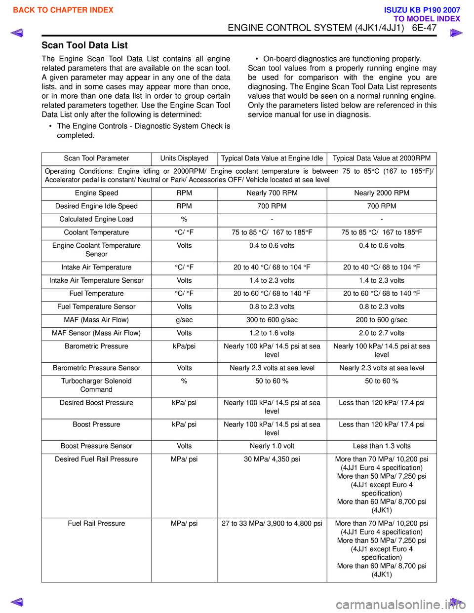
Scan Tool Data List
The Engine Scan Tool Data List contains all engine
related parameters that are available on the scan tool.
A given parameter may appear in any one of the data
lists, and in some cases may appear more than once,
or in more than one data list in order to group certain
related parameters together. Use the Engine Scan Tool
Data List only after the following is determined:
• The Engine Controls - Diagnostic System Check is completed. • On-board diagnostics are functioning properly.
Scan tool values from a properly running engine may
be used for comparison with the engine you are
diagnosing. The Engine Scan Tool Data List represents
values that would be seen on a normal running engine.
Only the parameters listed below are referenced in this
service manual for use in diagnosis.
Scan Tool Parameter Units Displayed Typical Data Value at Engine Idle Typical Data Value at 2000RPM
Operating Conditions: Engine idling or 2000RPM/ Engine coolant temperature is between 75 to 85 °C (167 to 185 °F)/
Accelerator pedal is constant/ Neutral or Park/ Accessories OFF/ Vehicle located at sea level
Engine Speed RPMNearly 700 RPM Nearly 2000 RPM
Desired Engine Idle Speed RPM700 RPM 700 RPM
Calculated Engine Load %- -
Coolant Temperature °C/ °F 75 to 85 °C/ 167 to 185 °F 75 to 85 °C/ 167 to 185 °F
Engine Coolant Temperature Sensor Volts
0.4 to 0.6 volts 0.4 to 0.6 volts
Intake Air Temperature °C/ °F 20 to 40 °C/ 68 to 104 °F 20 to 40 °C/ 68 to 104 °F
Intake Air Temperature Sensor Volts 1.4 to 2.3 volts1.4 to 2.3 volts
Fuel Temperature °C/ °F 20 to 60 °C/ 68 to 140 °F 20 to 60 °C/ 68 to 140 °F
Fuel Temperature Sensor Volts0.8 to 2.3 volts 0.8 to 2.3 volts
MAF (Mass Air Flow) g/sec300 to 600 g/sec 200 to 600 g/sec
MAF Sensor (Mass Air Flow) Volts1.2 to 1.6 volts 2.0 to 2.7 volts
Barometric Pressure kPa/psi Nearly 100 kPa/ 14.5 psi at sea
levelNearly 100 kPa/ 14.5 psi at sea
level
Barometric Pressure Sensor VoltsNearly 2.3 volts at sea level Nearly 2.3 volts at sea level
Turbocharger Solenoid Command %
50 to 60 % 50 to 60 %
Desired Boost Pressure kPa/ psi Nearly 100 kPa/ 14.5 psi at sea
levelLess than 120 kPa/ 17.4 psi
Boost Pressure kPa/ psi Nearly 100 kPa/ 14.5 psi at sea
levelLess than 120 kPa/ 17.4 psi
Boost Pressure Sensor VoltsNearly 1.0 volt Less than 1.3 volts
Desired Fuel Rail Pressure MPa/ psi 30 MPa/ 4,350 psiMore than 70 MPa/ 10,200 psi
(4JJ1 Euro 4 specification)
More than 50 MPa/ 7,250 psi
(4JJ1 except Euro 4 specification)
More than 60 MPa/ 8,700 psi
(4JK1)
Fuel Rail Pressure MPa/ psi 27 to 33 MPa/ 3,900 to 4,800 psi More than 70 MPa/ 10,200 psi
(4JJ1 Euro 4 specification)
More than 50 MPa/ 7,250 psi (4JJ1 except Euro 4 specification)
More than 60 MPa/ 8,700 psi (4JK1)
BACK TO CHAPTER INDEX
TO MODEL INDEX
ISUZU KB P190 2007
Page 1666 of 6020
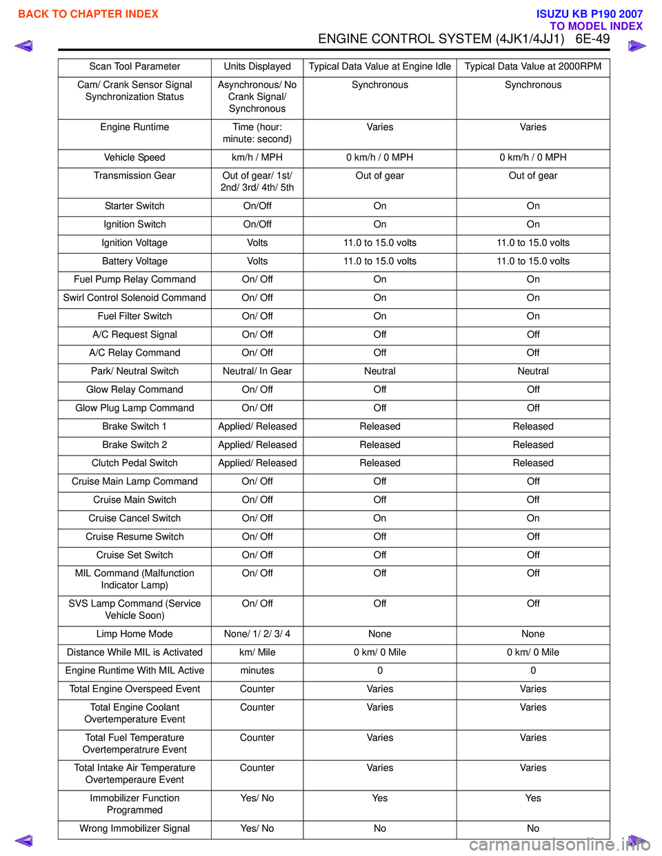
ENGINE CONTROL SYSTEM (4JK1/4JJ1) 6E-49
Cam/ Crank Sensor Signal Synchronization Status Asynchronous/ No
Crank Signal/ Synchronous Synchronous Synchronous
Engine Runtime Time (hour: minute: second) Va r i e s
Va r i e s
Vehicle Speed km/h / MPH0 km/h / 0 MPH 0 km/h / 0 MPH
Transmission Gear Out of gear/ 1st/ 2nd/ 3rd/ 4th/ 5th Out of gear
Out of gear
Starter Switch On/OffOn On
Ignition Switch On/OffOn On
Ignition Voltage Volts11.0 to 15.0 volts 11.0 to 15.0 volts
Battery Voltage Volts11.0 to 15.0 volts 11.0 to 15.0 volts
Fuel Pump Relay Command On/ Off OnOn
Swirl Control Solenoid Command On/ Off OnOn
Fuel Filter Switch On/ OffOn On
A/C Request Signal On/ OffOff Off
A/C Relay Command On/ OffOff Off
Park/ Neutral Switch Neutral/ In Gear NeutralNeutral
Glow Relay Command On/ OffOff Off
Glow Plug Lamp Command On/ Off OffOff
Brake Switch 1 Applied/ Released Released Released
Brake Switch 2 Applied/ Released Released Released
Clutch Pedal Switch Applied/ Released ReleasedReleased
Cruise Main Lamp Command On/ Off OffOff
Cruise Main Switch On/ OffOff Off
Cruise Cancel Switch On/ OffOn On
Cruise Resume Switch On/ OffOff Off
Cruise Set Switch On/ OffOff Off
MIL Command (Malfunction Indicator Lamp) On/ Off
Off Off
SVS Lamp Command (Service Vehicle Soon) On/ Off
Off Off
Limp Home Mode None/ 1/ 2/ 3/ 4 None None
Distance While MIL is Activated km/ Mile 0 km/ 0 Mile0 km/ 0 Mile
Engine Runtime With MIL Active minutes 00
Total Engine Overspeed Event Counter VariesVaries
Total Engine Coolant
Overtemperature Event Counter
Varies Varies
Total Fuel Temperature
Overtemperatrure Event Counter
Varies Varies
Total Intake Air Temperature Overtemperaure Event Counter
Varies Varies
Immobilizer Function Programmed Ye s / N o
Ye s Ye s
Wrong Immobilizer Signal Yes/ NoNo No
Scan Tool Parameter Units Displayed Typical Data Value at Engine Idle Typical Data Value at 2000RPM
BACK TO CHAPTER INDEX
TO MODEL INDEX
ISUZU KB P190 2007