2007 ISUZU KB P190 service
[x] Cancel search: servicePage 1972 of 6020
ENGINE CONTROL SYSTEM (4JK1/4JJ1) 6E-355
Electrostatic Discharge Damage
Electronic components used in the ECM are often
designed to carry very low voltage. Electronic
components are susceptible to damage caused by
electrostatic discharge. By comparison, as much as
4,000 volts may be needed for a person to feel even
the zap of a static discharge. There are several ways
for a person to become statically charged. The most
common methods of charging are by friction and
induction.
• An example of charging by friction is a person sliding across a vehicle seat.
Important: To prevent possible electrostatic discharge
damage, follow these guidelines:
• Do not touch the ECM connector pins or soldered components on the ECM circuit board.
• Do not open the replacement part package until the part is ready to be installed.
• Before removing the part from the package, ground the package to a known good ground on
the vehicle.
• If the part has been handled while sliding across the seat, while sitting down from a standing
position, or while walking a distance, touch a
known good ground before installing the part.
• Charge by induction occurs when a person with well insulated shoes stands near a highly charged
object and momentarily touches ground. Charges
of the same polarity are drained off leaving the
person highly charged with opposite polarity.
Malfunction Indicator Lamp (MIL) Operation
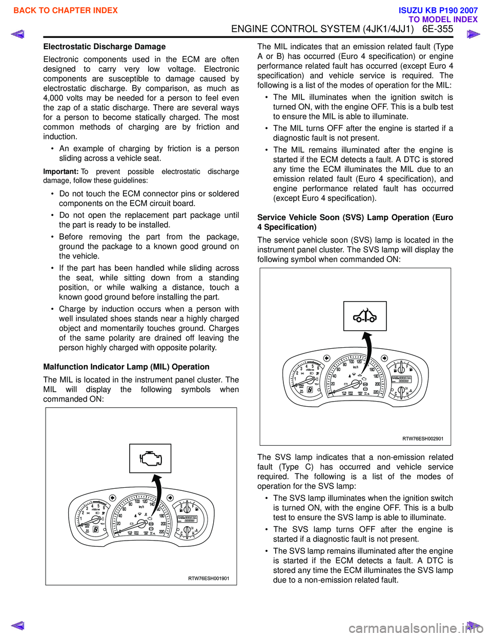
The MIL is located in the instrument panel cluster. The
MIL will display the following symbols when
commanded ON: The MIL indicates that an emission related fault (Type
A or B) has occurred (Euro 4 specification) or engine
performance related fault has occurred (except Euro 4
specification) and vehicle service is required. The
following is a list of the modes of operation for the MIL:
• The MIL illuminates when the ignition switch is turned ON, with the engine OFF. This is a bulb test
to ensure the MIL is able to illuminate.
• The MIL turns OFF after the engine is started if a diagnostic fault is not present.
• The MIL remains illuminated after the engine is started if the ECM detects a fault. A DTC is stored
any time the ECM illuminates the MIL due to an
emission related fault (Euro 4 specification), and
engine performance related fault has occurred
(except Euro 4 specification).
Service Vehicle Soon (SVS) Lamp Operation (Euro
4 Specification)
The service vehicle soon (SVS) lamp is located in the
instrument panel cluster. The SVS lamp will display the
following symbol when commanded ON:
The SVS lamp indicates that a non-emission related
fault (Type C) has occurred and vehicle service
required. The following is a list of the modes of
operation for the SVS lamp:
• The SVS lamp illuminates when the ignition switch is turned ON, with the engine OFF. This is a bulb
test to ensure the SVS lamp is able to illuminate.
• The SVS lamp turns OFF after the engine is started if a diagnostic fault is not present.
• The SVS lamp remains illuminated after the engine is started if the ECM detects a fault. A DTC is
stored any time the ECM illuminates the SVS lamp
due to a non-emission related fault.
RTW76ESH001901
RTW76ESH002901
BACK TO CHAPTER INDEX
TO MODEL INDEX
ISUZU KB P190 2007
Page 2017 of 6020
ENGINE MECHANICAL (C24SE) 6A-3
PAGE
ENGINE EXTERNAL PARTS ........................................................................................... 6A-65 Radiator ....................................................................................................................... 6A-65
Thermostat .................................................................................................................. 6A -66
Water Pump ................................................................................................................. 6A- 66
Coating sealing surfaces with Silicone Grease ....................................................... 6A-67
Alternator ..................................................................................................................... 6A-67
Starter ........................................................................................................................ .. 6A-67
V-belt Tension of Alternator ....................................................................................... 6A-68
FUEL INJECTION SYSTEM ............................................................................................. 6A-70 Map Sensor ................................................................................................................. 6A- 70
Pressure Regulator..................................................................................................... 6A-70
ECM (Engine Control Module) ................................................................................... 6A-70
ECT............................................................................................................................ ... 6A-71
Idle Air Control(IAC) Valve ......................................................................................... 6A-71
Ignition Coil ................................................................................................................. 6A-71
Crank Position Sensor ............................................................................................... 6A-72
FUEL INJECTOR .............................................................................................................. 6A- 73
Knock Sensor.............................................................................................................. 6A-7 3
Oxygen Sensor............................................................................................................ 6A-74
Throttle Valve Position Sensor .................................................................................. 6A-74
Acclelerator Pedal and Cable .................................................................................... 6A-74
Air Cleaner Filter ......................................................................................................... 6A- 75
Spark Plug Thread ...................................................................................................... 6A-76
TECHNICAL DATA ........................................................................................................... 6A-77
Recommended Troque Values .................................................................................. 6A-88
SPECIAL SERVICE TOOL ............................................................................................... 6A-89
BACK TO CHAPTER INDEX
TO MODEL INDEX
ISUZU KB P190 2007
Page 2018 of 6020
6A-4 ENGINE MECHANICAL (C24SE)
GENERAL DESCRIPTION
Engine Cleanliness And Care
An automobile engine is a combination of many machined, honed, polished and lapped surfaces with tolerances
that are measured in the thousandths of a millimeter (ten thousandths of an inch). Accordingly, when any internal
engine parts are serviced, care and cleanliness are important. Throughout this section, it should be understood that
proper cleaning and protection of machined surfaces and friction areas is part of the repair procedure. This is
considered standard shop practice even if not specifically stated.
�z A liberal coating of engine oil should be applied to all friction areas during assembly to protect and lubricate
the surfaces on initial operation.
�z W henever valve train components, pistons, piston rings, connecting rods, rod bearings, and crankshaft journal
bearings are removed for service, they should be retained in order.
�z
At the time of installation, they should be installed in the same locations and with the same mating surfaced as
when removed.
�z Battery cables should be disconnected before any major work is performed on the engine. Failure to
disconnect cables may result in damage to wire harness or other electrical parts.
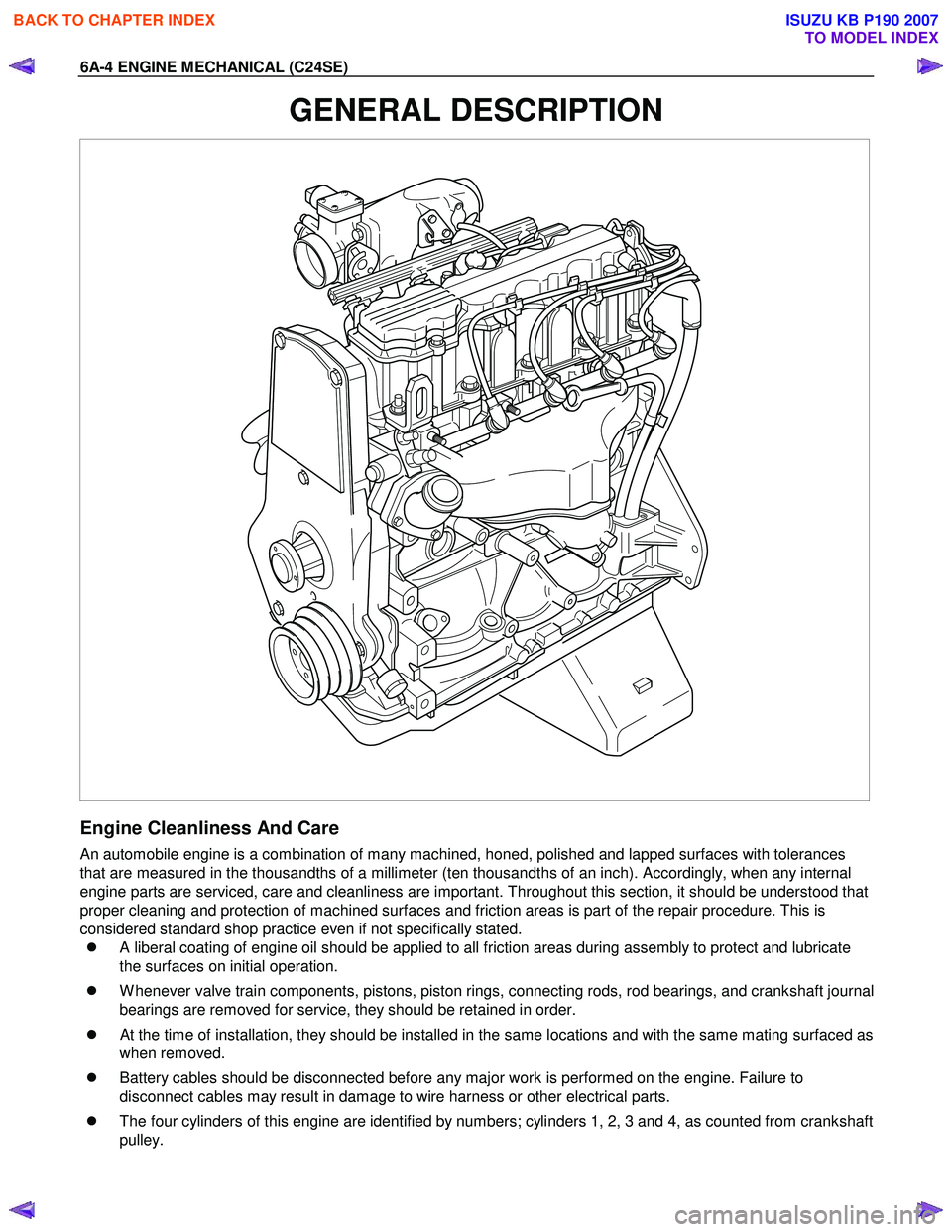
�z The four cylinders of this engine are identified by numbers; cylinders 1, 2, 3 and 4, as counted from crankshaft
pulley.
BACK TO CHAPTER INDEX
TO MODEL INDEX
ISUZU KB P190 2007
Page 2019 of 6020
ENGINE MECHANICAL (C24SE) 6A-5
General Information on Engine Service
The following information on engine service should be noted carefully, as it is important in preventing damage and
contributing to reliable engine performance:
�z W hen raising or supporting the engine for any reason, do not use a jack under the oil pan. Due to the small
clearance between the oil pan and the oil pump strainer, jacking against the oil pan may cause damage to the
oil pick up unit.
�z The 12-volt electrical system is capable of damaging circuits. W hen performing any work where electrical
terminals could possible be grounded, the ground cable of the battery should be disconnected at the battery.
�z Any time the intake air duct or air cleaner is removed, the intake opening should be covered. This will protect
against accidental entrance of foreign material into the cylinder which could cause extensive damage when
the engine is started.
Cylinder Block
The cylinder block is made of cast iron. The crankshaft is supported by five bearings. The bearing cap is made of
nodular cast iron.
Cylinder Head
The cylinder head is made of aluminum alloy casting with a spark plug in the center.
Valve Train
Valve system is a single over head camshaft.
The valves clearance adjustment are hydraulic.
Hydraulic valve lifter adjustment, no adjustment necessary.
Intake Manifold
The intake manifold is made of aluminum alloy.
Exhaust Manifold
The exhaust manifold is made of high Si-Mo nodular iron.
Pistons and Connecting Rods
Aluminum pistons are used after selecting the grade that meets the cylinder bore diameter. Each piston has two
compression rings and one oil ring. The piston pin is made of cast hardened steel. The connecting rod bearings are
made of modular cast iron. The connecting rod bearings are made of steel backed with tri-metal babbitt metal.
Crankshaft and Bearings
The crank shaft is made of modular cast iron. Pins and journal are graded for correct size selection for their bearing.
BACK TO CHAPTER INDEX
TO MODEL INDEX
ISUZU KB P190 2007
Page 2027 of 6020

ENGINE MECHANICAL (C24SE) 6A-13
Valve System C24SE
Actuation Type Direct-acting Inverted Bucked Tappet
Valve Clearance Adjustment Hydraulic
Valve Rotor Type None
Inlet-Valve Material Chromium Alloyed Steel
-Seat Insert MaterialSintered Iron
Exhaust-Valve Material Head: Cr-Mn-Ni Alloyed Shaft: Cr-Si Alloyed &Cr plated
-Seat Insert MaterialSintered Iron
Valve Spring Material GME 06 100-C1
Valve Guide Material QS 13 MR 00
Valve Seal Type Lip
Water Pump C24SE
Type Centrifugal
Drive-Material &Type HNBR Toothed-belt
Bearing Type Double Row Ball
Shaft Seal Type Mechanical Ceramic
Thermostat-Coolant C24SE
Type Bypass
Oil Pump & Filter C24SE
Type Gear Pump
Location Front of Engine
Drive Direct Crankshaft Driven
Filter Type Full Flow with Bypass for blocked filter
Oil & Oil Reservoir C24SE
Reservoir-Description & Location 1-piece below Engine
Reservoir Material Aluminum Alloy (pressure cast)
Replacement Oil Fill Volume
-W ith Filter change4.25liters
-W ithout Filter change 4.00liters
Recommended Oil-Run-in 10W /30SG
-Service (above-18°C) 10W /40SG
-Service (below-18°C) 5W /30SG
Oil Classification API&CCMC
Ignition Components C24SE
Spark Plugs Conventional
Type Electronic Spark Control
No. of Coils &Type 2 Solid State
Coil Location Engine-mounted
Ignition Lead Type Inductive (hi-resistance)
BACK TO CHAPTER INDEX
TO MODEL INDEX
ISUZU KB P190 2007
Page 2058 of 6020
6A-44 ENGINE MECHANICAL (C24SE)
Valve, Grind
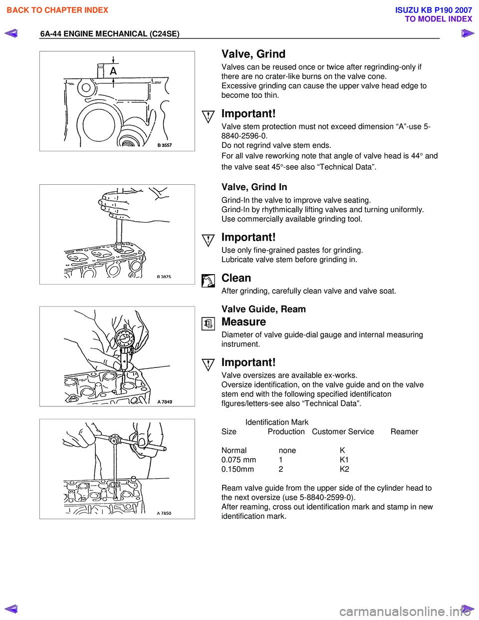
Valves can be reused once or twice after regrinding-only if
there are no crater-like burns on the valve cone.
Excessive grinding can cause the upper valve head edge to
become too thin.
Important!
Valve stem protection must not exceed dimension “A”-use 5-
8840-2596-0.
Do not regrind valve stem ends.
For all valve reworking note that angle of valve head is 44 °and
the valve seat 45 °-see also “Technical Data”.
Valve, Grind In
Grind-In the valve to improve valve seating.
Grind-In by rhythmically lifting valves and turning uniformly.
Use commercially available grinding tool.
Important!
Use only fine-grained pastes for grinding.
Lubricate valve stem before grinding in.
Clean
After grinding, carefully clean valve and valve soat.
Valve Guide, Ream
Measure
Diameter of valve guide-dial gauge and internal measuring
instrument.
Important!
Valve oversizes are available ex-works.
Oversize identification, on the valve guide and on the valve
stem end with the following specified identificaton
flgures/letters-see also “Technical Data”.
Identification Mark
Size Production Customer Service Reamer
Normal none K
0.075 mm 1 K1
0.150mm 2 K2
Ream valve guide from the upper side of the cylinder head to
the next oversize (use 5-8840-2599-0).
After reaming, cross out identification mark and stamp in new
identification mark.
BACK TO CHAPTER INDEX
TO MODEL INDEX
ISUZU KB P190 2007
Page 2072 of 6020
6A-58 ENGINE MECHANICAL (C24SE)
Clean
Plastigage from journals.
Lightly coat journals and bearings with engine oil.
Installation
Install bearing cap and shell using new bolts.
Torque - Angle Method
Main bearing cap bolt - 60 N ⋅m (6.1 kgf ⋅m) +40 ° to 50 °.
Con-rod bearing cap bolts - 35 N ⋅m (3.9 kgf ⋅m) +45 °.
2.Micrometer and gauge method.
Crankshaft removed.
Installation
1. Install caps and bearing shells to con-rods and cylinder block.
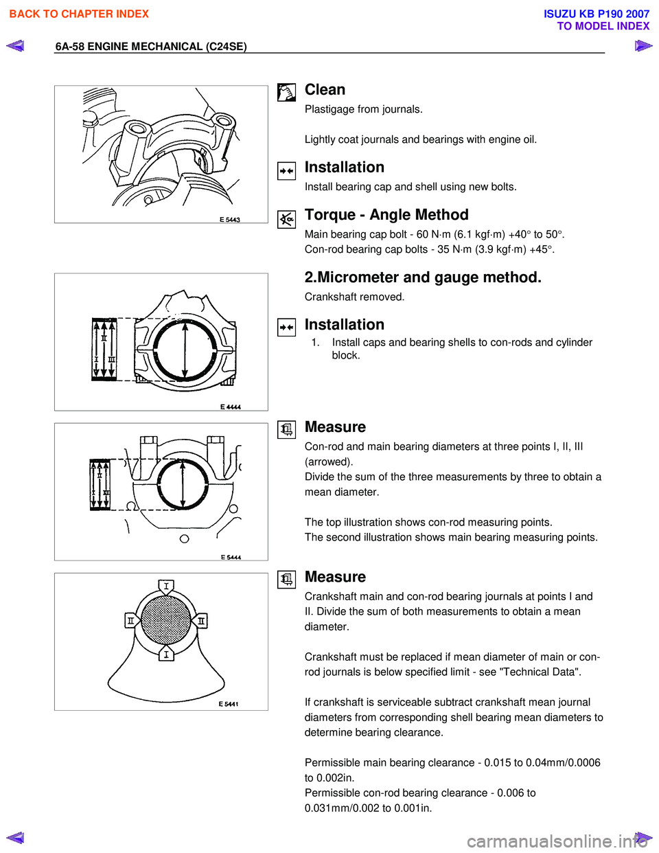
Measure
Con-rod and main bearing diameters at three points I, II, III
(arrowed).
Divide the sum of the three measurements by three to obtain a
mean diameter.
The top illustration shows con-rod measuring points.
The second illustration shows main bearing measuring points.
Measure
Crankshaft main and con-rod bearing journals at points I and
II. Divide the sum of both measurements to obtain a mean
diameter.
Crankshaft must be replaced if mean diameter of main or con-
rod journals is below specified limit - see "Technical Data".
If crankshaft is serviceable subtract crankshaft mean journal
diameters from corresponding shell bearing mean diameters to
determine bearing clearance.
Permissible main bearing clearance - 0.015 to 0.04mm/0.0006
to 0.002in.
Permissible con-rod bearing clearance - 0.006 to
0.031mm/0.002 to 0.001in.
BACK TO CHAPTER INDEX
TO MODEL INDEX
ISUZU KB P190 2007
Page 2094 of 6020
6A-80 ENGINE MECHANICAL (C24SE)
Cylinder Head (continued)
Valve System
Valve lifter valve play compensator
(hydraulic)
Valve rotators
(inlet or outlet) outlet
Valve play
(warm or cold) inlet mm 0
outlet mm 0
Cylinder head bottom, face parallelism mm 0.05
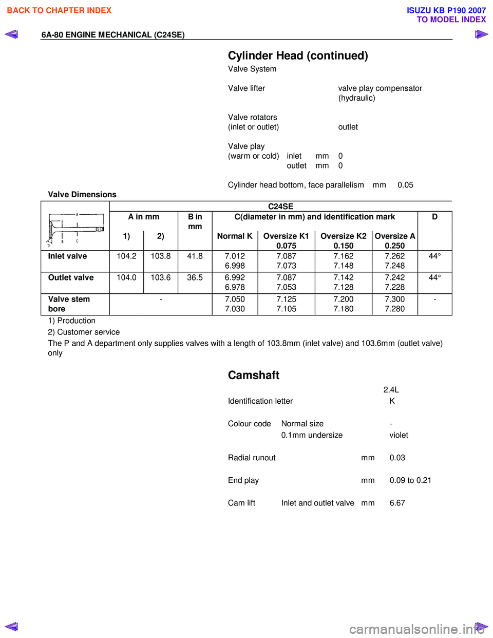
Valve Dimensions
C24SE
A in mm B in
mm C(diameter in mm) and identification mark D
1) 2) Normal K Oversize K1
0.075 Oversize K2
0.150 Oversize A
0.250
Inlet valve
104.2 103.8 41.8 7.012
6.998 7.087
7.073 7.162
7.148 7.262
7.248 44
°
Outlet valve 104.0 103.6 36.5 6.992
6.978 7.087
7.053 7.142
7.128 7.242
7.228 44
°
Valve stem
bore - 7.050
7.030 7.125
7.105 7.200
7.180 7.300
7.280 -
1) Production
2) Customer service
The P and A department only supplies valves with a length of 103.8mm (inlet valve) and 103.6mm (outlet valve)
only
Camshaft
2.4L
Identification letter K
Colour code Normal size -
0.1mm undersize violet
Radial runout mm 0.03
End play mm 0.09 to 0.21
Cam lift Inlet and outlet valve mm 6.67
BACK TO CHAPTER INDEX
TO MODEL INDEX
ISUZU KB P190 2007