2007 ISUZU KB P190 service
[x] Cancel search: servicePage 2096 of 6020
6A-82 ENGINE MECHANICAL (C24SE)
Crankshaft, Cylinder Block
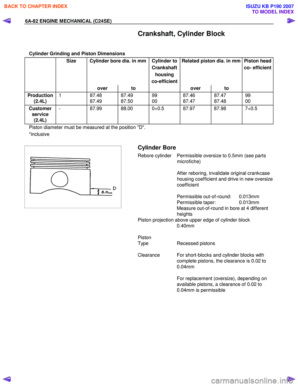
Cylinder Grinding and Piston Dimensions
Size Cylinder bore dia. in mm Cylinder to Related piston dia. in mm Piston head
Crankshaft co- efficient
housing
co-efficient
over to over to
Production
(2.4L) 1 87.48
87.49 87.49
87.50 99
00 87.46
87.47 87.47
87.48 99
00
Customer service (2.4L) - 87.99 88.00 0+0.5 87.97 87.98 7+0.5
Piston diameter must be measured at the position "D".
*inclusive
Cylinder Bore
Rebore cylinder Permissible oversize to 0.5mm (see parts
microfiche)
After reboring, invalidate original crankcase
housing coefficient and drive in new oversize
coefficient
Permissible out-of-round: 0.013mm
Permissible taper: 0.013mm
Measure out-of-round in bore at 4 different
heights
Piston projection above upper edge of cylinder block 0.40mm
Piston
Type Recessed pistons
Clearance For short-blocks and cylinder blocks with complete pistons, the clearance is 0.02 to
0.04mm
For replacement (oversize), depending on
available pistons, a clearance of 0.02 to
0.04mm is permissible
BACK TO CHAPTER INDEX
TO MODEL INDEX
ISUZU KB P190 2007
Page 2098 of 6020
6A-84 ENGINE MECHANICAL (C24SE)
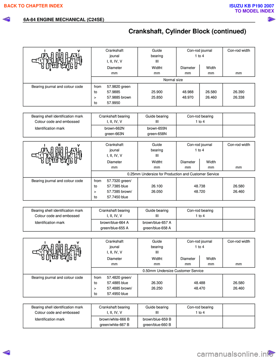
Crankshaft, Cylinder Block (continued)
Crankshaft jounal
I, II, IV, V Guide
bearing III Con-rod journal
1 to 4 Con-rod width
Diameter
mm Widtht
mm Diameter
mm Width
mm
mm
Normal size
Bearing journal and colour code from 57.9820 green
to 57.9885
> 57.9885 brown
to 57.9950
25.900
25.850
48.988
48.970
26.580
26.460
26.390
26.338
Bearing shell identification mark
Colour code and embossed Crankshaft bearing
I, II, IV, V Guide bearing
III Con-rod bearing
1 to 4
Identification mark
brown-662N
green-663N brown-655N
green-658N
Crankshaft
jounal
I, II, IV, V Guide
bearing III Con-rod journal
1 to 4 Con-rod width
Diameter
mm Widtht
mm Diameter
mm Width
mm
mm
0.25mm Undersize for Production and Customer Service
Bearing journal and colour code from 57.7320 green/
to 57.7385 blue
> 57.7385 brown/
to 57.7450 blue
26.100
26.050
48.738
48.720
26.580
26.460
Bearing shell identification mark Colour code and embossed Crankshaft bearing
I, II, IV, V Guide bearing
III Con-rod bearing
1 to 4
Identification mark
brown/blue-664 A
green/blue-655 A brown/blue-657 A
green/blue-658 A
Crankshaft jounal
I, II, IV, V Guide
bearing III Con-rod journal
1 to 4 Con-rod width
Diameter
mm Widtht
mm Diameter
mm Width
mm
mm
0.50mm Undersize Customer Service
Bearing journal and colour code from 57.4820 green/
to 57.4885 blue
> 57.4885 brown/
to 57.4950 blue
26.300
26.250
48.488
48.470
26.580
26.460
Bearing shell identification mark
Colour code and embossed Crankshaft bearing
I, II, IV, V Guide bearing
III Con-rod bearing
1 to 4
Identification mark
brown/white-666 B
green/white-667 B brown/blue-659 B
green/blue-660 B
BACK TO CHAPTER INDEX
TO MODEL INDEX
ISUZU KB P190 2007
Page 2100 of 6020
6A-86 ENGINE MECHANICAL (C24SE)
Con-rod
Permissible, weight variation of con-rods without pistons and bearing shells within an engine 8 g.
As the con-rods have no counterweights, re-working is not possible.
Con-rods must be replaced only as a set.
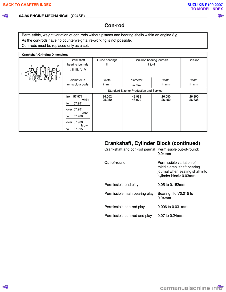
Crankshaft Grinding Dimensions
Crankshaft
bearing journals
I, II, III, IV, V Guide bearings
III
Con-Rod bearing journals
1 to 4
Con-rod
diameter
in
mm/colour code width
in mm diameter
in mm width
in mm width
in mm
Standard Size for Production and Service
from 57.974
white
to 57.981
over 57.981 green
to 57.988
over 57.988 brown
to 57.995 26.002
25.950
48.988
48.970
26.580
26.450
26.390
26.338
Crankshaft, Cylinder Block (continued)
Crankshaft and con-rod journal Permissible out-of-round:
0.04mm
Out-of-round Permissible variation of
middle crankshaft bearing
journal when seating shaft into
cylinder block: 0.03mm
Permissible end play 0.05 to 0.152mm
Permissible main bearing play Bearing I to V0.015 to 0.04mm
Permissible con-rod play 0.006 to 0.031mm
Permissible con-rod and play 0.07 to 0.24mm
BACK TO CHAPTER INDEX
TO MODEL INDEX
ISUZU KB P190 2007
Page 2103 of 6020
ENGINE MECHANICAL (C24SE) 6A-89
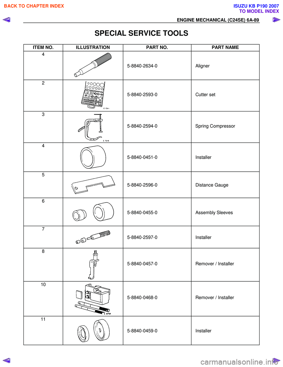
SPECIAL SERVICE TOOLS
ITEM NO. ILLUSTRATION PART NO. PART NAME
4
5-8840-2634-0
Aligner
2
5-8840-2593-0
Cutter set
3
5-8840-2594-0
Spring Compressor
4
5-8840-0451-0
Installer
5
5-8840-2596-0
Distance Gauge
6
5-8840-0455-0
Assembly Sleeves
7
5-8840-2597-0
Installer
8
5-8840-0457-0
Remover / Installer
10
5-8840-0468-0
Remover / Installer
11
5-8840-0459-0
Installer
BACK TO CHAPTER INDEX
TO MODEL INDEX
ISUZU KB P190 2007
Page 2105 of 6020
ENGINE COOLING 6B-1
SECTION 6B
ENGINE COOLING
TABLE OF CONTENTS
PAGE
General Description ....................................................................................................... 6B- 2
Service Precaution ......................................................................................................... 6B- 3
Diagnosis ...................................................................................................................... .. 6B- 5
Draining and Refilling Cooling System ........................................................................ 6B- 6
Water Pump .................................................................................................................... 6B- 7
Water Pump and Associated Parts .......................................................................... 6B- 7
Removal ...................................................................................................................... 6 B- 7
Inspection ................................................................................................................... 6 B- 7
Installation .................................................................................................................. 6B- 8
Thermostat ..................................................................................................................... . 6B- 9
Removal ...................................................................................................................... 6 B- 9
Inspection ................................................................................................................... 6 B- 9
Installation .................................................................................................................. 6B- 9
Fan clutch with Cooling Fan.......................................................................................... 6B- 9 Inspection and Repair ............................................................................................... 6B- 9
Radiator ....................................................................................................................... .... 6B-11
Radiator and Associated Parts ................................................................................. 6B-11
Removal ...................................................................................................................... 6 B-11
Inspection ................................................................................................................... 6 B-12
Installation .................................................................................................................. 6B-13
Main Data and Specifications ........................................................................................ 6B-13
Special Service Tool....................................................................................................... 6B- 14
BACK TO CHAPTER INDEX
TO MODEL INDEX
ISUZU KB P190 2007
Page 2107 of 6020
ENGINE COOLING 6B-3
Service Precaution
CAUTION:
Always use the correct fastener in the proper location.
When you replace a fastener, use ONLY the exact part
number for that application. ISUZU will call out those
fasteners that require a replacement after removal. ISUZU
will also call out the fasteners that require thread lockers
or thread sealant. UNLESS OTHERWISE SPECIFIED, do
not use supplemental coatings (Paints, greases, or other
corrosion inhibitors) on threaded fasteners or fastener
joint interfaces. Generally, such coatings adversely affect
the fastener torque and the joint clamping force, and may
damage the fastener. When you install fasteners, use the
correct tightening sequence and specifications. Following
these instructions can help you avoid damage to parts
and systems.
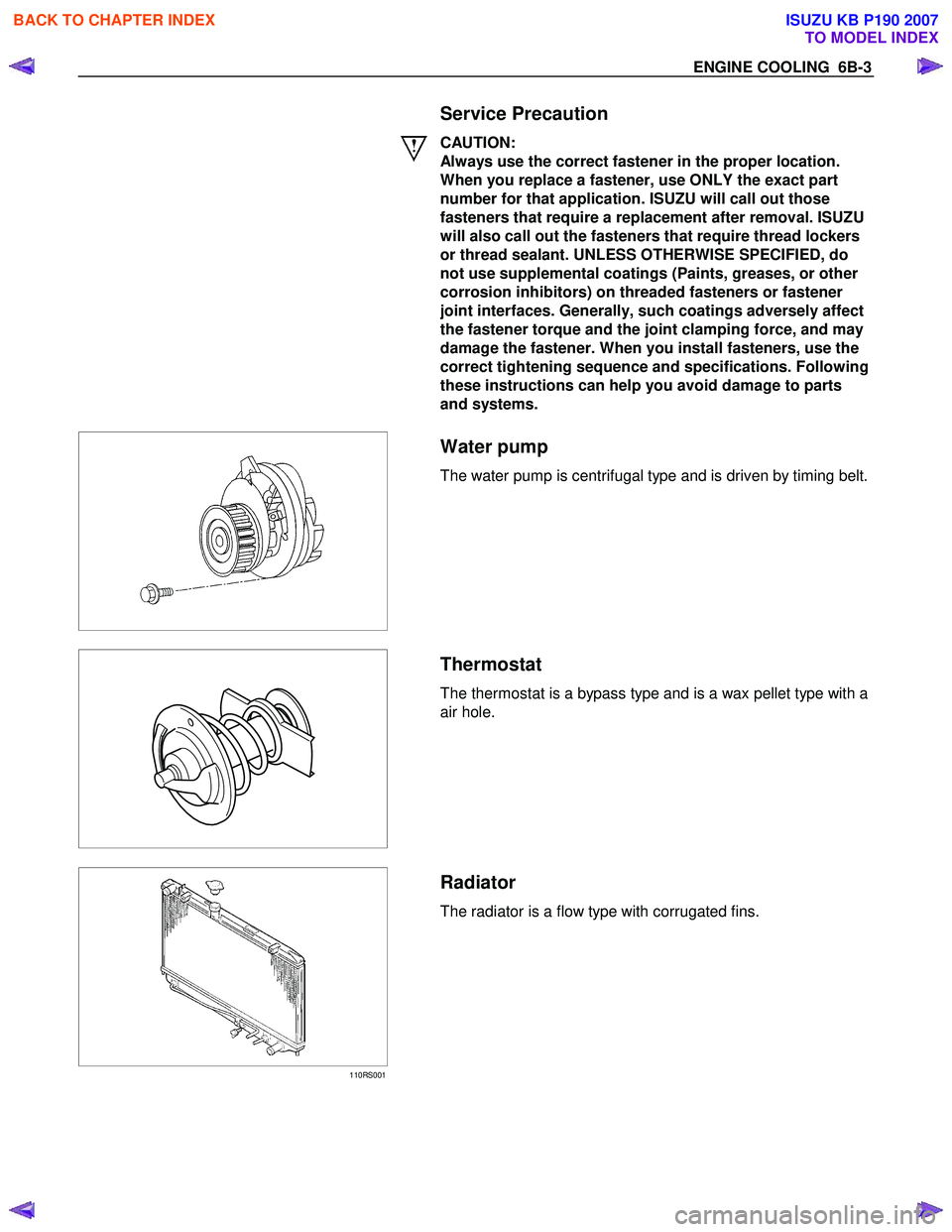
Water pump
The water pump is centrifugal type and is driven by timing belt.
Thermostat
The thermostat is a bypass type and is a wax pellet type with a
air hole.
110RS001
Radiator
The radiator is a flow type with corrugated fins.
BACK TO CHAPTER INDEX
TO MODEL INDEX
ISUZU KB P190 2007
Page 2110 of 6020
6B-6 ENGINE COOLING
Draining and Refilling Cooling
System
Before draining the cooling system, inspect the system and
perform any necessary service to ensure that it is clean, does
not leak and is in proper working order. The engine coolant
level should be between the "MIN" and "MAX" lines of reserve
tank when the engine is cold. If low, check for leakage and add
engine coolant up to the "MAX" line. There should not be any
excessive deposit of rust or scales around the radiator cap or
radiator filler hole, and the engine coolant should also be free
from oil.
Replace the engine coolant if excessively dirty.
1. Completely drain the cooling system by opening the drain
plug at the bottom of the radiator.
2. Remove the radiator cap.
WARNING: TO AVOID THE DANGER OF BEING BURNED,
DO NOT REMOVE THE CAP WHILE THE ENGINE AND
RADIATOR ARE STILL HOT. SCALDING FLUID AND
STEAM CAN BE BLOWN OUT UNDER PRESSURE.
3. Disconnect all hoses from the engine coolant reserve tank.
Scrub and clean the inside of the reserve tank with soap and water. Flush it well with clean water, then drain it. Install
the reserve tank and hoses.
4. Refill the cooling system with the engine coolant using a solution that is at least 50 percent antifreeze.
5. Fill the radiator to the base of the filler neck.
Fill the engine coolant reserve tank to "MAX" line when the engine is cold.
6. Block the drive wheels and firmly apply the parking brake and place the shift lever in the "NEUTRAL" position.
7. Remove the radiator cap. Start the engine and warm it up at 2,500 - 3,000 rpm for about 30 minutes.
8. W hen the air comes out from the radiator filler neck and the engine coolant level has gone down, replenish with the
engine coolant. Repeat this procedure until the engine
coolant level does not go down. Then stop the engine and
install the radiator cap. Let the engine cool down.
9. After the engine has cooled, replenish with engine coolant up to the "MAX" line of the reserve tank.
10. Start the engine. W ith the engine running at 3,000 rpm, make sure there is no running water sound from the heate
r
core (behind the center console).
11. If the running water sound is heard, repeat steps 8 to 10.
BACK TO CHAPTER INDEX
TO MODEL INDEX
ISUZU KB P190 2007
Page 2118 of 6020
6B-14 ENGINE COOLING
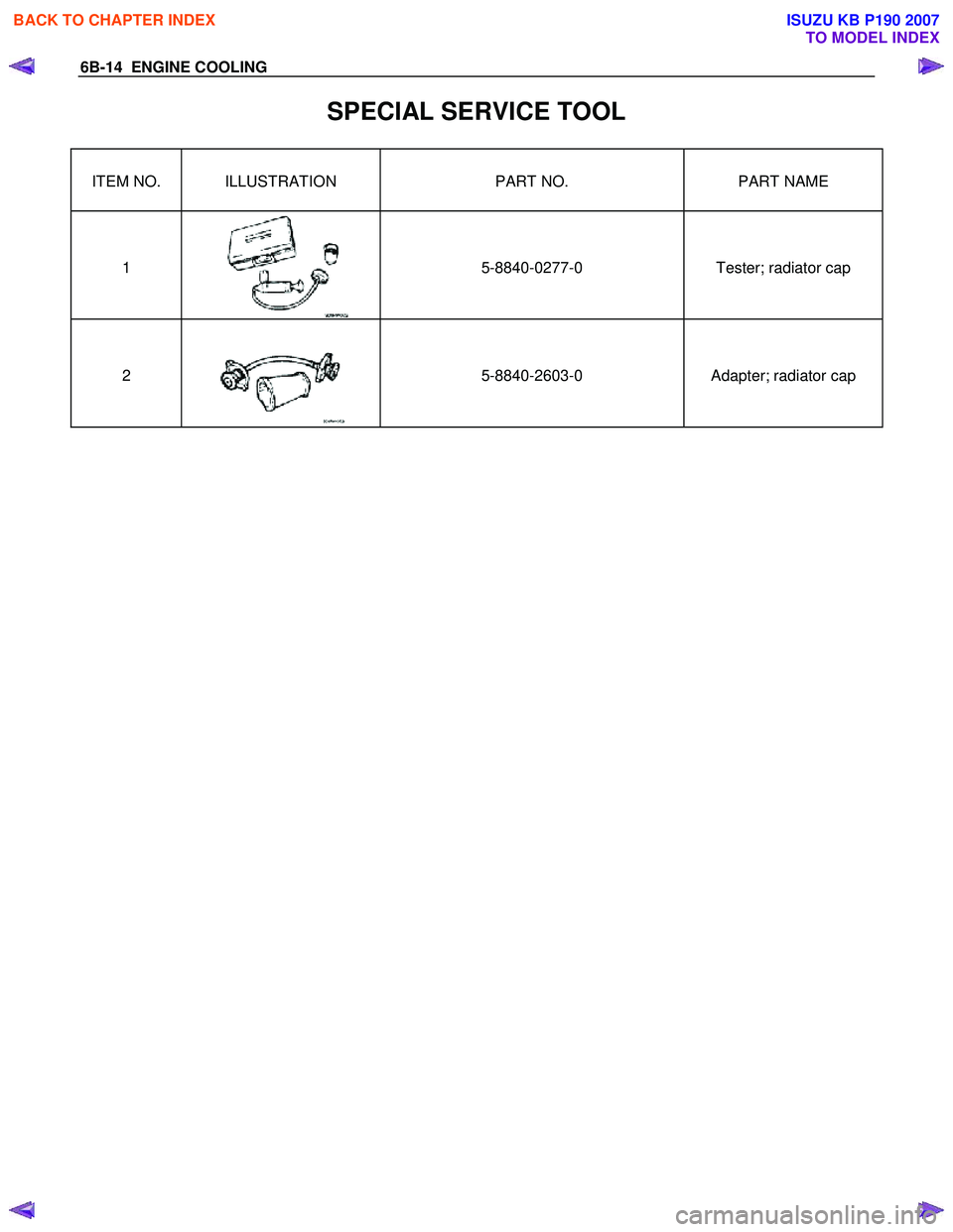
SPECIAL SERVICE TOOL
ITEM NO. ILLUSTRATION PART NO. PART NAME
1
5-8840-0277-0
Tester; radiator cap
2
5-8840-2603-0
Adapter; radiator cap
BACK TO CHAPTER INDEX
TO MODEL INDEX
ISUZU KB P190 2007