2007 ISUZU KB P190 service
[x] Cancel search: servicePage 1310 of 6020
6E-276 Engine Control System (4JH1)
1. Connect the scan tool to the vehicle DLC, with theengine and the scan tool OFF.
2. Turn ON the scan tool.
3. Select Diagnostic > appropriate vehicle identification > Powertrain > 4JH1-TC >
Programming > Program VIN.
4. Input correct VIN reading from stamped VIN o
r
affixed VIN plate on the vehicle.
Select Lock ECU and lock the programmed VIN.
Service Programming System (SPS)
Description
The service programming system (SPS) allows a
technician to program a control module through the data
link connector (DLC). The information transfer circuit that
is used at the DLC is the same serial data circuit used be
the scan tool for retrieving diagnostic trouble codes
(DTCs), displaying data, clearing DTCs etc. This
procedure offers the ability to install software/calibrations
matched to a particular vehicle.
Most control modules have two types of memory. The
software/calibrations reside in the flash memory. The two
types of memory are listed below: • Electrically Erasable Programmable Read Onl
y
Memory (EEPROM).
This type of memory allows selected portions o
f
memory to be programmed while other portions
remain unchanged.
Certain learned values reside in the EEPROM, such as:
- The vehicle identification number (VIN)
- The software/calibrations identification numbers
- The control module security information
• Flash Read Only Memory-Flash Memory
Flash memory has increased memory storage capacity. During programming, all information within
this type of memory is erased, and then replaced
with entirely new information.
Service Programming Methods
The two methods of programming an engine control
module (ECM) are listed below: • Remote Programming
• Pass Thru Programming
For information on programming an ECM using one o
f
the methods listed above, refer to Service Programming
System (SPS) (Remote Procedure) or Service
Programming System (SPS) (Pass-Thru Procedure).
Before Programming a Control Module
Important:
DO NOT program an existing ECM with the identical
software/calibration package. This procedure is not a
short cut to correct the driveability condition. This is an
ineffective repair. An ECM should only be programmed
when the following occurs: • W hen a service procedure instructs you to replace
the ECM. W hen the ECM from another vehicle is
installed, VIN must be changed. And change
vehicle information as necessary such as type o
f
transmission.
• An updated software/calibrations is released.
Ensure that the following conditions are met before
programming an ECM: • The scan tool PCMCIA card is programmed with
the latest software.
• The TIS 2000 is installed with the latest software.
• The hardware key is plugged into the compute
r
port.
• Vehicle system voltage:
- There are no charging system concerns. All charging system concerns must be repaired
before programming the ECM.
- The battery voltage is greater than 12 volts bu
t
less than 16 volts. The battery must be fully
charged before programming the ECM.
-
A battery charger is NOT connected to the
vehicles battery. Incorrect system voltage o
r
voltage fluctuations from a battery charger may
cause programming failure or ECM damage.
- Turn OFF or disable any system that may put a load on the vehicles battery. Turn OFF o
r
disable systems such as:
◊ Heating, ventilation, and air conditioning
(HVAC) systems
◊ Headlights
◊ Room lights
◊ Accessory equipment
• The ignition switch is in the proper position. The
scan tool prompts you to turn ON the ignition, with
the engine OFF. DO NOT change the position o
f
the ignition switch during the programming
procedure unless instructed to do so.
• All tool connections are secure:
- The RS-232 cable
- The connection at the DLC
- The voltage supply circuits
BACK TO CHAPTER INDEX
TO MODEL INDEX
ISUZU KB P190 2007
Page 1311 of 6020
Engine Control System (4JH1) 6E-277
• DO NOT disturb the tool harnesses while
programming. If an interruption occurs during the
programming procedure, programming failure o
r
ECM damage may occur.
• If you are performing the Pass-Thru programming
procedure using a notebook computer without the
power cord, ensure that the internal battery is full
y
charged.
Service Programming System (SPS)
(Remote Procedure)
The Remote Service Programming System (SPS)
method is a three-step process that involves the
following procedures: 1. Connecting the scan tool to the vehicle and obtaining the information from the engine control
module (ECM).
2. Connecting the scan tool to the terminal and downloading a new calibration file from the terminal
into the scan tool memory.
3. Reconnecting the scan tool to the vehicle and uploading the new calibration file into the ECM.
Performing the Remote Procedure 1. Connect the scan tool to the vehicle and obtain the ECM information using the following procedure:
Important:
Ensure the ECM is installed in the vehicle and the batter
y
is fully charged before programming. a. Connect the scan tool to the vehicle data linkconnector (DLC), with the engine and the scan
tool OFF.
b. Turn ON the scan tool.
c. Press Enter at the title screen.
d. Turn ON the ignition, with the engine OFF.
e. Select Service Programming System at the Main Menu.
f. Select Request Info.
g. If there is already stored in the scan tool, the existing data is displayed on the screen. The
scan tool asks user to keep existing data Keep
Data or Continue to request new vehicle
information from the ECM. If there is no data in
the scan tool, it will immediately start vehicle
identification.
h. Enter the vehicle description by following the on- screen instructions based on stamped VIN o
r
affixed VIN plate on the vehicle.
i. During obtaining information, the scan tool is
receiving information from any modules at the
same time. But only ECM information is
displayed on the screen.
j. Turn OFF all accessories and select Continue.
k. Verify that the correct VIN is entered on the scan tool. If the VIN is incorrect, write down the
correct VIN.
2. Turn OFF the scan tool.
3. Disconnect the scan tool from the vehicle.
4. Turn OFF the ignition.
5. Transfer the data from the terminal to the scan tool using the following procedure:
Important:
The TIS supports service programming with the scan
tool scan tool only. a. Connect the scan tool to the terminal.
b. Launch the TIS application at the terminal.
c. Select the Service Programming System at the main screen.
d. Highlight the following information on the Selec
t
Diagnostic Tool and Programming Process
screen: • Select Diagnostic Tool-Select scan tool.
• Select Programming Process-Identif
y
whether an existing ECM is being
reprogrammed or an ECM is being
replaced with a new one.
• Select ECU Location-Select Vehicle.
e. Select Next.
f. Verify the connections on the Preparing fo
r
Communication screen and select Next.
g. Verify the VIN on the Validate Vehicle Identification Number (VIN) screen and selec
t
Next.
Important:
If the ECM is replaced to new one, VIN does no
t
displayed. Input correct VIN reading from stamped VIN
or affixed VIN plate on the vehicle. If the ECM from
another vehicle is installed, input correct VIN by same
way.
h. Highlight Engine on the System Type screen and select Next, if requested.
i. Complete the following information based on the service ID plate on the Validate Vehicle
Data screen until Next is highlighted: • Model
• Model Year
• Engine
• Type of Transmission
BACK TO CHAPTER INDEX
TO MODEL INDEX
ISUZU KB P190 2007
Page 1312 of 6020
6E-278 Engine Control System (4JH1)
• Destination Code
j. Select Next.
k. Verify your selection on the Summary screen.
Important:
Refer to Service Bulletins before service programming is
performed if the bulletins are listed along with the
calibration files.
Important:
Select Cancel if you receive a message stating that the
calibration selected is already the current calibration in
the ECM and reprogramming with the same download is
not allowed.
l. Select Reprog.
m. The Transfer Data screen will appear until the progress bar reaches 100%.
6. Close the application and return to the TIS application selection screen after the download is
complete.
7. Turn OFF the scan tool.
8. Disconnect the scan tool from the terminal.
9. Transfer the data from the scan tool to the ECM using the following procedure:
a. Connect the scan tool to the vehicle DLC, with the engine and the scan tool OFF.
b. Turn ON the scan tool.
c. Press Enter at the Title screen.
d. Turn ON the ignition, with the engine OFF.
e. Select Service Programming System.
f. Select the Program ECU on the scan tool.
g. Follow the on-screen instructions and select Continue.
h. Programming in Process will appear until the progress bar reaches 100%.
Important:
The vehicle fitted with automatic transmission, Check
Trans lamp may blink while programming the ECM since
communication between the ECM and TCM is
interrupted. Clear DTC in any module afte
r
programming.
i. Select Continue and exit the program after the scan tool displays Programming W as
Successful.
10. Turn OFF the ignition.
11. Turn OFF the scan tool.
12. Disconnect the scan tool from the vehicle.
Service Programming System (SPS) (Pass-
Thru Procedure)
Pass-Thru programming allows the scan tool to remain
connected to the terminal and to the vehicle throughou
t
the programming process. The vehicle must be in close
proximity to the terminal while using Pass-Thru.
Important:
The TIS supports service programming with the scan
tool scan tool only.
1. Launch the TIS application at the terminal.
2. Select the Service Programming System at the main screen.
3. Highlight the following information on the Selec
t
Diagnostic Tool and Programming Process screen:
• Select Diagnostic Tool-Select Pass-Thru
• Select Programming Process-Identify whethe
r
as existing engine control module (ECM) is
being reprogrammed or an ECM is being
replaced with a new one.
• Select ECU Location-Select Vehicle.
4. Select Next.
5. Complete all vehicle data on the Preparing fo
r
Communication/Determine Vehicle screen until
Next is highlighted.
6. Select Next.
7. Follow the instruction on the Preparing fo
r
Communication screen.
Important:
In order to reduce the potential for signal loss, the RS-
232 cable should not be more than 25 feet long.
8. Select Next.
9. Verify the VIN on the Validate Vehicle Identification Number (VIN) screen and select Next.
Important:
If the ECM is replaced to new one, VIN does no
t
displayed. Input correct VIN reading from stamped VIN
or affixed VIN plate on the vehicle. If the ECM from
another vehicle is installed, input correct VIN by same
way. 10. Highlight Engine on the System Type screen and
select Next, if requested.
11. Complete the following information based on the service ID plate on the Validate Vehicle Data
screen until Next is highlighted:
• Model
• Model Year
• Engine
• Type of Transmission
• Destination Code
12. Select Next.
13. Verify your selection on the Summary screen.
BACK TO CHAPTER INDEX
TO MODEL INDEX
ISUZU KB P190 2007
Page 1313 of 6020
Engine Control System (4JH1) 6E-279
Important:
Refer to Service Bulletins before service programming is
performed if the bulletins are listed along with the
calibration files.
Important:
Select Cancel if you receive a message stating that the
calibration selected is already the current calibration in
the scan tool and reprogramming with the same
download is not allowed.
14. Select Reprog.
15. The Transfer Data screen will appear until the progress bar reaches 100%.
Important:
The vehicle fitted with automatic transmission, Check
Trans lamp may blink while programming the ECM since
communication between the ECM and TCM is
interrupted. Clear DTC in any module afte
r
programming. 16. Select Close on the Programming Complete
screen.
17. Turn OFF the scan tool.
18. Disconnect the scan tool from the vehicle.
Accelerator Pedal Position (APP) Sensor
Replacement
Removal Procedure 1. Disconnect the negative battery cable.
2. Disconnect the APP sensor connector.
3. Loosen two screws and remove APP sensor from the throttle body.
Installation Procedure 1. Temporary tighten the APP sensor by two screws. 2. Connect a APP sensor connectors to the
APP
sensor.
3. Connect the Tech2 to the vehicle.
4. Connect the negative battery cable.
5. Select "Data Display" with the Tech2.
6. Check the APP sensor data and adjust the
APP
sensor.
7. Tighten two screws.
Crankshaft Position (CKP) Sensor
Replacement
Removal Procedure
1. Disconnect the negative battery cable.
2. Disconnect connector from the CKP sensor.
3. Loosen a bolt and remove the CKP sensor from the clutch housing.
Installation Procedure
1. Install the CKP sensor to the clutch housing.
2. Tighten CKP sensor by a bolt with specified tightening torque.
Tightening Torque
• Bolts: 8.0 - 12.0 N.m (0.8 - 1.2 kgf.m)
3. Connect a CKP sensor connector to the CKP sensor.
4. Connect the negative battery cable.
BACK TO CHAPTER INDEX
TO MODEL INDEX
ISUZU KB P190 2007
Page 1318 of 6020
6E-284 Engine Control System (4JH1)
Important:
To prevent possible electrostatic discharge damage,
follow these guidelines: • Do not touch the ECM connector pins or soldered
components on the ECM circuit board.
• Do not open the replacement part package until
the part is ready to be installed.
• Before removing the part from the package,
ground the package to a known good ground on
the vehicle.
• If the part has been handled while sliding across
the seat, while sitting down from a standing
position, or while walking a distance, touch a
known good ground before installing the part.
• Charge by induction occurs when a person with
well insulated shoes stands near a highly charged
object and momentarily touches ground. Charges
of the same polarity are drained off leaving the
person highly charged with opposite polarity.
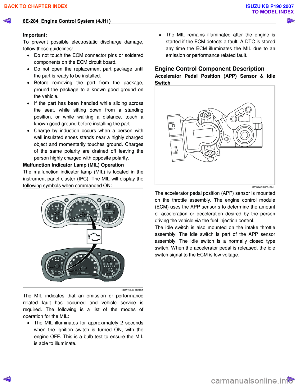
Malfunction Indicator Lamp (MIL) Operation
The malfunction indicator lamp (MIL) is located in the
instrument panel cluster (IPC). The MIL will display the
following symbols when commanded ON:
RTW 76ESH004001
The MIL indicates that an emission or performance
related fault has occurred and vehicle service is
required. The following is a list of the modes o
f
operation for the MIL: • The MIL illuminates for approximately 2 seconds
when the ignition switch is turned ON, with the
engine OFF. This is a bulb test to ensure the MIL
is able to illuminate.
•
The MIL remains illuminated after the engine is
started if the ECM detects a fault. A DTC is stored
any time the ECM illuminates the MIL due to an
emission or performance related fault.
Engine Control Component Description
Accelerator Pedal Position (APP) Sensor & Idle
Switch
RTW 66ESH001301
The accelerator pedal position (APP) sensor is mounted
on the throttle assembly. The engine control module
(ECM) uses the APP sensor s to determine the amount
of acceleration or deceleration desired by the person
driving the vehicle via the fuel injection control.
The idle switch is also mounted on the intake throttle
assembly. The idle switch is part of the APP senso
r
assembly. The idle switch is a normally closed type
switch. W hen the accelerator pedal is released, the idle
switch signal to the ECM is low voltage.
BACK TO CHAPTER INDEX
TO MODEL INDEX
ISUZU KB P190 2007
Page 1334 of 6020
SECTION 6F
EXHAUST SYSTEM
TABLE OF CONTENTS
PAGE
Main Data and Specifications ........................................................................................... 6F - 2
General Description .......................................................................................................... 6 F - 3
Removal and Installation .................................................................................................. 6F - 4
Inspection and Repair ....................................................................................................... 6F - 6
General Description .......................................................................................................... 6 F -7
EGR System Diagram........................................................................................................ 6F 9
Inspection ..................................................................................................................... ..... 6F-11
EGR Cooler (4JA1TC/4JH1TC Euro-III model)................................................................. 6F-12
Turbocharger ................................................................................................................... .. 6F -15
Main Data and Specifications....................................................................................... 6F -15
General Description .......................................................................................................... 6 F -16
Inspection and Repair ....................................................................................................... 6F -17
Special Tools .................................................................................................................. ... 6F -19
IHI Service Network ........................................................................................................... 6F -20
EXH
AU ST SY STEM 6F – 1
BACK TO CHAPTER INDEX
TO MODEL INDEX
ISUZU KB P190 2007
Page 1350 of 6020
EXHAUST SYSTEM 6F – 17
INSPECTION AND REPAIR
Make the necessary adjustments, repairs, and part replacements if excessive wear or damage is discovered during
inspection.
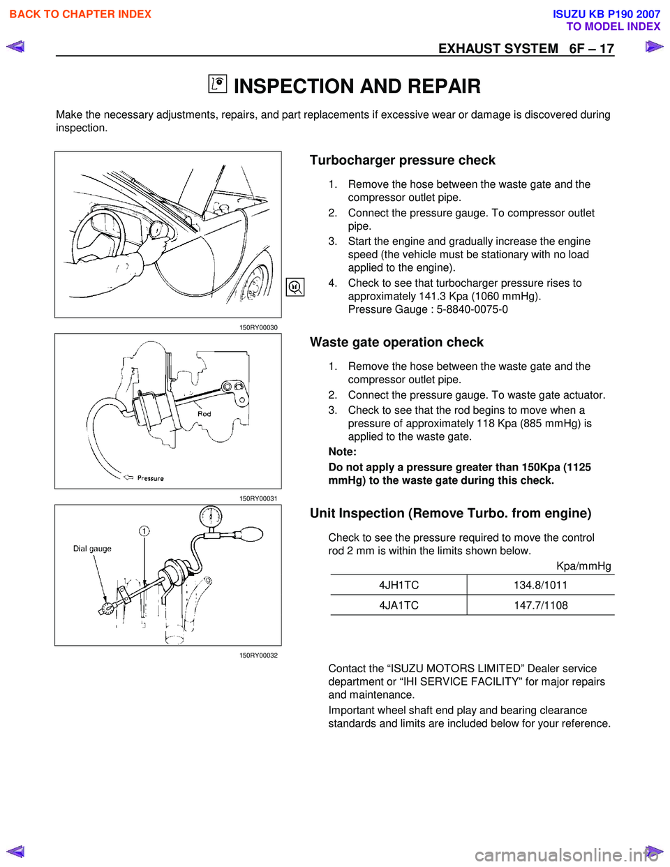
Turbocharger pressure check
1. Remove the hose between the waste gate and the
compressor outlet pipe.
2. Connect the pressure gauge. To compressor outlet pipe.
3. Start the engine and gradually increase the engine speed (the vehicle must be stationary with no load
applied to the engine).
4. Check to see that turbocharger pressure rises to approximately 141.3 Kpa (1060 mmHg).
Pressure Gauge : 5-8840-0075-0
150RY00030
Waste gate operation check
1. Remove the hose between the waste gate and the compressor outlet pipe.
2. Connect the pressure gauge. To waste gate actuator.
3. Check to see that the rod begins to move when a pressure of approximately 118 Kpa (885 mmHg) is
applied to the waste gate.
Note:
Do not apply a pressure greater than 150Kpa (1125
mmHg) to the waste gate during this check.
150RY00031
Unit Inspection (Remove Turbo. from engine)
Check to see the pressure required to move the control
rod 2 mm is within the limits shown below.
Kpa/mmHg
4JH1TC 134.8/1011
4JA1TC 147.7/1108
150RY00032
Contact the “ISUZU MOTORS LIMITED” Dealer service
department or “IHI SERVICE FACILITY” for major repairs
and maintenance.
Important wheel shaft end play and bearing clearance
standards and limits are included below for your reference.
BACK TO CHAPTER INDEX
TO MODEL INDEX
ISUZU KB P190 2007
Page 1353 of 6020
6F – 20 EXHAUST SYSTEM
IHI SERVICE NETWORK
For inquiries relating to turbochargers, please contact your ISUZU distributor or the nearest IHI Turbocharger
Service Facility.
HEADQUART ERS
ISHIKAWAJIMA HARIMA HEAVY INDUSTRIES CO., LTD.(IHI)
General Machinery Division
Tokyo Chuo Building 1-6-2 Marunouchi Chiyoda-ku
Tokyo 100-0005 JAPAN
TEL: 81-(3)-3286-2405 to 2407 (3 lines)
FAX: 81-(3)-3286-2430
CHINA
IHI BEIJING OFFICE
Room 705, China W orld Trade Center, No. 1 Jian Guo Men W ai Avenue
Beijing, People’s Republic of CHINA
TEL: 86-(1)-505-4997, 0408
FAX: 86-(1)-505-4350
TLX: 210343 IHIPK CN
TAIWAN
IHI TAIPEI OFFICE
Room 1202, Chia Hsin Building, No. 96 Chung Shan
North Road, Section 2, Taipei, TAIW AN
TEL: 886-(2)-542-5520, 5521, 5523
FAX: 886-(2)-542-4362
TLX: 11320 IHICO
THAILAND
IHI BANGKOK OFFICE
8th Floor, Thaniya Building, 62 Silom Road, Bangkok, THAILAND
TEL: 66-(2)-236-3490, 7356, 9099
FAX: 66-(2)-236-7340
TLX: 82375 IHICO TH
MALAYSIA
IHI KUALA LUMPUR OFFICE
Letter Box No. 52, 22nd Floor, UBN Tower,
10 Jin. P. Ramlee 50250 Kuala Lumpur, MALAYSIA
TEL: 60-(3)-232-1255, 1271
FAX: 60-(3)-232-1418
TLX: IHI KLMA 20257
INDONESIA
IHI JAKARTA OFFICE
9th Floor, Skyline Building JI. M. H. Thamrin, No. 9, Jakarta, INDONESIA
TEL: 62-(21)-32-2147, 390-2211
FAX: 62-(21)-32-3273
TLX: 44175 IHIJKT
BACK TO CHAPTER INDEX
TO MODEL INDEX
ISUZU KB P190 2007