2007 ISUZU KB P190 brakes
[x] Cancel search: brakesPage 4338 of 6020
7A2-54 TRANSMISSION CONTROL SYSTEM (JR405E)
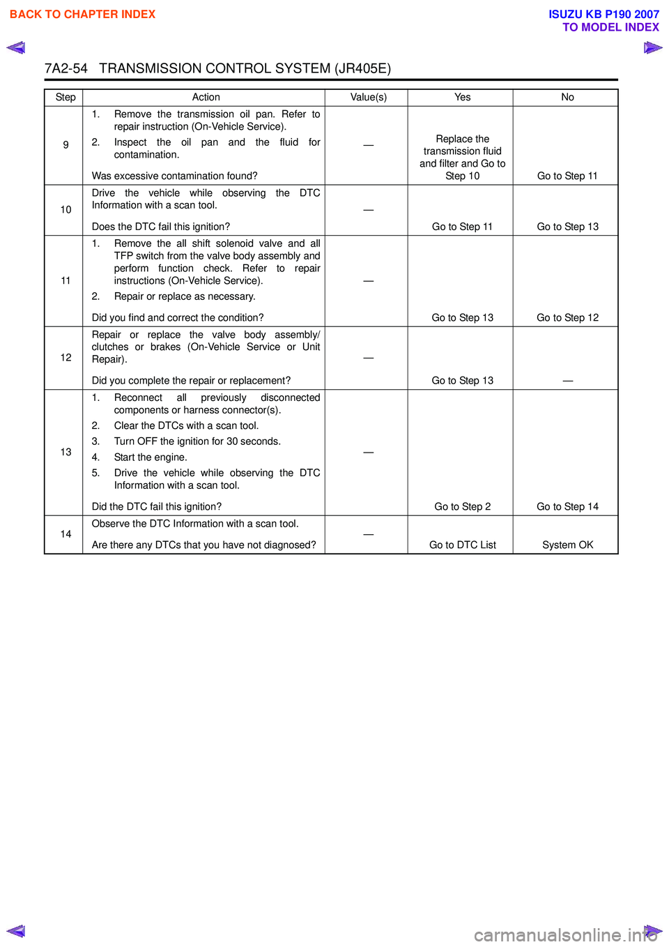
91. Remove the transmission oil pan. Refer to
repair instruction (On-Vehicle Service).
2. Inspect the oil pan and the fluid for contamination.
Was excessive contamination found? —
Replace the
transmission fluid
and filter and Go to Step 10 Go to Step 11
10 Drive the vehicle while observing the DTC
Information with a scan tool.
Does the DTC fail this ignition? —
Go to Step 11 Go to Step 13
11 1. Remove the all shift solenoid valve and all
TFP switch from the valve body assembly and
perform function check. Refer to repair
instructions (On-Vehicle Service).
2. Repair or replace as necessary.
Did you find and correct the condition? —
Go to Step 13 Go to Step 12
12 Repair or replace the valve body assembly/
clutches or brakes (On-Vehicle Service or Unit
Repair).
Did you complete the repair or replacement? —
Go to Step 13 —
13 1. Reconnect all previously disconnected
components or harness connector(s).
2. Clear the DTCs with a scan tool.
3. Turn OFF the ignition for 30 seconds.
4. Start the engine.
5. Drive the vehicle while observing the DTC Information with a scan tool.
Did the DTC fail this ignition? —
Go to Step 2 Go to Step 14
14 Observe the DTC Information with a scan tool.
Are there any DTCs that you have not diagnosed? —
Go to DTC List System OK
Step
Action Value(s)Yes No
BACK TO CHAPTER INDEX
TO MODEL INDEX
ISUZU KB P190 2007
Page 4355 of 6020
TRANSMISSION CONTROL SYSTEM (JR405E) 7A2-71
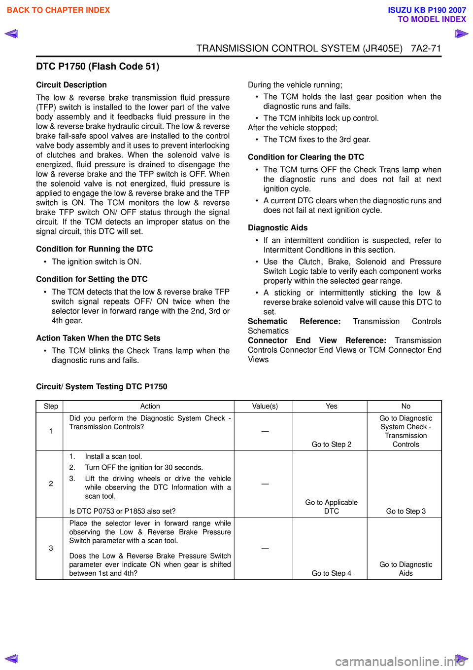
DTC P1750 (Flash Code 51)
Circuit Description
The low & reverse brake transmission fluid pressure
(TFP) switch is installed to the lower part of the valve
body assembly and it feedbacks fluid pressure in the
low & reverse brake hydraulic circuit. The low & reverse
brake fail-safe spool valves are installed to the control
valve body assembly and it uses to prevent interlocking
of clutches and brakes. When the solenoid valve is
energized, fluid pressure is drained to disengage the
low & reverse brake and the TFP switch is OFF. When
the solenoid valve is not energized, fluid pressure is
applied to engage the low & reverse brake and the TFP
switch is ON. The TCM monitors the low & reverse
brake TFP switch ON/ OFF status through the signal
circuit. If the TCM detects an improper status on the
signal circuit, this DTC will set.
Condition for Running the DTC • The ignition switch is ON.
Condition for Setting the DTC • The TCM detects that the low & reverse brake TFP switch signal repeats OFF/ ON twice when the
selector lever in forward range with the 2nd, 3rd or
4th gear.
Action Taken When the DTC Sets • The TCM blinks the Check Trans lamp when the diagnostic runs and fails. During the vehicle running;
• The TCM holds the last gear position when the diagnostic runs and fails.
• The TCM inhibits lock up control.
After the vehicle stopped;
• The TCM fixes to the 3rd gear.
Condition for Clearing the DTC • The TCM turns OFF the Check Trans lamp when the diagnostic runs and does not fail at next
ignition cycle.
• A current DTC clears when the diagnostic runs and does not fail at next ignition cycle.
Diagnostic Aids • If an intermittent condition is suspected, refer to Intermittent Conditions in this section.
• Use the Clutch, Brake, Solenoid and Pressure Switch Logic table to verify each component works
properly within the selected gear range.
• A sticking or intermittently sticking the low & reverse brake solenoid valve will cause this DTC to
set.
Schematic Reference: Transmission Controls
Schematics
Connector End View Reference: Transmission
Controls Connector End Views or TCM Connector End
Views
Circuit/ System Testing DTC P1750
Step Action Value(s)Yes No
1 Did you perform the Diagnostic System Check -
Transmission Controls? —
Go to Step 2 Go to Diagnostic
System Check -
Transmission Controls
2 1. Install a scan tool.
2. Turn OFF the ignition for 30 seconds.
3. Lift the driving wheels or drive the vehicle while observing the DTC Information with a
scan tool.
Is DTC P0753 or P1853 also set? —
Go to Applicable DTC Go to Step 3
3 Place the selector lever in forward range while
observing the Low & Reverse Brake Pressure
Switch parameter with a scan tool.
Does the Low & Reverse Brake Pressure Switch
parameter ever indicate ON when gear is shifted
between 1st and 4th? —
Go to Step 4 Go to Diagnostic
Aids
BACK TO CHAPTER INDEX
TO MODEL INDEX
ISUZU KB P190 2007
Page 4357 of 6020
TRANSMISSION CONTROL SYSTEM (JR405E) 7A2-73
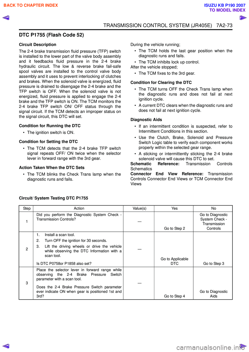
DTC P1755 (Flash Code 52)
Circuit Description
The 2-4 brake transmission fluid pressure (TFP) switch
is installed to the lower part of the valve body assembly
and it feedbacks fluid pressure in the 2-4 brake
hydraulic circuit. The low & reverse brake fail-safe
spool valves are installed to the control valve body
assembly and it uses to prevent interlocking of clutches
and brakes. When the solenoid valve is energized, fluid
pressure is drained to disengage the 2-4 brake and the
TFP switch is OFF. When the solenoid valve is not
energized, fluid pressure is applied to engage the 2-4
brake and the TFP switch is ON. The TCM monitors the
2-4 brake TFP switch ON/ OFF status through the
signal circuit. If the TCM detects an improper status on
the signal circuit, this DTC will set.
Condition for Running the DTC • The ignition switch is ON.
Condition for Setting the DTC • The TCM detects that the 2-4 brake TFP switch signal repeats OFF/ ON twice when the selector
lever in forward range with the 3rd gear.
Action Taken When the DTC Sets • The TCM blinks the Check Trans lamp when the diagnostic runs and fails. During the vehicle running;
• The TCM holds the last gear position when the diagnostic runs and fails.
• The TCM inhibits lock up control.
After the vehicle stopped;
• The TCM fixes to the 3rd gear.
Condition for Clearing the DTC • The TCM turns OFF the Check Trans lamp when the diagnostic runs and does not fail at next
ignition cycle.
• A current DTC clears when the diagnostic runs and does not fail at next ignition cycle.
Diagnostic Aids • If an intermittent condition is suspected, refer to Intermittent Conditions in this section.
• Use the Clutch, Brake, Solenoid and Pressure Switch Logic table to verify each component works
properly within the selected gear range.
• A sticking or intermittently sticking the 2-4 brake solenoid valve will cause this DTC to set.
Schematic Reference: Transmission Controls
Schematics
Connector End View Reference: Transmission
Controls Connector End Views or TCM Connector End
Views
Circuit/ System Testing DTC P1755
Step Action Value(s)Yes No
1 Did you perform the Diagnostic System Check -
Transmission Controls? —
Go to Step 2 Go to Diagnostic
System Check -
Transmission Controls
2 1. Install a scan tool.
2. Turn OFF the ignition for 30 seconds.
3. Lift the driving wheels or drive the vehicle while observing the DTC Information with a
scan tool.
Is DTC P0758or P1858 also set? —
Go to Applicable DTC Go to Step 3
3 Place the selector lever in forward range while
observing the 2-4 Brake Pressure Switch
parameter with a scan tool.
Does the 2-4 Brake Pressure Switch parameter
ever indicate ON when gear is positioned 1st and
3rd? —
Go to Step 4 Go to Diagnostic
Aids
BACK TO CHAPTER INDEX
TO MODEL INDEX
ISUZU KB P190 2007
Page 4405 of 6020
TRANSMISSION CONTROL SYSTEM (JR405E) 7A2-121
Test Instructions
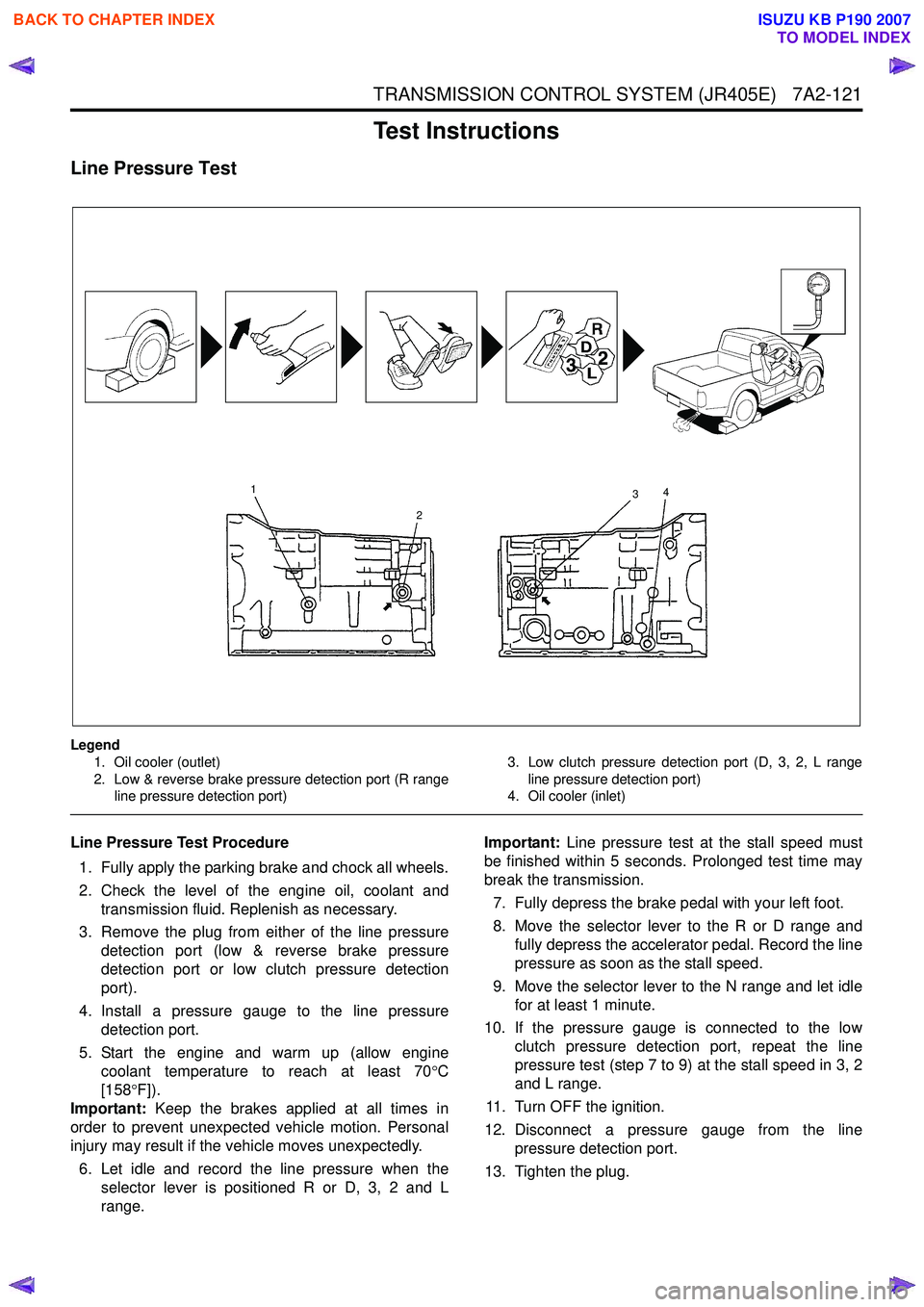
Line Pressure Test
Legend1. Oil cooler (outlet)
2. Low & reverse brake pressure detection port (R range line pressure detection port) 3. Low clutch pressure detection port (D, 3, 2, L range
line pressure detection port)
4. Oil cooler (inlet)
Line Pressure Test Procedure
1. Fully apply the parking brake and chock all wheels.
2. Check the level of the engine oil, coolant and transmission fluid. Replenish as necessary.
3. Remove the plug from either of the line pressure detection port (low & reverse brake pressure
detection port or low clutch pressure detection
port).
4. Install a pressure gauge to the line pressure detection port.
5. Start the engine and warm up (allow engine coolant temperature to reach at least 70 °C
[158 °F]).
Important: Keep the brakes applied at all times in
order to prevent unexpected vehicle motion. Personal
injury may result if the vehicle moves unexpectedly.
6. Let idle and record the line pressure when the selector lever is positioned R or D, 3, 2 and L
range. Important:
Line pressure test at the stall speed must
be finished within 5 seconds. Prolonged test time may
break the transmission.
7. Fully depress the brake pedal with your left foot.
8. Move the selector lever to the R or D range and fully depress the accelerator pedal. Record the line
pressure as soon as the stall speed.
9. Move the selector lever to the N range and let idle for at least 1 minute.
10. If the pressure gauge is connected to the low clutch pressure detection port, repeat the line
pressure test (step 7 to 9) at the stall speed in 3, 2
and L range.
11. Turn OFF the ignition.
12. Disconnect a pressure gauge from the line pressure detection port.
13. Tighten the plug.
1
2 3
4
BACK TO CHAPTER INDEX
TO MODEL INDEX
ISUZU KB P190 2007
Page 4408 of 6020
7A2-124 TRANSMISSION CONTROL SYSTEM (JR405E)
Time Lag Test
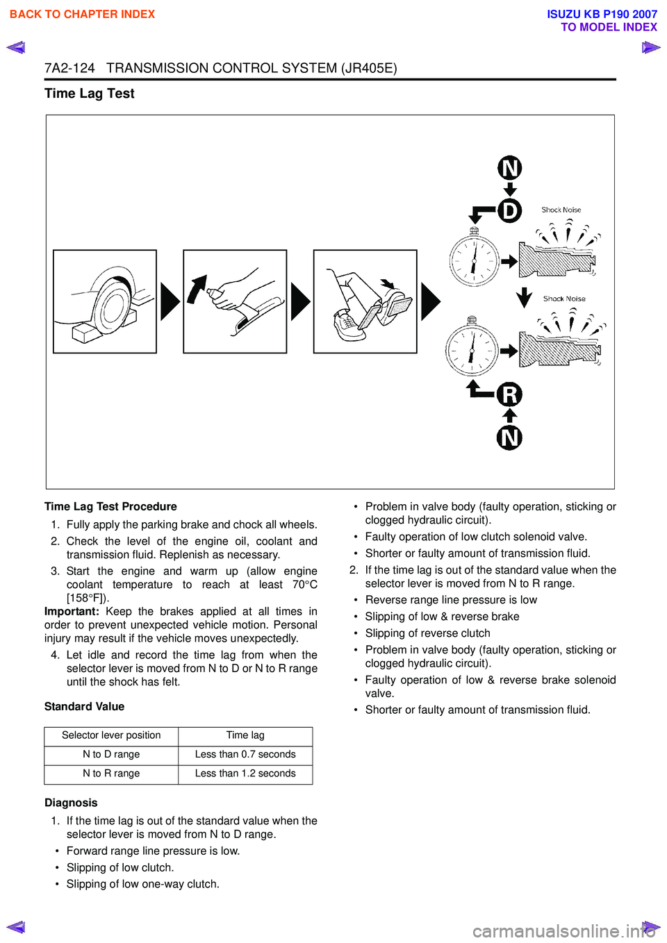
Time Lag Test Procedure1. Fully apply the parking brake and chock all wheels.
2. Check the level of the engine oil, coolant and transmission fluid. Replenish as necessary.
3. Start the engine and warm up (allow engine coolant temperature to reach at least 70 °C
[158 °F]).
Important: Keep the brakes applied at all times in
order to prevent unexpected vehicle motion. Personal
injury may result if the vehicle moves unexpectedly.
4. Let idle and record the time lag from when the selector lever is moved from N to D or N to R range
until the shock has felt.
Standard Value
Diagnosis 1. If the time lag is out of the standard value when the selector lever is moved from N to D range.
• Forward range line pressure is low.
• Slipping of low clutch.
• Slipping of low one-way clutch. • Problem in valve body (faulty operation, sticking or
clogged hydraulic circuit).
• Faulty operation of low clutch solenoid valve.
• Shorter or faulty amount of transmission fluid.
2. If the time lag is out of the standard value when the selector lever is moved from N to R range.
• Reverse range line pressure is low
• Slipping of low & reverse brake
• Slipping of reverse clutch
• Problem in valve body (faulty operation, sticking or clogged hydraulic circuit).
• Faulty operation of low & reverse brake solenoid valve.
• Shorter or faulty amount of transmission fluid.
Selector lever position Time lag
N to D range Less than 0.7 seconds
N to R range Less than 1.2 seconds
BACK TO CHAPTER INDEX
TO MODEL INDEX
ISUZU KB P190 2007
Page 4428 of 6020
7A2-144 TRANSMISSION CONTROL SYSTEM (JR405E)
The JR405E automatic transmission is electrically
controlled by a transmission control module (TCM).
There are four forward speeds and one reverse speed.
This JR405E automatic transmission employs a clutch
pressure direct control system (Direct Electronic Shift
Control: DESC) using duty cycle type solenoid valves,
which ensure high shift quality. This transmission also
has a learning function and constantly checks the time
of each clutch and brake required for the shift in order
to match this time with the target value for the optimum
shift. The TCM will automatically select the most
appropriate shift points and lock-up points depending
on the accelerator pedal opening, the vehicle speed
and the vehicle load. If any trouble arises in the speed
sensor, solenoid valve, etc., the fail-safe control
function is activated to keep the running performance.
The JR405E automatic transmission consists of the
torque converter, oil pump, input shaft, out put shaft,
planetary gears and valve body. The gear train consists
of two planetary gear sets and three multiple plate
clutches in combination with two multiple plate brakes
and a one-way clutch.
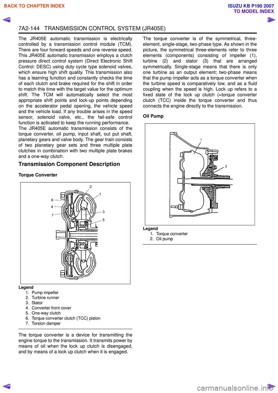
Transmission Component Description
Torque Converter
Legend
1. Pump impeller
2. Turbine runner
3. Stator
4. Converter front cover
5. One-way clutch
6. Torque converter clutch (TCC) piston
7. Torsion damper
The torque converter is a device for transmitting the
engine torque to the transmission. It transmits power by
means of oil when the lock up clutch is disengaged,
and by means of a lock up clutch when it is engaged. The torque converter is of the symmetrical, three-
element, single-stage, two-phase type. As shown in the
picture, the symmetrical three-elements refer to three
elements (components) consisting of impeller (1),
turbine (2) and stator (3) that are arranged
symmetrically. Single-stage means that there is only
one turbine as an output element; two-phase means
that the pump impeller acts as a torque converter when
the turbine speed is comparatively low, and as a fluid
coupling when the speed is high. Lock up refers to a
fixed state of the lock up clutch (=torque converter
clutch (TCC) inside the torque converter and thus
connects the engine directly to the transmission.
Oil Pump
Legend 1. Torque converter
2. Oil pump
BACK TO CHAPTER INDEX
TO MODEL INDEX
ISUZU KB P190 2007
Page 4430 of 6020
7A2-146 TRANSMISSION CONTROL SYSTEM (JR405E)
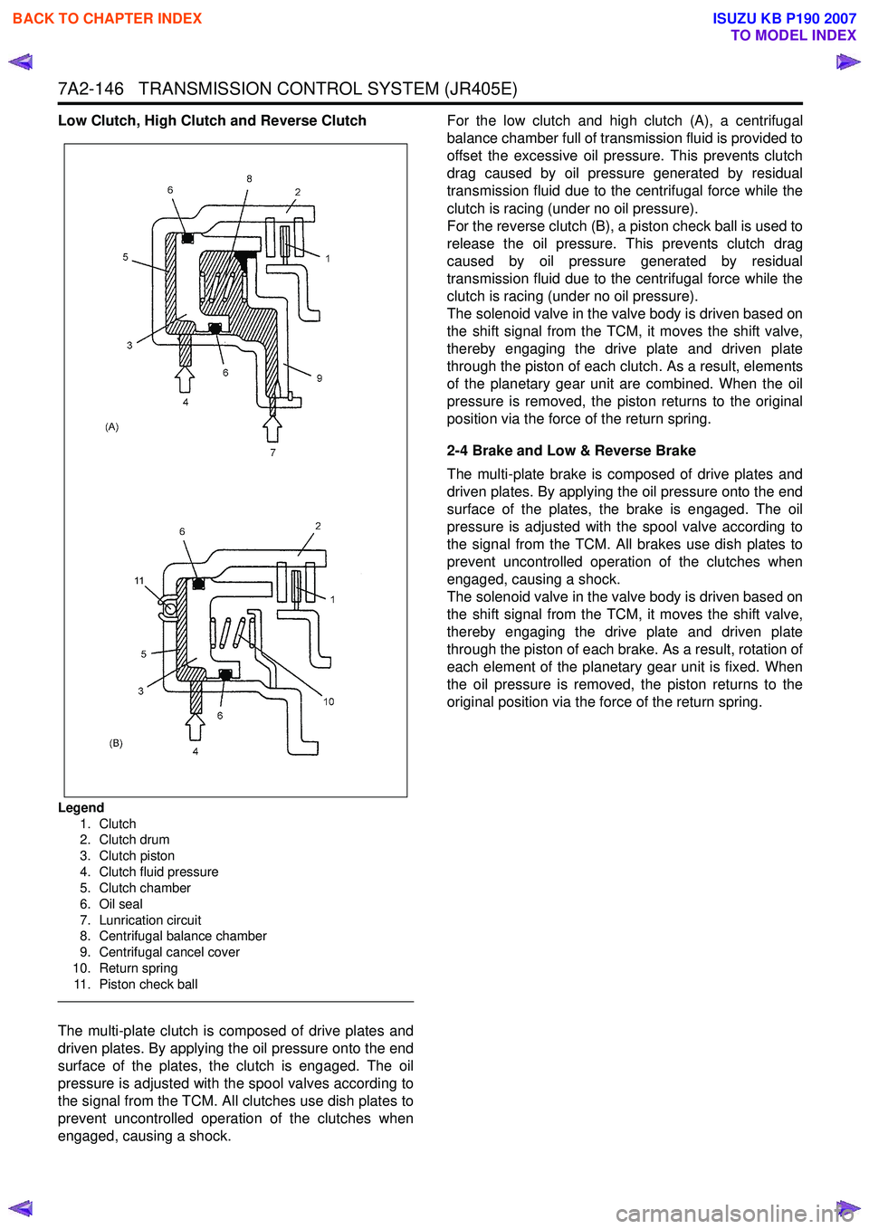
Low Clutch, High Clutch and Reverse Clutch
Legend1. Clutch
2. Clutch drum
3. Clutch piston
4. Clutch fluid pressure
5. Clutch chamber
6. Oil seal
7. Lunrication circuit
8. Centrifugal balance chamber
9. Centrifugal cancel cover
10. Return spring 11. Piston check ball
The multi-plate clutch is composed of drive plates and
driven plates. By applying the oil pressure onto the end
surface of the plates, the clutch is engaged. The oil
pressure is adjusted with the spool valves according to
the signal from the TCM. All clutches use dish plates to
prevent uncontrolled operation of the clutches when
engaged, causing a shock. For the low clutch and high clutch (A), a centrifugal
balance chamber full of transmission fluid is provided to
offset the excessive oil pressure. This prevents clutch
drag caused by oil pressure generated by residual
transmission fluid due to the centrifugal force while the
clutch is racing (under no oil pressure).
For the reverse clutch (B), a piston check ball is used to
release the oil pressure. This prevents clutch drag
caused by oil pressure generated by residual
transmission fluid due to the centrifugal force while the
clutch is racing (under no oil pressure).
The solenoid valve in the valve body is driven based on
the shift signal from the TCM, it moves the shift valve,
thereby engaging the drive plate and driven plate
through the piston of each clutch. As a result, elements
of the planetary gear unit are combined. When the oil
pressure is removed, the piston returns to the original
position via the force of the return spring.
2-4 Brake and Low & Reverse Brake
The multi-plate brake is composed of drive plates and
driven plates. By applying the oil pressure onto the end
surface of the plates, the brake is engaged. The oil
pressure is adjusted with the spool valve according to
the signal from the TCM. All brakes use dish plates to
prevent uncontrolled operation of the clutches when
engaged, causing a shock.
The solenoid valve in the valve body is driven based on
the shift signal from the TCM, it moves the shift valve,
thereby engaging the drive plate and driven plate
through the piston of each brake. As a result, rotation of
each element of the planetary gear unit is fixed. When
the oil pressure is removed, the piston returns to the
original position via the force of the return spring.
BACK TO CHAPTER INDEX
TO MODEL INDEX
ISUZU KB P190 2007
Page 4445 of 6020
TRANSMISSION CONTROL SYSTEM (JR405E) 7A2-161
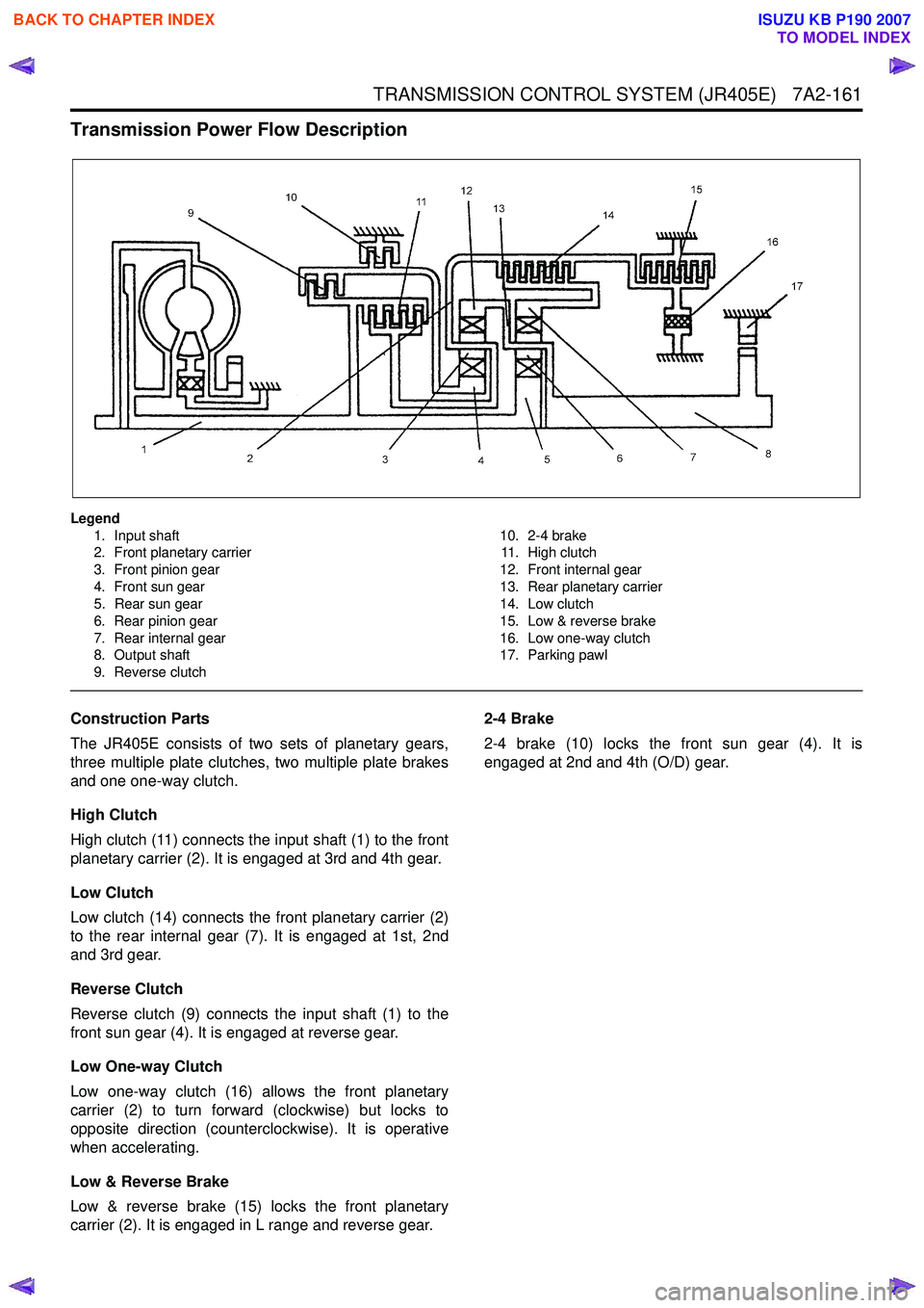
Transmission Power Flow Description
Legend1. Input shaft
2. Front planetary carrier
3. Front pinion gear
4. Front sun gear
5. Rear sun gear
6. Rear pinion gear
7. Rear internal gear
8. Output shaft
9. Reverse clutch 10. 2-4 brake
11. High clutch
12. Front internal gear
13. Rear planetary carrier
14. Low clutch
15. Low & reverse brake
16. Low one-way clutch
17. Parking pawl
Construction Parts
The JR405E consists of two sets of planetary gears,
three multiple plate clutches, two multiple plate brakes
and one one-way clutch.
High Clutch
High clutch (11) connects the input shaft (1) to the front
planetary carrier (2). It is engaged at 3rd and 4th gear.
Low Clutch
Low clutch (14) connects the front planetary carrier (2)
to the rear internal gear (7). It is engaged at 1st, 2nd
and 3rd gear.
Reverse Clutch
Reverse clutch (9) connects the input shaft (1) to the
front sun gear (4). It is engaged at reverse gear.
Low One-way Clutch
Low one-way clutch (16) allows the front planetary
carrier (2) to turn forward (clockwise) but locks to
opposite direction (counterclockwise). It is operative
when accelerating.
Low & Reverse Brake
Low & reverse brake (15) locks the front planetary
carrier (2). It is engaged in L range and reverse gear. 2-4 Brake
2-4 brake (10) locks the front sun gear (4). It is
engaged at 2nd and 4th (O/D) gear.
BACK TO CHAPTER INDEX
TO MODEL INDEX
ISUZU KB P190 2007