Page 765 of 6020
5C-66 BRAKES
4JA1-T/4JH1-TC RHD MODEL
RTW 75CMF001101
4JJ1-TC/4JK1-TC RHD MODEL
RTW 75CMF001301
BACK TO CHAPTER INDEX
TO MODEL INDEX
ISUZU KB P190 2007
Page 766 of 6020
BRAKES 5C-67
C24SE RHD MODEL
RTW 75CMF001401
HFV6 RHD MODEL
RTW 75CMF001601
BACK TO CHAPTER INDEX
TO MODEL INDEX
ISUZU KB P190 2007
Page 767 of 6020
5C-68 BRAKES
4JA1-T/4JH1-TC LHD MODEL
RTW 75CMF001201
4JJ1-TC/4JK1-TC LHD MODEL
RUW 75CLF000201
BACK TO CHAPTER INDEX
TO MODEL INDEX
ISUZU KB P190 2007
Page 768 of 6020
BRAKES 5C-69
C24SE LHD MODEL
RTW 75CMF001501
HFV6 LHD MODEL
RTW 75CMF001701
BACK TO CHAPTER INDEX
TO MODEL INDEX
ISUZU KB P190 2007
Page 769 of 6020
5C-70 BRAKES
Special Tools
ILLUSTRATION PART NO.
PART NAME
5-8840-2190-0
Pressure Tester; Brake Oil
BACK TO CHAPTER INDEX
TO MODEL INDEX
ISUZU KB P190 2007
Page 781 of 6020

PARKING BRAKE SYSTEM 5D-11
Inspection and Repair
Brake Lining Inspection
Check the shoe assemblies for wear by removing the
brake drum.
Replace the shoe assemblies if the lining thickness is
less than 1.0 mm (0.039 in).
Minimum limit: 1.0 mm (0.039 in)
308RS004
Parking Brake Adjustment
NOTE: All brakes are self-adjusting. Brakes are
adjusted by repeated stepping on the brake pedal.
(After stepping on the pedal and releasing it, the rea
r
brake auto-adjuster produces a clicking sound. The
same operation should be repeated until the sound
disappears.)
Take the following steps after overhauling the rea
r
brake assembly.
1. Move the parking brake lever to its fully released position.
2. Parking brake cable must be loosened sufficiently.
(Loosen the adjust nut.)
3. Repeat stepping on the brake pedal firmly, and releasing it until the clicking sound can no longe
r
be heard.
If the difference between the brake drum inside
diameter and the brake shoes external diameter is
adjusted to be 0.4 mm (0.0157 in), the number o
f
times for depressing the brake pedal can be
reduced.
4. Remove the drum. Measure the brake drum inside
diameter and the brake shoes external diameter.
Total shoe clearance: 0.4 mm (0.0157 in)
If incorrect, readjust the brake shoe clearance.
5. Rotate the adjust nut of hand brake lever until all slack disappears from the cable. Set the adjust
nut.
6. After the rear brake shoe/drum gap has been adjusted, perform parking brake cable adjustment.
7. Turn the adjusting nut so that the parking brake lever travels 6 −9 notches (Bucket Seat) or 8 −14
notches (Bench Seat) when pulled up with a force
of 294 N (30 kg/66 lb).
8. Make sure there is no brake dragging.
BACK TO CHAPTER INDEX
TO MODEL INDEX
ISUZU KB P190 2007
Page 3257 of 6020

Engine Management – V6 – General Information Page 6C1-1–15
W hen the cruise control ON-OFF switch, located on the right hand side of the dash panel, is pressed, the PIM, on
receiving the input from the switch, turns on the cruise ON-OFF switch warning lamp to inform the user that the cruise
control has been engaged.
W hen the cruise control switch assembly is pressed to SET/COAST, the PIM on receiving the input, sends a signal via
the serial data bus to the ECM. Providing the pre-conditions for cruise control operation have been met, the ECM
activates cruise control and commands the PIM to turn on the instrument cluster cruise set warning lamp, to inform the
user that cruise control is active. The ECM receives all the various inputs required to maintain the correct speed and then
controls the throttle plate depending on the load on the engine (ascending or descending hills, etc).
The cruise control is deactivated by either pressing the brake pedal, clutch pedal, cruise CANCEL or by the cruise control
ON-OFF button. In each of these instances, the ECM receives an input when any of these switches are activated. For
further information on the cruise control system, refer to 8C Cruise Control – HFV6.
3.7 Brake Torque Management
Brake torque management places limits on engine torque when the brakes are applied, regardless of the accelerator
pedal position (APP). The conditions under which brake torque management occur are as follows:
• The accelerator has been depressed before the brakes are applied,
• The brakes are applied and the ECM receives an input from the stop lamp switch,
• Vehicle speed is greater than 5 km/h,
• Engine speed is greater than 1200 rpm and
• Conditions exist for greater than 2.5 seconds.
W hen brake torque management has been implemented, the torque is reduced by altering the throttle plate opening by
25%. The ECM will monitor the rate at which the vehicle is slowing and adjust the throttle plate opening accordingly.
3.8 Emission Control Systems
Evaporative Emission Control System
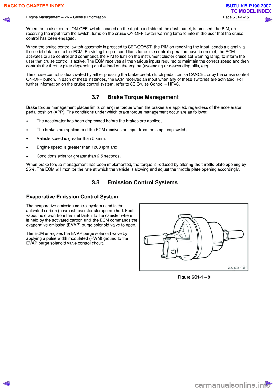
The evaporative emission control system used is the
activated carbon (charcoal) canister storage method. Fuel
vapour is drawn from the fuel tank into the canister where it
is held by the activated carbon until the ECM commands the
evaporative emission (EVAP) purge solenoid valve to open.
The ECM energises the EVAP purge solenoid valve by
applying a pulse width modulated (PW M) ground to the
EVAP purge solenoid valve control circuit.
Figure 6C1-1 – 9
BACK TO CHAPTER INDEX
TO MODEL INDEX
ISUZU KB P190 2007
Page 3530 of 6020

Engine Management – V6 – Service Operations Page 6C1-3–6
Basic Diagnostic Tools Required
Use of incorrect electrical circuit diagnostic
tools when performing certain service
procedures could result in incorrect
diagnostic results or damage to components.
The following electrical circuit testing tools are required to perform the diagnostic procedures detailed in this Section:
• Test lamp, refer to 8A Electrical – Body and Chassis for further information.
• Digital multimeter with 10 M Ω ohms impedance, refer to 8A Electrical – Body and Chassis for further information.
• Connector test adapter kit Tool No. J35616-A.
1.3 Service Operations Not Covered In This
Section
There are situations where components and/or procedures related to the powertrain management system are covered in
other Sections of the service documentation. To aid technicians in locating the necessary service procedures for these
components and/or procedures, refer to the stated references.
Air-conditioning System
For A/C pressure switch replacement procedure, refer to 2A Heater and Air-conditioning.
Electrical Components
For the following electrical system component replacement procedures, refer to the appropriate Sections as follows:
• Extended brake pedal travel switch and stop lamp switch service operations, refer to 5C Brakes.
• Fuse and relay locations, refer to 8A Electrical-Body and Chassis.
• Cruise control switch assembly service operations, refer to 8C Cruise Control – HFV6.
• Powertrain interface module PIM removal and installation procedure, refer to 6E1 Powertrain Interface Module – V6.
• Neutral start and back-up lamp switch, refer to 7C4 Automatic Transmission – 4L60E – On-vehicle Servicing.
• Vehicle speed sensor service operations, refer to:
− 7C4 Automatic Transmission – 4L60E – On-vehicle Servicing
− 7B1 Manual Transmission – V6
Fuel System
For the following fuel system component replacement procedures, refer to 6C Fuel System – V6.
• Fuel system cleaning,
• Fuel system leak and pressure test,
• Fuel feed hose to fuel rail replacement,
• Fuel line quick connect fittings,
• Evaporative emission control canister,
• Fuel filter,
• Fuel hose / pipes layout,
• Fuel pump motor assembly and fuel pressure regulator assembly,
• Fuel sender assembly service operations.
BACK TO CHAPTER INDEX
TO MODEL INDEX
ISUZU KB P190 2007