2007 ISUZU KB P190 CIRCUIT DIAGRAM
[x] Cancel search: CIRCUIT DIAGRAMPage 3698 of 6020

Powertrain Interface Module – V6 Page 6E1–37
Step Action Yes No
6
1 Disconnect the PIM harness connector (vehicles with manual
transmission), or TCM harness connector (vehicles with
automatic transmission).
2 Using a digital multimeter, measure the resistance between the two CAN_LO terminals of either the PIM or TCM.
NOTE
Refer to 5 GM LAN Serial Communication Circuit and
6 Wiring Diagram and Connector for the appropriate GM
LAN component terminal identification.
Does the digital multimeter display infinity? Go to Step 8 Go to Step 7
7
Using a digital multimeter, measure the resistance between the two
CAN_HI terminals of either the PIM (vehicles with manual
transmission) or TCM (vehicles with automatic transmission).
Does the digital multimeter display infinity? Go to Step 8 Go to Step 9
8
Replace the PIM (vehicles with manual transmission) or TCM
(vehicles with automatic transmission). Refer to one of the following
for the component replacement procedure:
• 7C4 Automatic Transmission – 4L60E – On-vehicle Servicing, or
• 11.2 Powertrain Interface Module.
Has the repair been completed? Go to Step 11 —
9 Replace the ECM. Refer to 6C1-3 Engine Management – V6 –
Service Operations.
Has the repair been completed? Go to Step 11
—
10
Replace the PIM. Refer to 11.2 Powertrain Interface Module.
Has the repair been completed? Go to Step 11 —
11 1 Using Tech 2, clear the DTCs.
2 Switch off the ignition for 30 seconds.
3 Start the engine.
4 Operate the vehicle within the conditions for running the DTC.
Does DTC U2105 fail this ignition cycle? Go to Step 2 Go to Step 12
12
Using Tech 2, select the DTC display function.
Does Tech 2 display any DTCs? Go to the
appropriate DTC Table System OK
When all diagnosis and repairs are completed, clear all DTCs and check the system for correct operation.
BACK TO CHAPTER INDEX
TO MODEL INDEX
ISUZU KB P190 2007
Page 3699 of 6020
Powertrain Interface Module – V6 Page 6E1–38
9.4 DTC U2106 – CAN Bus No
Communication With Transmission
Control Module
DTC Description
This diagnostic procedure supports DTC U2106 – CAN Bus No Communication W ith TCM (Transmission Control
Module).
Circuit Description
The transmission control module (TCM) and engine control module (ECM) transmit and receive data using the GM LAN
serial data protocol, while the immobiliser control unit (ICU) uses Keyword 2000 serial data protocol.
As the GM LAN and keyword 2000 protocols are not compatible, a powertrain interface module (PIM) is integrated into
the serial data system to enable communication between the two different protocols. The PIM also integrates with the
instrument cluster assembly.
The PIM continuously receives messages from the TCM. If the PIM does not receive a message within a predetermined
time, DTC U2106 sets.
Additional Information
• Refer to 6 W iring Diagram and Connector for the following information:
• PIM connector illustration and terminal assignment, and
• PIM wiring diagram.
• For intermittent fault conditions, refer to Intermittent Fault Conditions.
• Since fault conditions in a wiring connector may trigger DTCs, always test the connectors related to this diagnostic
procedure for shorted terminals or poor wiring connection before replacing any component. Refer to 8A Electrical -
Body and Chassis for information on electrical fault diagnosis.
Conditions for Running the DTC
Conditions for running the DTC are:
• The ignition is switched on.
• The ignition voltage is 10.0 – 16.0 V.
Conditions for Setting the DTC
The PIM does not receive a message from the TCM for 1000 milliseconds, during the current ignition cycle.
Action Taken When the DTC Sets
• W hen the DTC sets, the following warning lamps may be displayed on the instrument cluster:
• Malfunction Indicator Lamp,
• Service Vehicle Soon.
Conditions for Clearing the DTC
Refer to 4.1 Diagnostic General Descriptions for information on the conditions for clearing DTCs.
Test Description
The following numbers refer to the step numbers in the diagnostic table:
4 This step tests the TCM power and ground circuits.
5 This step tests GM LAN serial data circuits between the TCM and the PIM.
BACK TO CHAPTER INDEX
TO MODEL INDEX
ISUZU KB P190 2007
Page 3700 of 6020

Powertrain Interface Module – V6 Page 6E1–39
6 This step tests the internal GM LAN CAN_HI circuit in the PIM.
7 This step tests the internal GM LAN CAN_LO circuit in the PIM.
DTC U2106 Diagnostic Table
Step Action Yes No
1
Has the Diagnostic System Check been performed?
Go to Step 2 Refer to
7.2 Diagnostic
System Check
2 1 Switch off the ignition for 10 seconds.
2 Operate the vehicle within the conditions for setting DTC U2106.
3 Using Tech 2, select the DTC display function.
Does DTC U2106 fail this ignition cycle? Go to Step 3 Refer to
Additional
Information in this Section
3 Using Tech 2, attempt to communicate with the TCM.
Does Tech 2 communicate with the TCM? Go to Step 9 Go to Step 4
4 Test the following TCM circuits for a high resistance, open circuit or
short to ground fault condition. Refer to 8A Electrical - Body and
Chassis for information on electrical diagnosis:
• 12 V battery supply voltage circuit,
• 12 V accessory supply circuit,
• Ignition Control Relay 12 V supply circuit, and
• all TCM ground connections.
Has any fault been found and rectified? Go to Step 10 Go to Step 5
5 Test serial data circuits between the TCM and PIM for a high
resistance or open circuit fault condition. Refer to 8A Electrical - Body
and Chassis for information on wiring circuit testing and repair.
Has any fault been found and rectified? Go to Step 10 Go to Step 6
6 1 Disconnect the PIM harness connector.
2 Using a digital multimeter, measure the resistance between the two CAN_LO terminals of the PIM.
NOTE
Refer to 5 GM LAN Serial Communication Circuit and
6 Wiring Diagram and Connector for the appropriate GM
LAN component terminal identification.
Does the digital multimeter display infinity? Go to Step 9 Go to Step 7
7
Using a digital multimeter, measure the resistance between the two
CAN_HI terminals of the PIM.
Does the digital multimeter display infinity? Go to Step 9 Go to Step 8
8
Replace the TCM. Refer to 7C4 Automatic Transmission – 4L60E –
On-vehicle Servicing.
Has the repair been completed? Go to Step 10 —
9 Replace the PIM. Refer to 11.2 Powertrain Interface Module.
Has the repair been completed? Go to Step 10 —
BACK TO CHAPTER INDEX
TO MODEL INDEX
ISUZU KB P190 2007
Page 3702 of 6020
Powertrain Interface Module – V6 Page 6E1–41
9.7 DTC B3598 – Cruise Control Cancel
Signal Malfunction
DTC Description
This diagnostic procedure supports DTC B3628 – Cruise Control Cancel Switch Stuck.
Circuit Description
The cruise control cancel switch is a normally open switch that closes when the switch is activated. W hen activated, the
switch supplies signal voltage to the cruise control cancel signal circuit. The powertrain interface module (PIM) converts
the signal voltage input into serial data, which is used by the engine control module (ECM) to cancel cruise control
operation.
Additional Information
• Refer to 8C Cruise Control – HFV6 for the following information:
• Cruise control switch description, operation and inspection procedures, and
• Cruise control wiring diagram.
• Refer to 6 W iring Diagram and Connector for the following information:
• PIM connector illustration and terminal assignment, and
• PIM wiring diagram.
• For intermittent fault conditions, refer to Intermittent Fault Conditions.
• Since fault conditions in a wiring connector may trigger DTCs, always test the connectors related to this diagnostic
procedure for shorted terminals or poor wiring connection before replacing any component. Refer to 8A Electrical -
Body and Chassis for information on electrical fault diagnosis.
Conditions for Running the DTC
Conditions for running the DTC are:
• The ignition is switched on.
• The ignition voltage is 10.0 – 16.0 V.
Conditions for Setting the DTC
The PIM detects the cruise control cancel function of the cruise control switch assembly is in the CANCEL position for
120 seconds or more.
Action Taken When the DTC Sets
W hen the DTC sets, there is no warning lamp displayed on the instrument cluster.
If the cruise control is active at the time the DTC sets, the PIM will disable cruise control.
Conditions for Clearing the DTC
Refer to 4.1 Diagnostic General Descriptions for information on the conditions for clearing DTCs.
NOTE
If the fault is not evident for greater than 120
seconds, the DTC will become a history DTC and
cruise control can be resumed.
BACK TO CHAPTER INDEX
TO MODEL INDEX
ISUZU KB P190 2007
Page 3704 of 6020
Powertrain Interface Module – V6 Page 6E1–43
9.8 DTC B3627 – Cruise Control Resume Signal Malfunction
DTC Description
This diagnostic procedure supports DTC B3627 – Cruise Control Resume Switch Stuck.
Circuit Description
The cruise control resume switch is a normally open switch that closes when the switch is activated. W hen activated, the
switch supplies signal voltage to the cruise control resume signal circuit. The powertrain interface module (PIM) converts
the signal voltage input into serial data, which is used by the engine control module (ECM) to resume cruise control
operation.
Additional Information
• Refer to 8C Cruise Control – HFV6 for the following information:
• Cruise control switch description, operation and inspection procedures, and
• Cruise control wiring diagram.
• Refer to 6 W iring Diagram and Connector for the following information:
• PIM connector illustration and terminal assignment, and
• PIM wiring diagram.
• For intermittent fault conditions, refer to Intermittent Fault Conditions.
• Since fault conditions in a wiring connector may trigger DTCs, always test the connectors related to this diagnostic
procedure for shorted terminals or poor wiring connection before replacing any component. Refer to 8A Electrical -
Body and Chassis for information on electrical fault diagnosis.
Conditions for Running the DTC
Conditions for running the DTC are:
• The ignition is switched on.
• The ignition voltage is 10.0 – 16.0 V.
Conditions for Setting the DTC
The PIM detects the cruise control resume function of the cruise control switch assembly is in the RESUME position for
120 seconds or more.
Action Taken When the DTC Sets
W hen the DTC sets, there is no warning lamp displayed on the instrument cluster.
If the cruise control is active at the time the DTC sets, the PIM will disable cruise control.
Conditions for Clearing the DTC
Refer to 4.1 Diagnostic General Descriptions for information on the conditions for clearing DTCs.
BACK TO CHAPTER INDEX
TO MODEL INDEX
ISUZU KB P190 2007
Page 3706 of 6020
Powertrain Interface Module – V6 Page 6E1–45
9.9 DTC B3628 – Cruise Control Set Signal
Malfunction
DTC Description
This diagnostic procedure supports DTC 3598 – Cruise Control Set Switch Stuck.
Circuit Description
The cruise control set switch is a normally open switch that closes when the switch is activated. W hen activated, the
switch supplies signal voltage to the cruise control set signal circuit. The powertrain interface module (PIM) converts the
signal voltage input into serial data, which is used by the engine control module (ECM) to set the vehicle speed.
Additional Information
• Refer to 8C Cruise Control – HFV6 for the following information:
• Cruise control switch description, operation and inspection procedures, and
• Cruise control wiring diagram.
• Refer to 6 W iring Diagram and Connector for the following information:
• PIM connector illustration and terminal assignment, and
• PIM wiring diagram.
• For intermittent fault conditions, refer to Intermittent Fault Conditions.
• Since fault conditions in a wiring connector may trigger DTCs, always test the connectors related to this diagnostic
procedure for shorted terminals or poor wiring connection before replacing any component. Refer to 8A Electrical -
Body and Chassis for information on electrical fault diagnosis.
Conditions for Running the DTC
Conditions for running the DTC are:
• The ignition is switched on.
• The ignition voltage is 10.0 – 16.0 V.
Conditions for Setting the DTC
The PIM detects the cruise control set function of the cruise control switch assembly is in the SET position for 120
seconds or more.
Action Taken When the DTC Sets
W hen the DTC sets, there is no warning lamp displayed on the instrument cluster.
If the cruise control is active at the time the DTC sets, the PIM will disable cruise control.
Conditions for Clearing the DTC
Refer to 4.1 Diagnostic General Descriptions for information on the conditions for clearing DTCs.
NOTE
If the fault is not evident for greater than 120
seconds, the DTC will become a history DTC and
cruise control can be resumed.
Test Description
The following numbers refer to the step numbers in the diagnostic table:
2 This step tests the cruise control set switch using Tech 2.
BACK TO CHAPTER INDEX
TO MODEL INDEX
ISUZU KB P190 2007
Page 3708 of 6020
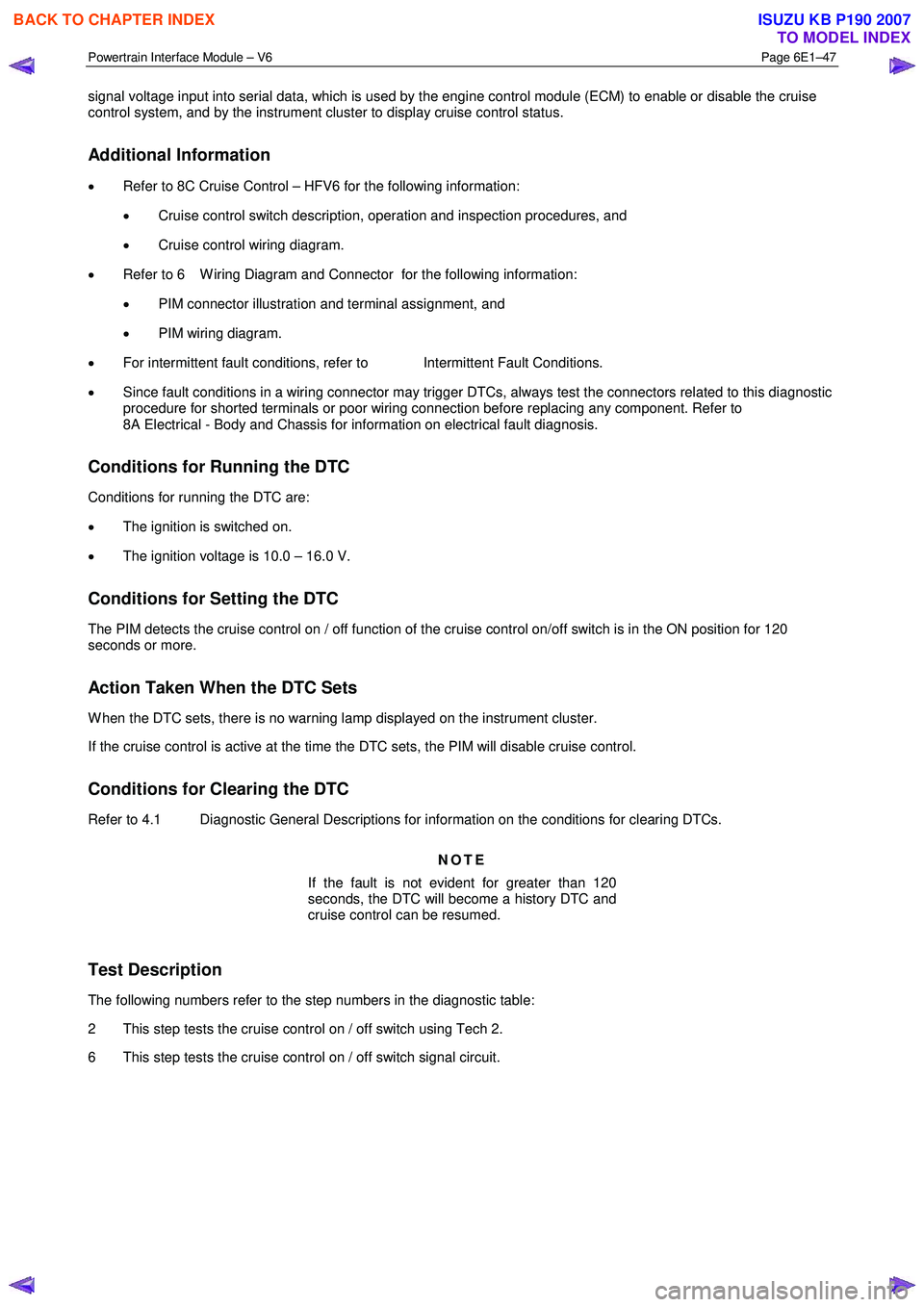
Powertrain Interface Module – V6 Page 6E1–47
signal voltage input into serial data, which is used by the engine control module (ECM) to enable or disable the cruise
control system, and by the instrument cluster to display cruise control status.
Additional Information
• Refer to 8C Cruise Control – HFV6 for the following information:
• Cruise control switch description, operation and inspection procedures, and
• Cruise control wiring diagram.
• Refer to 6 W iring Diagram and Connector for the following information:
• PIM connector illustration and terminal assignment, and
• PIM wiring diagram.
• For intermittent fault conditions, refer to Intermittent Fault Conditions.
• Since fault conditions in a wiring connector may trigger DTCs, always test the connectors related to this diagnostic
procedure for shorted terminals or poor wiring connection before replacing any component. Refer to
8A Electrical - Body and Chassis for information on electrical fault diagnosis.
Conditions for Running the DTC
Conditions for running the DTC are:
• The ignition is switched on.
• The ignition voltage is 10.0 – 16.0 V.
Conditions for Setting the DTC
The PIM detects the cruise control on / off function of the cruise control on/off switch is in the ON position for 120
seconds or more.
Action Taken When the DTC Sets
W hen the DTC sets, there is no warning lamp displayed on the instrument cluster.
If the cruise control is active at the time the DTC sets, the PIM will disable cruise control.
Conditions for Clearing the DTC
Refer to 4.1 Diagnostic General Descriptions for information on the conditions for clearing DTCs.
NOTE
If the fault is not evident for greater than 120
seconds, the DTC will become a history DTC and
cruise control can be resumed.
Test Description
The following numbers refer to the step numbers in the diagnostic table:
2 This step tests the cruise control on / off switch using Tech 2.
6 This step tests the cruise control on / off switch signal circuit.
BACK TO CHAPTER INDEX
TO MODEL INDEX
ISUZU KB P190 2007
Page 3711 of 6020
Powertrain Interface Module – V6 Page 6E1–50
• To assist diagnosis, refer to 6 W iring Diagram and Connector Chart for the system wiring diagram and
connector charts in this section.
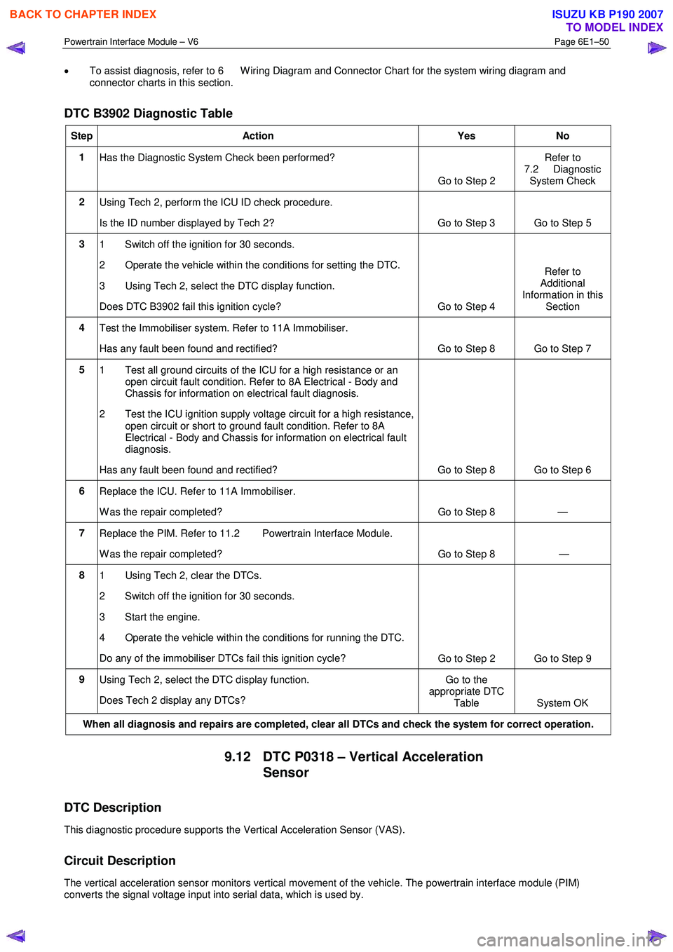
DTC B3902 Diagnostic Table
Step Action Yes No
1
Has the Diagnostic System Check been performed?
Go to Step 2 Refer to
7.2 Diagnostic System Check
2 Using Tech 2, perform the ICU ID check procedure.
Is the ID number displayed by Tech 2? Go to Step 3
Go to Step 5
3 1 Switch off the ignition for 30 seconds.
2 Operate the vehicle within the conditions for setting the DTC.
3 Using Tech 2, select the DTC display function.
Does DTC B3902 fail this ignition cycle? Go to Step 4 Refer to
Additional
Information in this Section
4 Test the Immobiliser system. Refer to 11A Immobiliser.
Has any fault been found and rectified? Go to Step 8 Go to Step 7
5 1 Test all ground circuits of the ICU for a high resistance or an
open circuit fault condition. Refer to 8A Electrical - Body and
Chassis for information on electrical fault diagnosis.
2 Test the ICU ignition supply voltage circuit for a high resistance, open circuit or short to ground fault condition. Refer to 8A
Electrical - Body and Chassis for information on electrical fault
diagnosis.
Has any fault been found and rectified? Go to Step 8 Go to Step 6
6 Replace the ICU. Refer to 11A Immobiliser.
W as the repair completed? Go to Step 8 —
7 Replace the PIM. Refer to 11.2 Powertrain Interface Module.
W as the repair completed? Go to Step 8 —
8 1 Using Tech 2, clear the DTCs.
2 Switch off the ignition for 30 seconds.
3 Start the engine.
4 Operate the vehicle within the conditions for running the DTC.
Do any of the immobiliser DTCs fail this ignition cycle? Go to Step 2 Go to Step 9
9
Using Tech 2, select the DTC display function.
Does Tech 2 display any DTCs? Go to the
appropriate DTC Table System OK
When all diagnosis and repairs are completed, clear all DTCs and check the system for correct operation.
9.12 DTC P0318 – Vertical Acceleration
Sensor
DTC Description
This diagnostic procedure supports the Vertical Acceleration Sensor (VAS).
Circuit Description
The vertical acceleration sensor monitors vertical movement of the vehicle. The powertrain interface module (PIM)
converts the signal voltage input into serial data, which is used by.
BACK TO CHAPTER INDEX
TO MODEL INDEX
ISUZU KB P190 2007