2007 ISUZU KB P190 CIRCUIT DIAGRAM
[x] Cancel search: CIRCUIT DIAGRAMPage 3433 of 6020
Engine Management – V6 – Diagnostics Page 6C1-2–155
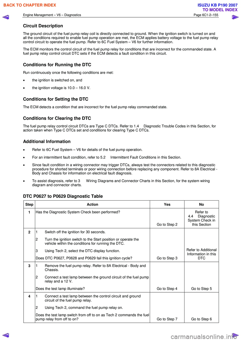
Circuit Description
The ground circuit of the fuel pump relay coil is directly connected to ground. W hen the ignition switch is turned on and
all the conditions required to enable fuel pump operation are met, the ECM applies battery voltage to the fuel pump relay
control circuit to operate the fuel pump. Refer to 6C Fuel System – V6 for further information.
The ECM monitors the control circuit of the fuel pump relay for conditions that are incorrect for the commanded state. A
fuel pump relay control circuit DTC sets if the ECM detects a fault condition in this circuit.
Conditions for Running the DTC
Run continuously once the following conditions are met:
• the ignition is switched on, and
• the ignition voltage is 10.0 – 16.0 V.
Conditions for Setting the DTC
The ECM detects a condition that are incorrect for the fuel pump relay commanded state.
Conditions for Clearing the DTC
The fuel pump relay control circuit DTCs are Type C DTCs. Refer to 1.4 Diagnostic Trouble Codes in this Section, for
action taken when Type C DTCs set and conditions for clearing Type C DTCs.
Additional Information
• Refer to 6C Fuel System – V6 for details of the fuel pump operation.
• For an intermittent fault condition, refer to 5.2 Intermittent Fault Conditions in this Section.
• Since fault condition in a wiring connector may trigger DTCs, always test the connectors related to this diagnostic
procedure for shorted terminals or poor wiring connection before replacing any component. Refer to 8A Electrical -
Body and Chassis for information on electrical fault diagnosis.
• To assist diagnosis, refer to 3 W iring Diagrams and Connector Charts in this Section, for the system wiring
diagram and connector charts.
DTC P0627 to P0629 Diagnostic Table
Step Action Yes No
1 Has the Diagnostic System Check been performed?
Go to Step 2 Refer to
4.4 Diagnostic
System Check in this Section
2 1 Switch off the ignition for 30 seconds.
2 Turn the ignition switch to the Start position or operate the vehicle within the conditions for running the DTC.
3 Using Tech 2, select the DTC display function.
Does DTC P0627, P0628 and P0629 fail this ignition cycle? Go to Step 3 Refer to Additional
Information in this DTC
3 1 Remove the fuel pump relay. Refer to 8A Electrical - Body and
Chassis.
2 Connect a test lamp between the ground circuit of the fuel pump relay and a 12 V.
Does the test lamp illuminate? Go to Step 4 Go to Step 5
4 1 Connect a test lamp between the control circuit and ground
circuit of the fuel pump relay.
2 Using Tech 2, command the fuel pump relay on.
Does the test lamp switch from off to on as Tech 2 commands the fuel
pump relay from off to on? Go to Step 7 Go to Step 6
BACK TO CHAPTER INDEX
TO MODEL INDEX
ISUZU KB P190 2007
Page 3435 of 6020
Engine Management – V6 – Diagnostics Page 6C1-2–157
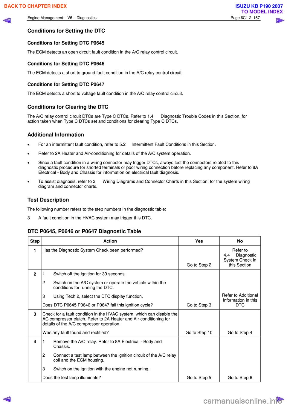
Conditions for Setting the DTC
Conditions for Setting DTC P0645
The ECM detects an open circuit fault condition in the A/C relay control circuit.
Conditions for Setting DTC P0646
The ECM detects a short to ground fault condition in the A/C relay control circuit.
Conditions for Setting DTC P0647
The ECM detects a short to voltage fault condition in the A/C relay control circuit.
Conditions for Clearing the DTC
The A/C relay control circuit DTCs are Type C DTCs. Refer to 1.4 Diagnostic Trouble Codes in this Section, for
action taken when Type C DTCs set and conditions for clearing Type C DTCs.
Additional Information
• For an intermittent fault condition, refer to 5.2 Intermittent Fault Conditions in this Section.
• Refer to 2A Heater and Air-conditioning for details of the A/C system operation.
• Since a fault condition in a wiring connector may trigger DTCs, always test the connectors related to this
diagnostic procedure for shorted terminals or poor wiring connection before replacing any component. Refer to 8A
Electrical - Body and Chassis for information on electrical fault diagnosis.
• To assist diagnosis, refer to 3 W iring Diagrams and Connector Charts in this Section, for the system wiring
diagram and connector charts.
Test Description
The following number refers to the step numbers in the diagnostic table:
3 A fault condition in the HVAC system may trigger this DTC.
DTC P0645, P0646 or P0647 Diagnostic Table
Step Action Yes No
1 Has the Diagnostic System Check been performed?
Go to Step 2 Refer to
4.4 Diagnostic
System Check in this Section
2 1 Switch off the ignition for 30 seconds.
2 Switch on the A/C system or operate the vehicle within the conditions for running the DTC.
3 Using Tech 2, select the DTC display function.
Does DTC P0645 P0646 or P0647 fail this ignition cycle? Go to Step 3 Refer to Additional
Information in this DTC
3 Check for a fault condition in the HVAC system, which can disable the
AC compressor clutch. Refer to 2A Heater and Air-conditioning for
details of the A/C compressor operation.
W as any fault found and rectified? Go to Step 10 Go to Step 4
4 1 Remove the A/C relay. Refer to 8A Electrical - Body and
Chassis.
2 Connect a test lamp between the ignition circuit of the A/C relay coil and the ECM housing.
3 Switch on the ignition with the engine not running.
Does the test lamp illuminate? Go to Step 5 Go to Step 6
BACK TO CHAPTER INDEX
TO MODEL INDEX
ISUZU KB P190 2007
Page 3437 of 6020
Engine Management – V6 – Diagnostics Page 6C1-2–159
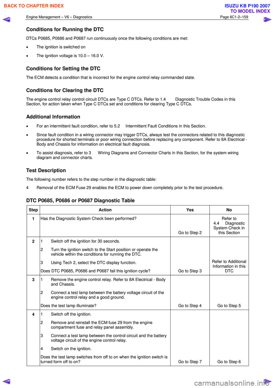
Conditions for Running the DTC
DTCs P0685, P0686 and P0687 run continuously once the following conditions are met:
• The ignition is switched on
• The ignition voltage is 10.0 – 16.0 V.
Conditions for Setting the DTC
The ECM detects a condition that is incorrect for the engine control relay commanded state.
Conditions for Clearing the DTC
The engine control relay control circuit DTCs are Type C DTCs. Refer to 1.4 Diagnostic Trouble Codes in this
Section, for action taken when Type C DTCs set and conditions for clearing Type C DTCs.
Additional Information
• For an intermittent fault condition, refer to 5.2 Intermittent Fault Conditions in this Section.
• Since fault condition in a wiring connector may trigger DTCs, always test the connectors related to this diagnostic
procedure for shorted terminals or poor wiring connection before replacing any component. Refer to 8A Electrical -
Body and Chassis for information on electrical fault diagnosis.
• To assist diagnosis, refer to 3 W iring Diagrams and Connector Charts in this Section, for the system wiring
diagram and connector charts.
Test Description
The following number refers to the step number in the diagnostic table:
4 Removal of the ECM Fuse 29 enables the ECM to power down completely prior to the test procedure.
DTC P0685, P0686 or P0687 Diagnostic Table
Step Action Yes No
1 Has the Diagnostic System Check been performed?
Go to Step 2 Refer to
4.4 Diagnostic
System Check in this Section
2 1 Switch off the ignition for 30 seconds.
2 Turn the ignition switch to the Start position or operate the vehicle within the conditions for running the DTC.
3 Using Tech 2, select the DTC display function.
Does DTC P0685, P0686 and P0687 fail this ignition cycle? Go to Step 3 Refer to Additional
Information in this DTC
3 1 Remove the engine control relay. Refer to 8A Electrical - Body
and Chassis.
2 Connect a test lamp between the battery voltage circuit of the engine control relay and a good ground.
Does the test lamp illuminate? Go to Step 4 Go to Step 5
4 1 Switch off the ignition.
2 Remove and reinstall the ECM fuse 29 from the engine compartment fuse and relay panel assembly.
3 Connect a test lamp between the control circuit and the battery voltage circuit of the engine control relay.
4 Switch on the ignition.
Does the test lamp switches from off to on when the ignition switch is
turned form off to on? Go to Step 7 Go to Step 6
BACK TO CHAPTER INDEX
TO MODEL INDEX
ISUZU KB P190 2007
Page 3439 of 6020
Engine Management – V6 – Diagnostics Page 6C1-2–161
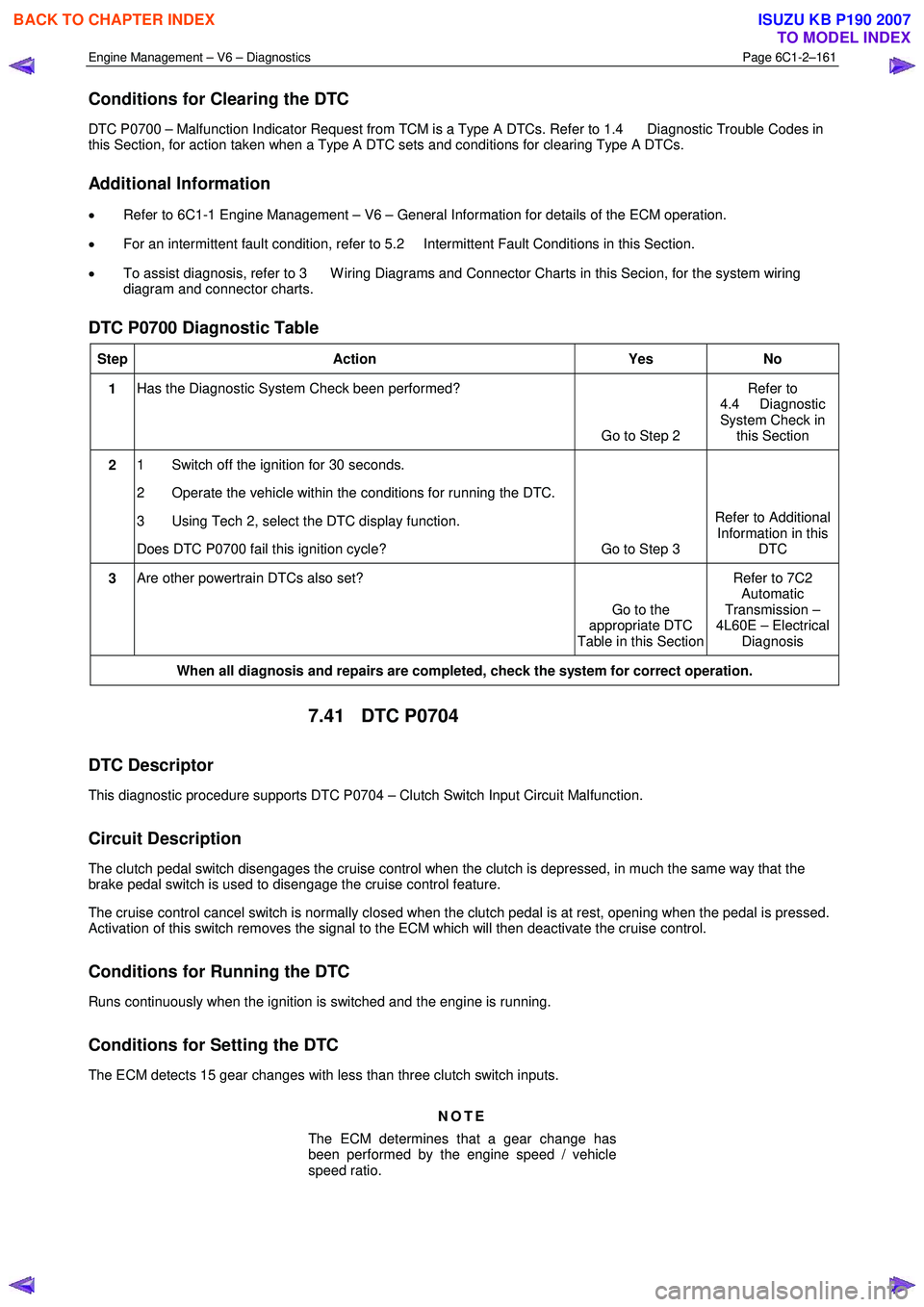
Conditions for Clearing the DTC
DTC P0700 – Malfunction Indicator Request from TCM is a Type A DTCs. Refer to 1.4 Diagnostic Trouble Codes in
this Section, for action taken when a Type A DTC sets and conditions for clearing Type A DTCs.
Additional Information
• Refer to 6C1-1 Engine Management – V6 – General Information for details of the ECM operation.
• For an intermittent fault condition, refer to 5.2 Intermittent Fault Conditions in this Section.
• To assist diagnosis, refer to 3 W iring Diagrams and Connector Charts in this Secion, for the system wiring
diagram and connector charts.
DTC P0700 Diagnostic Table
Step Action Yes No
1 Has the Diagnostic System Check been performed?
Go to Step 2 Refer to
4.4 Diagnostic
System Check in this Section
2 1 Switch off the ignition for 30 seconds.
2 Operate the vehicle within the conditions for running the DTC.
3 Using Tech 2, select the DTC display function.
Does DTC P0700 fail this ignition cycle? Go to Step 3 Refer to Additional
Information in this DTC
3 Are other powertrain DTCs also set?
Go to the
appropriate DTC
Table in this Section Refer to 7C2
Automatic
Transmission –
4L60E – Electrical Diagnosis
When all diagnosis and repairs are completed, check the system for correct operation.
7.41 DTC P0704
DTC Descriptor
This diagnostic procedure supports DTC P0704 – Clutch Switch Input Circuit Malfunction.
Circuit Description
The clutch pedal switch disengages the cruise control when the clutch is depressed, in much the same way that the
brake pedal switch is used to disengage the cruise control feature.
The cruise control cancel switch is normally closed when the clutch pedal is at rest, opening when the pedal is pressed.
Activation of this switch removes the signal to the ECM which will then deactivate the cruise control.
Conditions for Running the DTC
Runs continuously when the ignition is switched and the engine is running.
Conditions for Setting the DTC
The ECM detects 15 gear changes with less than three clutch switch inputs.
NOTE
The ECM determines that a gear change has
been performed by the engine speed / vehicle
speed ratio.
BACK TO CHAPTER INDEX
TO MODEL INDEX
ISUZU KB P190 2007
Page 3440 of 6020
Engine Management – V6 – Diagnostics Page 6C1-2–162
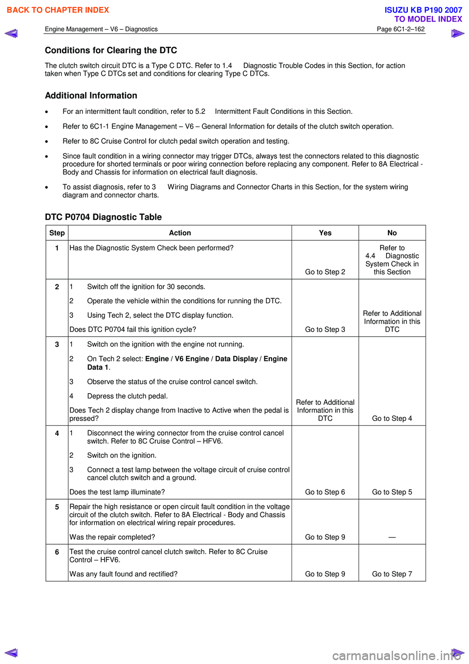
Conditions for Clearing the DTC
The clutch switch circuit DTC is a Type C DTC. Refer to 1.4 Diagnostic Trouble Codes in this Section, for action
taken when Type C DTCs set and conditions for clearing Type C DTCs.
Additional Information
• For an intermittent fault condition, refer to 5.2 Intermittent Fault Conditions in this Section.
• Refer to 6C1-1 Engine Management – V6 – General Information for details of the clutch switch operation.
• Refer to 8C Cruise Control for clutch pedal switch operation and testing.
• Since fault condition in a wiring connector may trigger DTCs, always test the connectors related to this diagnostic
procedure for shorted terminals or poor wiring connection before replacing any component. Refer to 8A Electrical -
Body and Chassis for information on electrical fault diagnosis.
• To assist diagnosis, refer to 3 W iring Diagrams and Connector Charts in this Section, for the system wiring
diagram and connector charts.
DTC P0704 Diagnostic Table
Step Action Yes No
1 Has the Diagnostic System Check been performed?
Go to Step 2 Refer to
4.4 Diagnostic
System Check in this Section
2 1 Switch off the ignition for 30 seconds.
2 Operate the vehicle within the conditions for running the DTC.
3 Using Tech 2, select the DTC display function.
Does DTC P0704 fail this ignition cycle? Go to Step 3 Refer to Additional
Information in this DTC
3 1 Switch on the ignition with the engine not running.
2 On Tech 2 select: Engine / V6 Engine / Data Display / Engine
Data 1 .
3 Observe the status of the cruise control cancel switch.
4 Depress the clutch pedal.
Does Tech 2 display change from Inactive to Active when the pedal is
pressed? Refer to Additional
Information in this DTC Go to Step 4
4 1 Disconnect the wiring connector from the cruise control cancel
switch. Refer to 8C Cruise Control – HFV6.
2 Switch on the ignition.
3 Connect a test lamp between the voltage circuit of cruise control cancel clutch switch and a ground.
Does the test lamp illuminate? Go to Step 6 Go to Step 5
5 Repair the high resistance or open circuit fault condition in the voltage
circuit of the clutch switch. Refer to 8A Electrical - Body and Chassis
for information on electrical wiring repair procedures.
W as the repair completed? Go to Step 9 —
6 Test the cruise control cancel clutch switch. Refer to 8C Cruise
Control – HFV6.
W as any fault found and rectified? Go to Step 9 Go to Step 7
BACK TO CHAPTER INDEX
TO MODEL INDEX
ISUZU KB P190 2007
Page 3442 of 6020
Engine Management – V6 – Diagnostics Page 6C1-2–164
• Since fault condition in a wiring connector may trigger DTCs, always test the connectors related to this diagnostic
procedure for shorted terminals or poor wiring connection before replacing any component. Refer to 8A Electrical -
Body and Chassis for information on electrical fault diagnosis.
• To assist diagnosis, refer to 3 W iring Diagrams and Connector Charts in this Section, for the system wiring
diagram and connector charts.
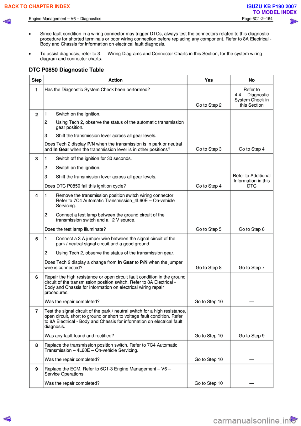
DTC P0850 Diagnostic Table
Step Action Yes No
1 Has the Diagnostic System Check been performed?
Go to Step 2 Refer to
4.4 Diagnostic
System Check in this Section
2 1 Switch on the ignition.
2 Using Tech 2, observe the status of the automatic transmission gear position.
3 Shift the transmission lever across all gear levels.
Does Tech 2 display P/N when the transmission is in park or neutral
and In Gear when the transmission lever is in other positions? Go to Step 3 Go to Step 4
3
1 Switch off the ignition for 30 seconds.
2 Switch on the ignition.
3 Shift the transmission lever across all gear levels.
Does DTC P0850 fail this ignition cycle? Go to Step 4 Refer to Additional
Information in this DTC
4 1 Remove the transmission position switch wiring connector.
Refer to 7C4 Automatic Transmission_4L60E – On-vehicle
Servicing.
2 Connect a test lamp between the ground circuit of the transmission switch and a 12 V source.
Does the test lamp illuminate? Go to Step 5 Go to Step 6
5 1 Connect a 3 A jumper wire between the signal circuit of the
park / neutral signal circuit and a good ground.
2 Using Tech 2, observe the status of the transmission gear.
Does Tech 2 display a change from In Gear to P/N when the jumper
wire is connected? Go to Step 8 Go to Step 7
6 Repair the high resistance or open circuit fault condition in the ground
circuit of the transmission position switch. Refer to 8A Electrical -
Body and Chassis for information on electrical wiring repair
procedures.
W as the repair completed? Go to Step 10 —
7 Test the signal circuit of the park / neutral switch for a high resistance,
open circuit, short to ground or short to voltage fault condition. Refer
to 8A Electrical - Body and Chassis for information on electrical fault
diagnosis.
W as any fault found and rectified? Go to Step 10 Go to Step 9
8 Replace the transmission position switch. Refer to 7C4 Automatic
Transmission – 4L60E – On-vehicle Servicing.
W as the repair completed? Go to Step 10 —
9 Replace the ECM. Refer to 6C1-3 Engine Management – V6 –
Service Operations.
W as the repair completed? Go to Step 10 —
BACK TO CHAPTER INDEX
TO MODEL INDEX
ISUZU KB P190 2007
Page 3443 of 6020
Engine Management – V6 – Diagnostics Page 6C1-2–165
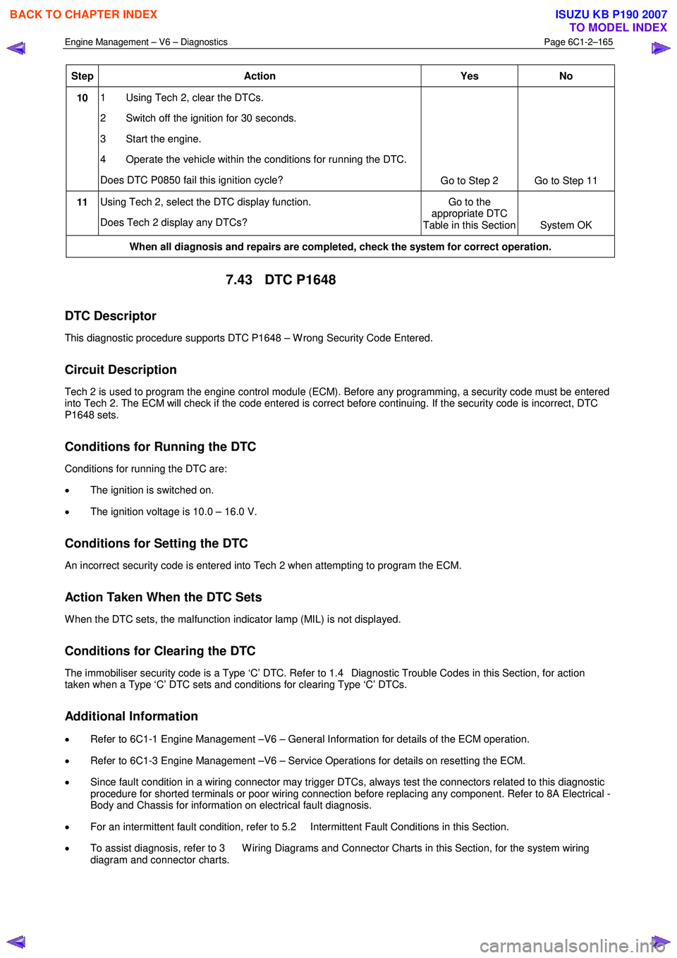
Step Action Yes
No
10 1 Using Tech 2, clear the DTCs.
2 Switch off the ignition for 30 seconds.
3 Start the engine.
4 Operate the vehicle within the conditions for running the DTC.
Does DTC P0850 fail this ignition cycle? Go to Step 2 Go to Step 11
11 Using Tech 2, select the DTC display function.
Does Tech 2 display any DTCs? Go to the
appropriate DTC
Table in this Section System OK
When all diagnosis and repairs are completed, check the system for correct operation.
7.43 DTC P1648
DTC Descriptor
This diagnostic procedure supports DTC P1648 – W rong Security Code Entered.
Circuit Description
Tech 2 is used to program the engine control module (ECM). Before any programming, a security code must be entered
into Tech 2. The ECM will check if the code entered is correct before continuing. If the security code is incorrect, DTC
P1648 sets.
Conditions for Running the DTC
Conditions for running the DTC are:
• The ignition is switched on.
• The ignition voltage is 10.0 – 16.0 V.
Conditions for Setting the DTC
An incorrect security code is entered into Tech 2 when attempting to program the ECM.
Action Taken When the DTC Sets
W hen the DTC sets, the malfunction indicator lamp (MIL) is not displayed.
Conditions for Clearing the DTC
The immobiliser security code is a Type ‘C’ DTC. Refer to 1.4 Diagnostic Trouble Codes in this Section, for action
taken when a Type ‘C’ DTC sets and conditions for clearing Type ‘C’ DTCs.
Additional Information
• Refer to 6C1-1 Engine Management –V6 – General Information for details of the ECM operation.
• Refer to 6C1-3 Engine Management –V6 – Service Operations for details on resetting the ECM.
• Since fault condition in a wiring connector may trigger DTCs, always test the connectors related to this diagnostic
procedure for shorted terminals or poor wiring connection before replacing any component. Refer to 8A Electrical -
Body and Chassis for information on electrical fault diagnosis.
• For an intermittent fault condition, refer to 5.2 Intermittent Fault Conditions in this Section.
• To assist diagnosis, refer to 3 W iring Diagrams and Connector Charts in this Section, for the system wiring
diagram and connector charts.
BACK TO CHAPTER INDEX
TO MODEL INDEX
ISUZU KB P190 2007
Page 3446 of 6020
Engine Management – V6 – Diagnostics Page 6C1-2–168
• To assist diagnosis, refer to 3 W iring Diagrams and Connector Charts in this Section, for the system wiring
diagram and connector charts.
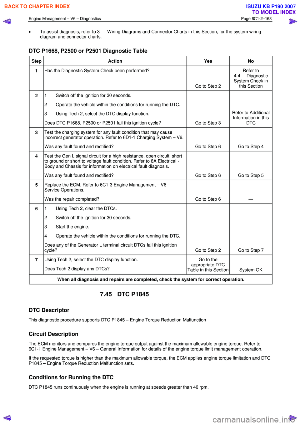
DTC P1668, P2500 or P2501 Diagnostic Table
Step Action Yes No
1 Has the Diagnostic System Check been performed?
Go to Step 2 Refer to
4.4 Diagnostic
System Check in this Section
2 1 Switch off the ignition for 30 seconds.
2 Operate the vehicle within the conditions for running the DTC.
3 Using Tech 2, select the DTC display function.
Does DTC P1668, P2500 or P2501 fail this ignition cycle? Go to Step 3 Refer to Additional
Information in this DTC
3 Test the charging system for any fault condition that may cause
incorrect generator operation. Refer to 6D1-1 Charging System – V6.
W as any fault found and rectified? Go to Step 6 Go to Step 4
4 Test the Gen L signal circuit for a high resistance, open circuit, short
to ground or short to voltage fault condition. Refer to 8A Electrical -
Body and Chassis for information on electrical fault diagnosis.
W as any fault found and rectified? Go to Step 6 Go to Step 5
5 Replace the ECM. Refer to 6C1-3 Engine Management – V6 –
Service Operations.
W as the repair completed? Go to Step 6 —
6 1 Using Tech 2, clear the DTCs.
2 Switch off the ignition for 30 seconds.
3 Start the engine.
4 Operate the vehicle within the conditions for running the DTC.
Does any of the Generator L terminal circuit DTCs fail this ignition
cycle? Go to Step 2 Go to Step 7
7 Using Tech 2, select the DTC display function.
Does Tech 2 display any DTCs? Go to the
appropriate DTC
Table in this Section System OK
When all diagnosis and repairs are completed, check the system for correct operation.
7.45 DTC P1845
DTC Descriptor
This diagnostic procedure supports DTC P1845 – Engine Torque Reduction Malfunction
Circuit Description
The ECM monitors and compares the engine torque output against the maximum allowable engine torque. Refer to
6C1-1 Engine Management – V6 – General Information for details of the engine torque limit management operation.
If the requested torque is higher than the maximum allowable torque, the ECM applies engine torque limitation and DTC
P1845 – Engine Torque Reduction Malfunction sets.
Conditions for Running the DTC
DTC P1845 runs continuously when the engine is running at speeds greater than 40 rpm.
BACK TO CHAPTER INDEX
TO MODEL INDEX
ISUZU KB P190 2007