2007 ISUZU KB P190 sensor
[x] Cancel search: sensorPage 3889 of 6020
Automatic Transmission – 4L60E – Electrical Diagnosis Page 7C2–103
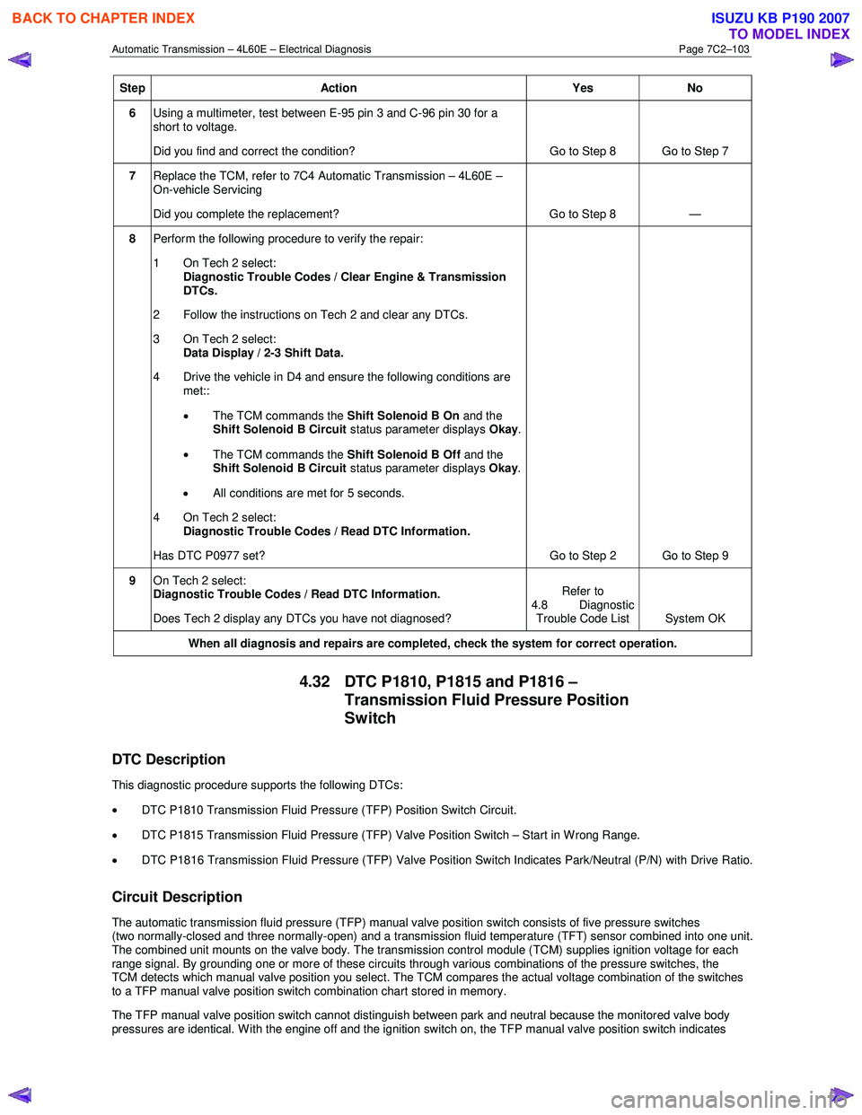
Step Action Yes No
6 Using a multimeter, test between E-95 pin 3 and C-96 pin 30 for a
short to voltage.
Did you find and correct the condition? Go to Step 8 Go to Step 7
7 Replace the TCM, refer to 7C4 Automatic Transmission – 4L60E –
On-vehicle Servicing
Did you complete the replacement? Go to Step 8 —
8 Perform the following procedure to verify the repair:
1 On Tech 2 select: Diagnostic Trouble Codes / Clear Engine & Transmission
DTCs.
2 Follow the instructions on Tech 2 and clear any DTCs.
3 On Tech 2 select: Data Display / 2-3 Shift Data.
4 Drive the vehicle in D4 and ensure the following conditions are met::
• The TCM commands the Shift Solenoid B On and the
Shift Solenoid B Circuit status parameter displays Okay.
• The TCM commands the Shift Solenoid B Off and the
Shift Solenoid B Circuit status parameter displays Okay.
• All conditions are met for 5 seconds.
4 On Tech 2 select:
Diagnostic Trouble Codes / Read DTC Information.
Has DTC P0977 set? Go to Step 2 Go to Step 9
9 On Tech 2 select:
Diagnostic Trouble Codes / Read DTC Information.
Does Tech 2 display any DTCs you have not diagnosed? Refer to
4.8 Diagnostic Trouble Code List System OK
When all diagnosis and repairs are completed, check the
system for correct operation.
4.32 DTC P1810, P1815 and P1816 –
Transmission Fluid Pressure Position
Switch
DTC Description
This diagnostic procedure supports the following DTCs:
• DTC P1810 Transmission Fluid Pressure (TFP) Position Switch Circuit.
• DTC P1815 Transmission Fluid Pressure (TFP) Valve Position Switch – Start in W rong Range.
• DTC P1816 Transmission Fluid Pressure (TFP) Valve Position Switch Indicates Park/Neutral (P/N) with Drive Ratio.
Circuit Description
The automatic transmission fluid pressure (TFP) manual valve position switch consists of five pressure switches
(two normally-closed and three normally-open) and a transmission fluid temperature (TFT) sensor combined into one unit.
The combined unit mounts on the valve body. The transmission control module (TCM) supplies ignition voltage for each
range signal. By grounding one or more of these circuits through various combinations of the pressure switches, the
TCM detects which manual valve position you select. The TCM compares the actual voltage combination of the switches
to a TFP manual valve position switch combination chart stored in memory.
The TFP manual valve position switch cannot distinguish between park and neutral because the monitored valve body
pressures are identical. W ith the engine off and the ignition switch on, the TFP manual valve position switch indicates
BACK TO CHAPTER INDEX
TO MODEL INDEX
ISUZU KB P190 2007
Page 3910 of 6020
Automatic Transmission – 4L60E – Electrical Diagnosis Page 7C2–124
5 Electrical Specifications
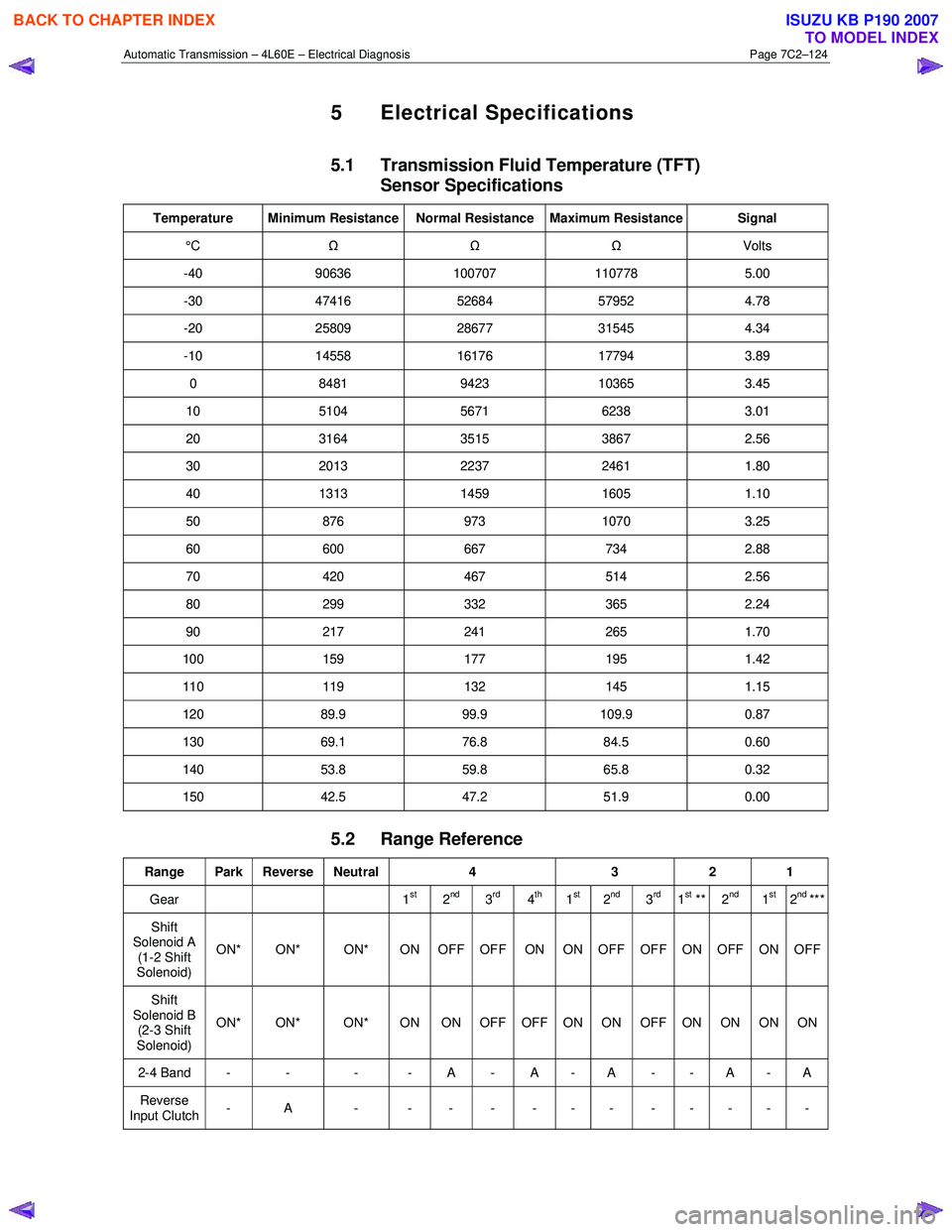
5.1 Transmission Fluid Temperature (TFT)
Sensor Specifications
Temperature Minimum Resistance Normal Resistance Maximum Resistance Signal
°C Ω Ω Ω Volts
-40 90636 100707 110778 5.00
-30 47416 52684 57952 4.78
-20 25809 28677 31545 4.34
-10 14558 16176 17794 3.89
0 8481 9423 10365 3.45
10 5104 5671 6238 3.01
20 3164 3515 3867 2.56
30 2013 2237 2461 1.80
40 1313 1459 1605 1.10
50 876 973 1070 3.25
60 600 667 734 2.88
70 420 467 514 2.56
80 299 332 365 2.24
90 217 241 265 1.70
100 159 177 195 1.42
110 119 132 145 1.15
120 89.9 99.9 109.9 0.87
130 69.1 76.8 84.5 0.60
140 53.8 59.8 65.8 0.32
150 42.5 47.2 51.9 0.00
5.2 Range Reference
Range Park Reverse Neutral 4 3 2 1
Gear 1st 2nd3rd4th1st2nd3rd1st ** 2nd 1st2nd ***
Shift
Solenoid A (1-2 Shift
Solenoid) ON* ON* ON* ON OFF OFF ON ON OFF OFF ON OFF ON OFF
Shift
Solenoid B (2-3 Shift
Solenoid) ON* ON* ON* ON ON OFF OFF ON ON OFF ON ON ON ON
2-4 Band - - - - A - A - A - - A - A
Reverse
Input Clutch - A - - - - - - - - - - - -
BACK TO CHAPTER INDEX
TO MODEL INDEX
ISUZU KB P190 2007
Page 3912 of 6020
Automatic Transmission – 4L60E – Electrical Diagnosis Page 7C2–126
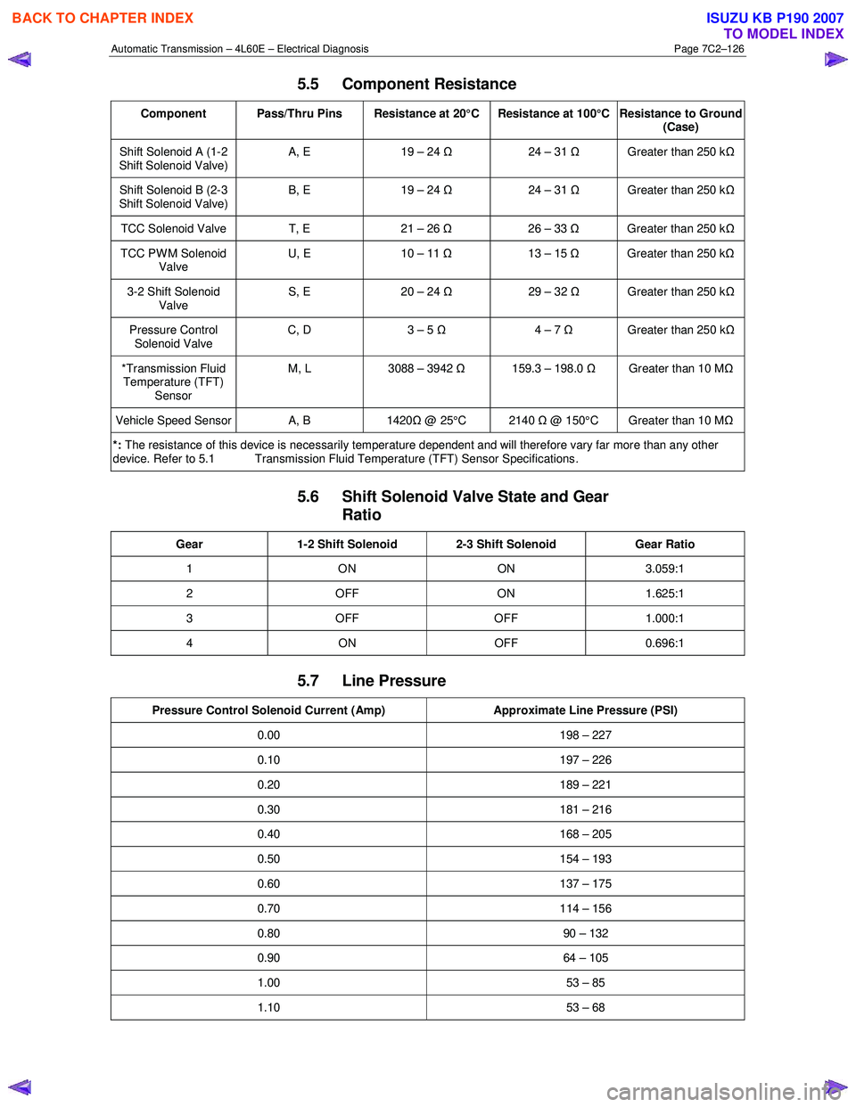
5.5 Component Resistance
Component Pass/Thru Pins Resistance at 20°C Resistance at 100°C Resistance to Ground
(Case)
Shift Solenoid A (1-2
Shift Solenoid Valve) A, E 19 – 24
Ω 24 – 31 Ω Greater than 250 k Ω
Shift Solenoid B (2-3
Shift Solenoid Valve) B, E 19 – 24
Ω 24 – 31 Ω Greater than 250 k Ω
TCC Solenoid Valve T, E 21 – 26 Ω 26 – 33 Ω Greater than 250 k Ω
TCC PWM Solenoid
Valve U, E
10 – 11 Ω 13 – 15 Ω Greater than 250 k Ω
3-2 Shift Solenoid
Valve S, E 20 – 24
Ω 29 – 32 Ω Greater than 250 k Ω
Pressure Control
Solenoid Valve C, D
3 – 5 Ω 4 – 7 Ω Greater than 250 k Ω
*Transmission Fluid
Temperature (TFT) Sensor M, L
3088 – 3942 Ω 159.3 – 198.0 Ω Greater than 10 M Ω
Vehicle Speed Sensor A, B 1420Ω @ 25°C 2140 Ω @ 150°C Greater than 10 M Ω
*: The resistance of this device is necessarily temperature dependent and will therefore vary far more than any other
device. Refer to 5.1 Transmission Fluid Temperature (TFT) Sensor Specifications .
5.6 Shift Solenoid Valve State and Gear
Ratio
Gear 1-2 Shift Solenoid 2-3 Shift Solenoid Gear Ratio
1 ON ON 3.059:1
2 OFF ON 1.625:1
3 OFF OFF 1.000:1
4 ON OFF 0.696:1
5.7 Line Pressure
Pressure Control Solenoid Current (Amp) Approximate Line Pressure (PSI)
0.00 198 – 227
0.10 197 – 226
0.20 189 – 221
0.30 181 – 216
0.40 168 – 205
0.50 154 – 193
0.60 137 – 175
0.70 114 – 156
0.80 90 – 132
0.90 64 – 105
1.00 53 – 85
1.10 53 – 68
BACK TO CHAPTER INDEX
TO MODEL INDEX
ISUZU KB P190 2007
Page 3914 of 6020
Automatic Transmission – 4L60E – On-vehicle Servicing Page 7C4–1
7C4
Automatic Transmission – 4L60E –
On-vehicle Servicing
ATTENTION
Before performing any service operation or other procedure described in this Section, refer to General Information Warnings, Cautions and Notes for correct workshop practices with regard to safety and/or property damage.
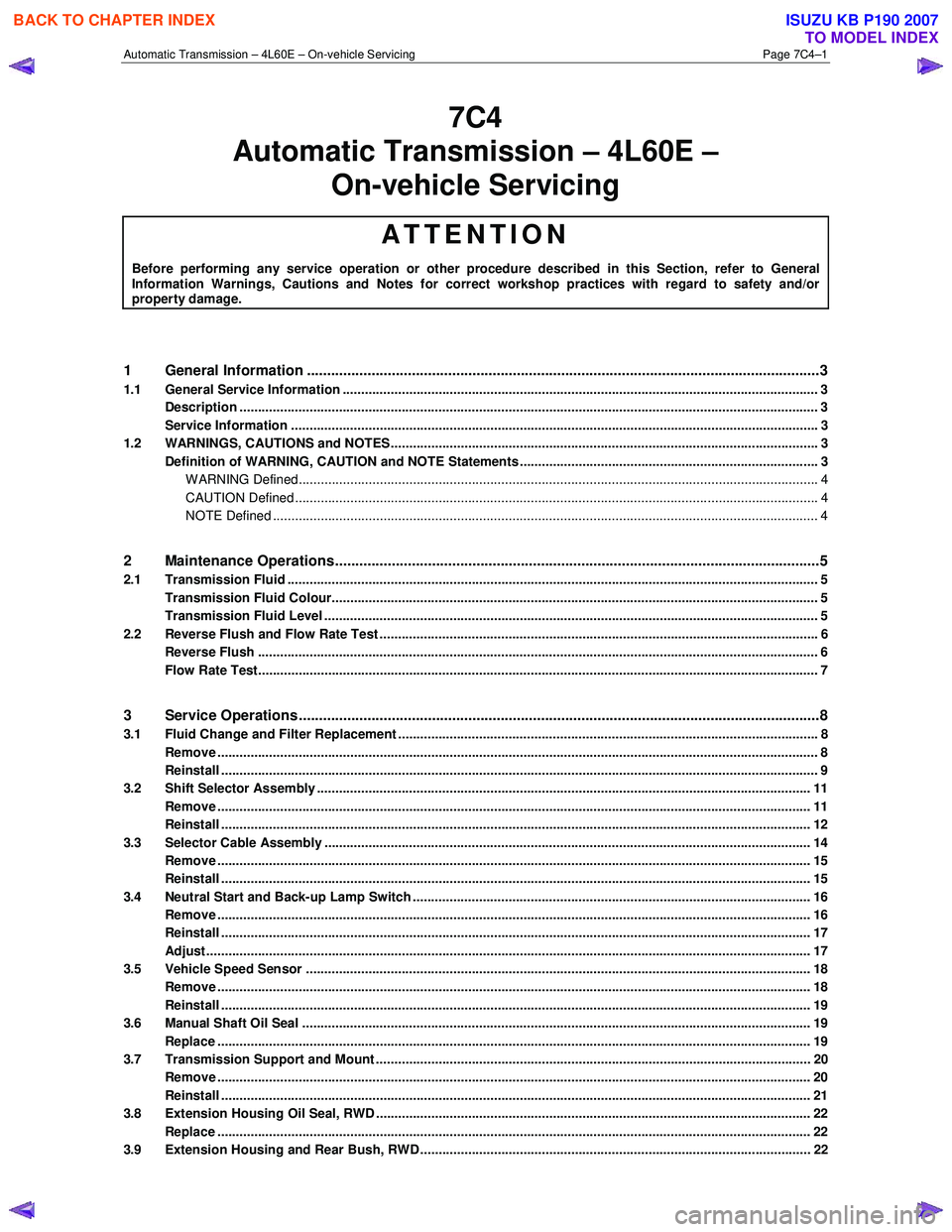
1 General Information ............................................................................................................ ...................3
1.1 General Service Information ................................................................................................................................. 3
Description ............................................................................................................................................................. 3
Service Information ............................................................................................................ ................................... 3
1.2 WARNINGS, CAUTIONS and NOTES................................................................................................... ................. 3
Definition of WARNING, CAUTION and NOTE Statements ............................................................................. .... 3
WARNING Defined............................................................................................................................................. 4
CAUTION Defined .............................................................................................................................................. 4
NOTE Defined .................................................................................................................................................... 4
2 Maintenance Operations......................................................................................................... ...............5
2.1 Transmission Fluid ................................................................................................................................................ 5
Transmission Fluid Colour...................................................................................................... .............................. 5
Transmission Fluid Level ...................................................................................................................................... 5
2.2 Reverse Flush and Flow Rate Test ............................................................................................... ........................ 6
Reverse Flush ........................................................................................................................................................ 6
Flow Rate Test........................................................................................................................................................ 7
3 Service Operations ............................................................................................................. ....................8
3.1 Fluid Change and Filter Replacement ............................................................................................ ...................... 8
Remove ................................................................................................................................................................... 8
Reinstall .................................................................................................................................................................. 9
3.2 Shift Selector Assembly ...................................................................................................................................... 11
Remove ................................................................................................................................................................. 11
Reinstall ................................................................................................................................................................ 12
3.3 Selector Cable Assembly .................................................................................................................................... 14
Remove ................................................................................................................................................................. 15
Reinstall ................................................................................................................................................................ 15
3.4 Neutral Start and Back-up Lamp Switch ............................................................................................................ 16
Remove ................................................................................................................................................................. 16
Reinstall ................................................................................................................................................................ 17
Adjust .................................................................................................................................................................... 17
3.5 Vehicle Speed Sensor ......................................................................................................................................... 18
Remove ................................................................................................................................................................. 18
Reinstall ................................................................................................................................................................ 19
3.6 Manual Shaft Oil Seal .......................................................................................................................................... 19
Replace ................................................................................................................................................................. 19
3.7 Transmission Support and Mount ................................................................................................. ..................... 20
Remove ................................................................................................................................................................. 20
Reinstall ................................................................................................................................................................ 21
3.8 Extension Housing Oil Seal, RWD ...................................................................................................................... 22
Replace ................................................................................................................................................................. 22
3.9 Extension Housing and Rear Bush, RWD ........................................................................................... ............... 22
BACK TO CHAPTER INDEX
TO MODEL INDEX
ISUZU KB P190 2007
Page 3931 of 6020
Automatic Transmission – 4L60E – On-vehicle Servicing Page 7C4–18
Ensure the four wheels are off the ground
before performing the starting test.
4 W ith the ignition switched to the ON position, check if the engine can only be started in the Park and Neutral shift selector positions and ensure the back-up lamps illuminate when Reverse is selected. A further minor adjustment
may be required to achieve this state.
NOTE
To gain access to the rear attaching screw (11) it
will be necessary to remove the connector.
5 After the switch has been adjusted, tighten the rear attaching screw (11) to the correct torque specification. Neutral start and back-up lamp switch
attaching screw torque specification .................. 25.0 Nm
6 Reinstall the connector and the CPA securing pin.
7 Remove the switch front attaching screw (1).
8 Install the heat shield (3) and tighten the attaching screws (1 and 2) to the correct torque specification.
Heat shield front attaching screw
torque specification ............................................ 25.0 Nm
Heat shield rear attaching screw torque specification ..............................................9.0 Nm
9 Lower the vehicle to the ground and re-check the operation of the neutral start and back-up lamp switch. The vehicle must start only with the shift selector in the Park or Neutral positions and the back-up lamps should only
illuminate when Reverse is selected.
3.5 Vehicle Speed Sensor
NOTE
For the speed sensor fitted to four wheel drive
vehicles (4WD), refer to 7D Transfer Case and
Adaptor Housing.
Remove
1 Raise the vehicle and support in a safe manner, refer
to 0A General Information for the location of support
points.
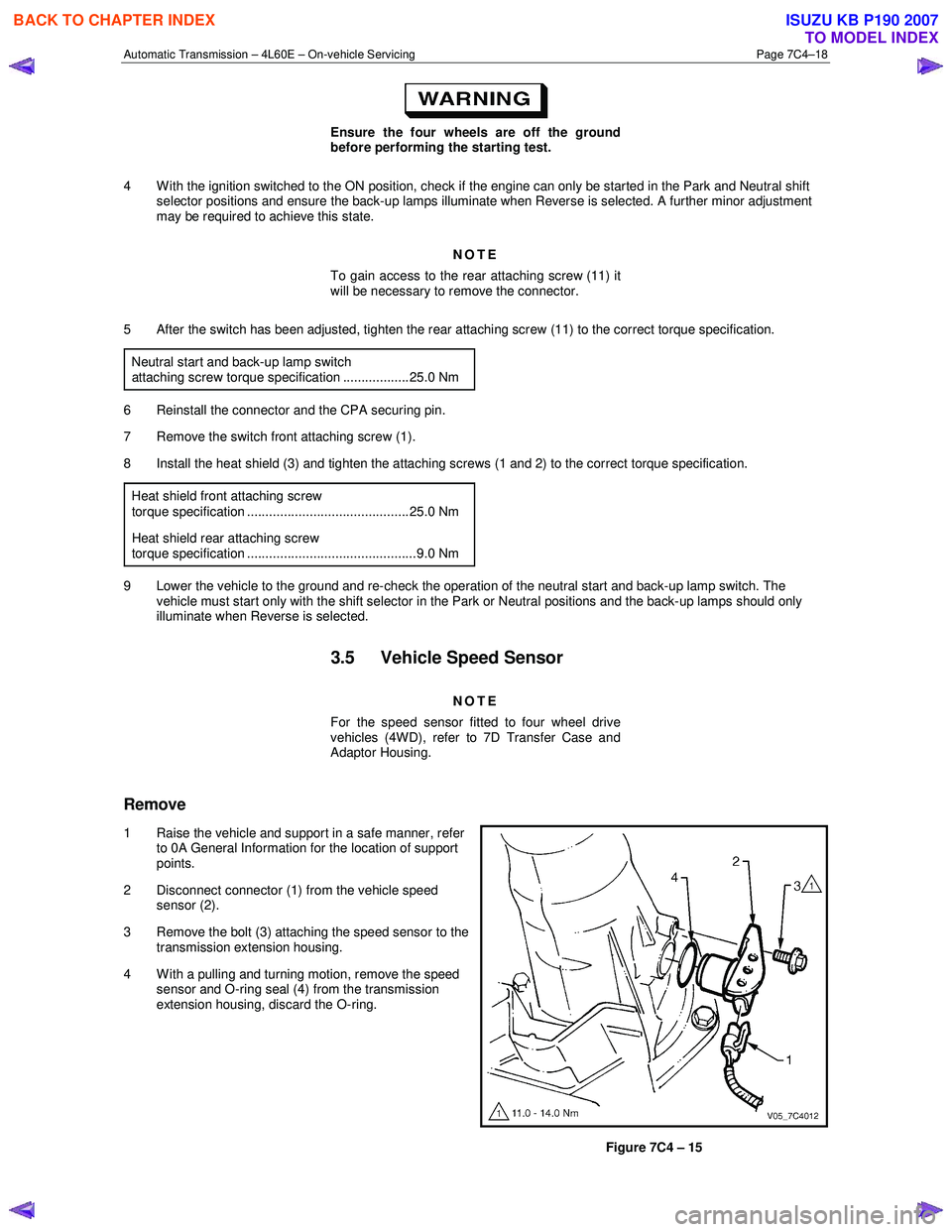
2 Disconnect connector (1) from the vehicle speed sensor (2).
3 Remove the bolt (3) attaching the speed sensor to the transmission extension housing.
4 With a pulling and turning motion, remove the speed sensor and O-ring seal (4) from the transmission
extension housing, discard the O-ring.
Figure 7C4 – 15
BACK TO CHAPTER INDEX
TO MODEL INDEX
ISUZU KB P190 2007
Page 3932 of 6020
Automatic Transmission – 4L60E – On-vehicle Servicing Page 7C4–19
Reinstall
1 Lubricate a new O-ring seal with petroleum jelly and install it to the vehicle speed sensor.
2 Install the speed sensor to the transmission extension housing.
3 Install the attaching bolt and tighten to the correct torque specification.
Vehicle speed sensor attaching bolt
torque specification ............................................ 12.0 Nm
4 Connect the connector to the speed sensor.
5 Lower the vehicle to the ground.
3.6 Manual Shaft Oil Seal
Replace
NOTE
This procedure requires the use of special tool
No. AU583.
1 Raise the vehicle and support in a safe manner, refer to 0A General Information for the location of support points.
2 Remove the neutral start and back-up lamp switch, refer to 3.4 Neutral Start and Back-up Lamp Switch.
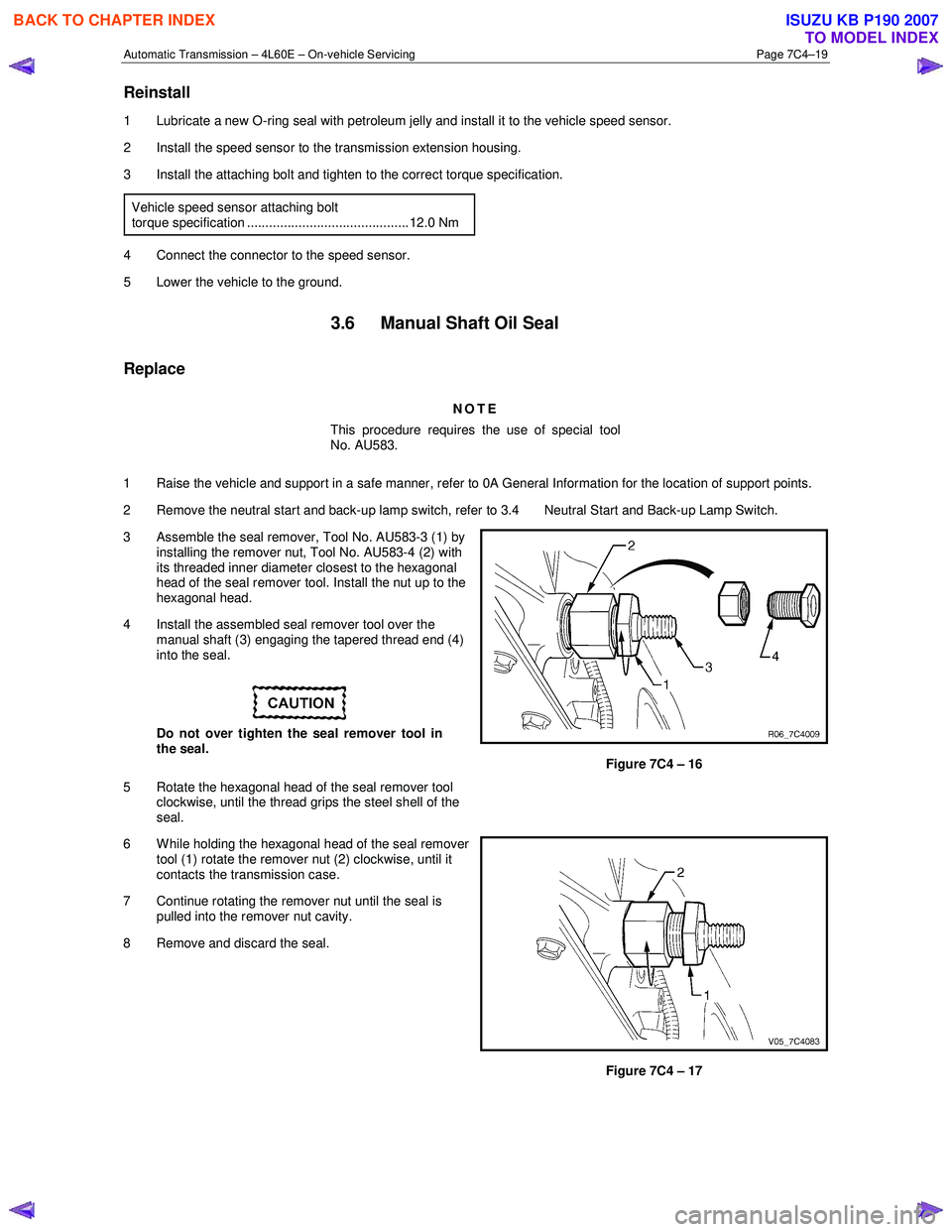
3 Assemble the seal remover, Tool No. AU583-3 (1) by installing the remover nut, Tool No. AU583-4 (2) with
its threaded inner diameter closest to the hexagonal
head of the seal remover tool. Install the nut up to the
hexagonal head.
4 Install the assembled seal remover tool over the manual shaft (3) engaging the tapered thread end (4)
into the seal.
Do not over tighten the seal remover tool in
the seal.
5 Rotate the hexagonal head of the seal remover tool clockwise, until the thread grips the steel shell of the
seal.
Figure 7C4 – 16
6 W hile holding the hexagonal head of the seal remover tool (1) rotate the remover nut (2) clockwise, until it
contacts the transmission case.
7 Continue rotating the remover nut until the seal is pulled into the remover nut cavity.
8 Remove and discard the seal.
Figure 7C4 – 17
BACK TO CHAPTER INDEX
TO MODEL INDEX
ISUZU KB P190 2007
Page 3935 of 6020
Automatic Transmission – 4L60E – On-vehicle Servicing Page 7C4–22
3.8 Extension Housing Oil Seal, RWD
Replace
1 Raise the vehicle and support in a safe manner, refer to 0A General Information for the location of support points.
2 Remove the rear propeller shaft, refer to 4A Propeller Shaft.
3 Place a suitable size drip tray underneath rear of transmission.
Take care not to scratch the machined seal
recess in the extension housing as
transmission fluid may weep past the outer
diameter of the installed seal.
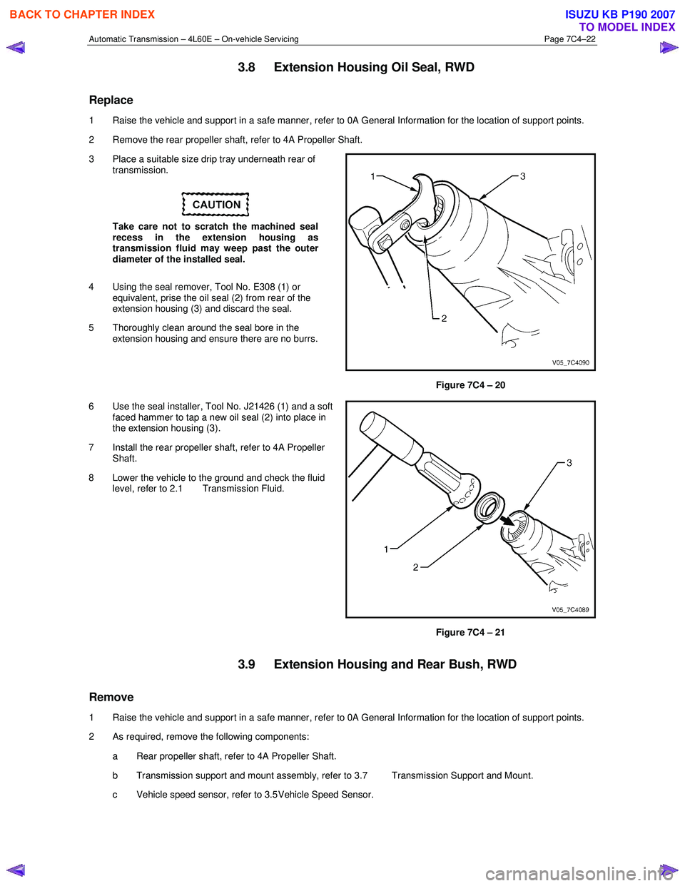
4 Using the seal remover, Tool No. E308 (1) or equivalent, prise the oil seal (2) from rear of the
extension housing (3) and discard the seal.
5 Thoroughly clean around the seal bore in the extension housing and ensure there are no burrs.
Figure 7C4 – 20
6 Use the seal installer, Tool No. J21426 (1) and a soft faced hammer to tap a new oil seal (2) into place in
the extension housing (3).
7 Install the rear propeller shaft, refer to 4A Propeller Shaft.
8 Lower the vehicle to the ground and check the fluid level, refer to 2.1 Transmission Fluid.
Figure 7C4 – 21
3.9 Extension Housing and Rear Bush, RWD
Remove
1 Raise the vehicle and support in a safe manner, refer to 0A General Information for the location of support points.
2 As required, remove the following components:
a Rear propeller shaft, refer to 4A Propeller Shaft.
b Transmission support and mount assembly, refer to 3.7 Transmission Support and Mount.
c Vehicle speed sensor, refer to 3.5 Vehicle Speed Sensor.
BACK TO CHAPTER INDEX
TO MODEL INDEX
ISUZU KB P190 2007
Page 3956 of 6020
Automatic Transmission – 4L60E – On-vehicle Servicing Page 7C4–43
If the verifier disc does not clip into place, the
quick-connect fitting is not engaged, rectify
as required.
10 As a security check, push and clip each verification disc into place over the quick-connect fittings. If difficulty is experienced, repeat the installation process until the verification disc can be clipped into place over the radiator
quick-connect fitting.
11 Snap the outlet cooler line (4) in the clip (5) of the radiator fan shroud.
12 Ensure the routeing of the cooler lines is correct and there is no fouling of the lines.
13 Tighten the screw attaching the cooler lines bracket to the correct torque specifications.
Transmission cooler lines bracket
attaching screw torque specification .................. 23.0 Nm
14 If required, top up the transmission fluid level (cold).
15 Start the engine and check for any fluid leak at the fittings. If a leak is found, stop the engine and rectify the leak.
16 Check and top up the transmission fluid to the correct level as required, refer to 2.1 Transmission Fluid.
3.18 Transmission Assembly
Remove
Disconnection of the battery affects certain
vehicle electronic systems. Refer to 6D1-3
Battery, before disconnecting the battery.
1 Disconnect the battery ground lead.
2 Raise the vehicle and support in a safe manner, refer to 0A General Information for the location of support points.
3 Remove the heat shield from the neutral start and back-up lamp switch, gently prise the selector cable from the transmission external manual shaft linkage and remove the selector cable from the bracket, refer to
3.3 Selector Cable Assembly.
4 Disconnect the harness connectors from the following:
a Vehicle speed sensor, refer to 3.5 Vehicle Speed Sensor.
b Neutral start and back-up switch, refer to 3.4 Neutral Start and Back-up Lamp Switch.
c For the following on four wheel drive vehicles (4W D), refer to 7D Transfer Case and Adaptor Housing:
• neutral switch,
• 2WD – 4WD shift actuator switch,
• speed sensor.
NOTE
If the battery is connected, avoid turning the
ignition switch to the ON position, as the transfer
case control module (TTCM) must first be
removed (memory to be cleared as Check 4W D
Indicator will light).
5 Remove the following components: a Front and centre exhaust assemblies, refer to 6F Exhaust System.
BACK TO CHAPTER INDEX
TO MODEL INDEX
ISUZU KB P190 2007