2007 ISUZU KB P190 Wiring harness
[x] Cancel search: Wiring harnessPage 3027 of 6020
Engine Mechanical – V6 Page 6A1–250
Page 6A1–250
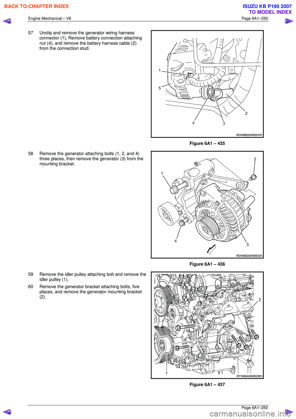
57 Unclip and remove the generator wiring harness
connector (1), Remove ba ttery connection attaching
nut (4), and remove the battery harness cable (2)
from the connection stud.
Figure 6A1 – 435
58 Remove the generator attaching bolts (1, 2, and 4) three places, then remove the generator (3) from the
mounting bracket.
Figure 6A1 – 436
59 Remove the idler pulley attaching bolt and remove the idler pulley (1).
60 Remove the generator bracket attaching bolts, five places, and remove the generator mounting bracket
(2).
Figure 6A1 – 437
BACK TO CHAPTER INDEX
TO MODEL INDEX
ISUZU KB P190 2007
Page 3029 of 6020
Engine Mechanical – V6 Page 6A1–252
Page 6A1–252
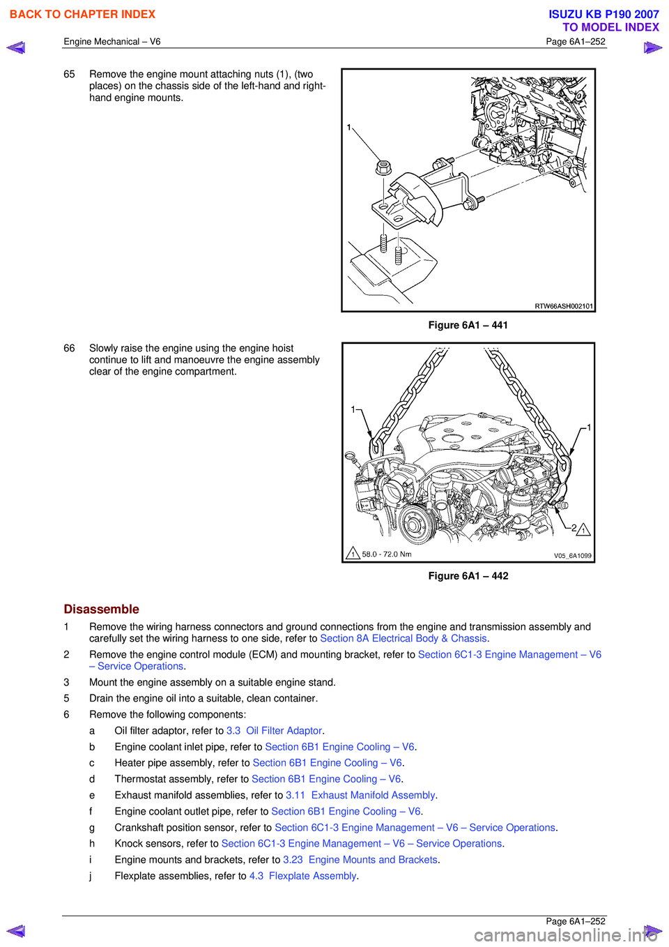
65 Remove the engine mount attaching nuts (1), (two
places) on the chassis si de of the left-hand and right-
hand engine mounts.
Figure 6A1 – 441
66 Slowly raise the engine using the engine hoist continue to lift and manoeuvre the engine assembly
clear of the engine compartment.
Figure 6A1 – 442
Disassemble
1 Remove the wiring harness connectors and ground connec tions from the engine and transmission assembly and
carefully set the wiring harness to one side, refer to Section 8A Electrical Body & Chassis.
2 Remove the engine control module (ECM) and mounting bracket, refer to Section 6C1-3 Engine Management – V6
– Service Operations .
3 Mount the engine assembly on a suitable engine stand.
5 Drain the engine oil into a suitable, clean container.
6 Remove the following components: a Oil filter adaptor, refer to 3.3 Oil Filter Adaptor.
b Engine coolant inlet pipe, refer to Section 6B1 Engine Cooling – V6.
c Heater pipe assembly, refer to Section 6B1 Engine Cooling – V6.
d Thermostat assembly, refer to Section 6B1 Engine Cooling – V6.
e Exhaust manifold a ssemblies, refer to 3.11 Exhaust Manifold Assembly .
f Engine coolant outlet pipe, refer to Section 6B1 Engine Cooling – V6.
g Crankshaft position sensor, refer to Section 6C1-3 Engine Management – V6 – Service Operations.
h Knock sensors, refer to Section 6C1-3 Engine Management – V6 – Service Operations.
i Engine mounts and brackets, refer to 3.23 Engine Mounts and Brackets.
j Flexplate assemblies, refer to 4.3 Flexplate Assembly.
BACK TO CHAPTER INDEX
TO MODEL INDEX
ISUZU KB P190 2007
Page 3128 of 6020
Engine Mechanical – V6 Page 6A1–351
Page 6A1–351
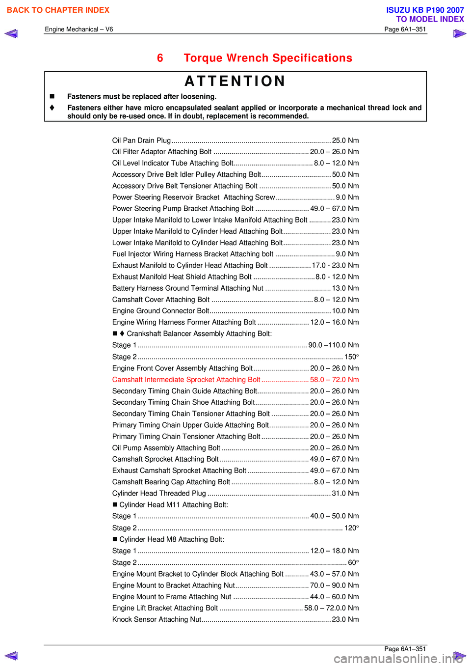
6 Torque Wrench Specifications
ATTENTION
�„ Fasteners must be replaced after loosening.
Fasteners either have micro encapsulated sealant a pplied or incorporate a mechanical thread lock and
should only be re-used once. If in doubt, replacement is recommended.
Oil Pan Drain Plug ................................................................................ 25.0 Nm
Oil Filter Adaptor Attach ing Bolt................................................ 20.0 – 26.0 Nm
Oil Level Indicator Tube Atta ching Bolt........................................ 8.0 – 12.0 Nm
Accessory Drive Belt Idler Pu lley Attaching Bolt................................... 50.0 Nm
Accessory Drive Belt Tensio ner Attaching Bolt .................................... 50.0 Nm
Power Steering Reserv oir Bracket Attaching Screw.............................. 9.0 Nm
Power Steering Pump Bracket A ttaching Bolt ........................... 49. 0 – 67.0 Nm
Upper Intake Manifold to Lower Intake Manifold Attaching Bolt ........... 23.0 Nm
Upper Intake Manifold to Cylinder Head Attaching Bolt........................ 23.0 Nm
Lower Intake Manifold to Cylind er Head Attaching Bolt........................ 23.0 Nm
Fuel Injector Wiring Harness Br acket Attaching bolt .............................. 9. 0 Nm
Exhaust Manifold to Cylinder He ad Attaching Bolt..................... 17.0 - 23.0 Nm
Exhaust Manifold Heat Shield Attaching Bolt ............................... 8.0 - 12.0 Nm
Battery Harness Ground Terminal Attaching Nut ................................. 13. 0 Nm
Camshaft Cover Attachi ng Bolt................................................... 8.0 – 12.0 Nm
Engine Ground Connec tor Bolt............................................................. 10.0 Nm
Engine Wiring Harness Former A ttaching Bolt .......................... 12.0 – 16.0 Nm
�„ Crankshaft Balancer A ssembly Attaching Bolt:
Stage 1 ..................................................................................... 90.0 –110.0 Nm
Stage 2 ....................................................................................................... 150 °
Engine Front Cover Assembly A ttaching Bolt ............................ 20. 0 – 26.0 Nm
Camshaft Intermediate Sprocket Attaching Bolt ........................ 58. 0 – 72.0 Nm
Secondary Timing Chai n Guide Attaching Bolt.......................... 20.0 – 26.0 Nm
Secondary Timing Chai n Shoe Attaching Bolt ........................... 20.0 – 26.0 Nm
Secondary Timing Chain Tensioner Attachi ng Bolt ................... 20.0 – 26.0 Nm
Primary Timing Chain Upper Gui de Attaching Bolt.................... 20.0 – 26.0 Nm
Primary Timing Chain Tensioner Attaching Bolt........................ 20. 0 – 26.0 Nm
Oil Pump Assembly Attach ing Bolt............................................ 20.0 – 26.0 Nm
Camshaft Sprocket Attachi ng Bolt............................................. 49.0 – 67.0 Nm
Exhaust Camshaft Sprocket Atta ching Bolt............................... 49.0 – 67.0 Nm
Camshaft Bearing Cap Attach ing Bolt......................................... 8.0 – 12.0 Nm
Cylinder Head Thr eaded Plug.............................................................. 31.0 Nm
�„ Cylinder Head M11 Attaching Bolt:
Stage 1 ...................................................................................... 40.0 – 50.0 Nm
Stage 2 ....................................................................................................... 120 °
�„ Cylinder Head M8 Attaching Bolt:
Stage 1 ...................................................................................... 12.0 – 18.0 Nm
Stage 2 ......................................................................................................... 60 °
Engine Mount Bracket to Cylinder Bl ock Attaching Bolt............ 43.0 – 57.0 Nm
Engine Mount to Bracket Atta ching Nut..................................... 70.0 – 90.0 Nm
Engine Mount to Frame Atta ching Nut...................................... 44.0 – 60.0 Nm
Engine Lift Bracket Attachi ng Bolt.......................................... 58.0 – 72.0.0 Nm
Knock Sensor Attach ing Nut................................................................. 23.0 Nm
BACK TO CHAPTER INDEX
TO MODEL INDEX
ISUZU KB P190 2007
Page 3150 of 6020
Engine Cooling – V6 Engine Page 6B1–15
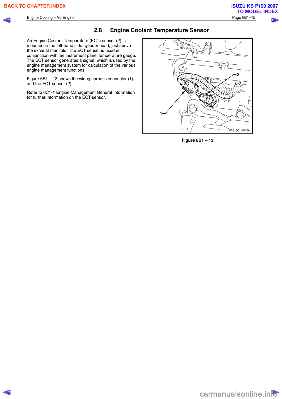
2.8 Engine Coolant Temperature Sensor
An Engine Coolant Temperature (ECT) sensor (2) is
mounted in the left-hand side cylinder head, just above
the exhaust manifold. The ECT sensor is used in
conjunction with the instrument panel temperature gauge.
The ECT sensor generates a signal, which is used by the
engine management system for calculation of the various
engine management functions.
Figure 6B1 – 13 shows the wiring harness connector (1)
and the ECT sensor (2).
Refer to 6C1-1 Engine Management General Information
for further information on the ECT sensor.
Figure 6B1 – 13
BACK TO CHAPTER INDEX
TO MODEL INDEX
ISUZU KB P190 2007
Page 3170 of 6020
Engine Cooling – V6 Engine Page 6B1–35
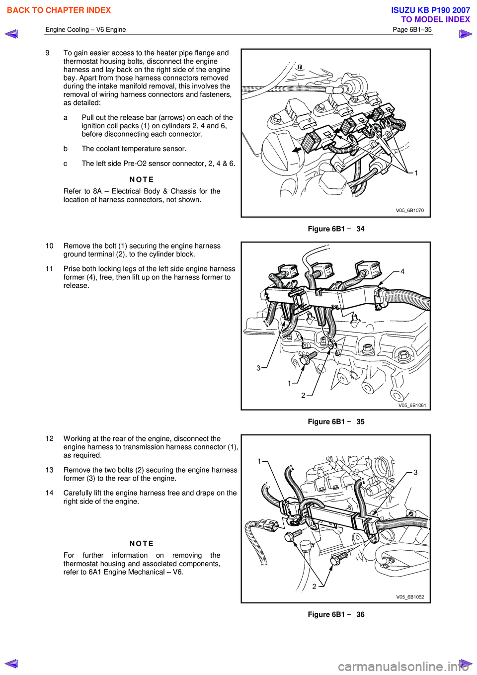
9 To gain easier access to the heater pipe flange and
thermostat housing bolts, disconnect the engine
harness and lay back on the right side of the engine
bay. Apart from those harness connectors removed
during the intake manifold removal, this involves the
removal of wiring harness connectors and fasteners,
as detailed:
a Pull out the release bar (arrows) on each of the ignition coil packs (1) on cylinders 2, 4 and 6,
before disconnecting each connector.
b The coolant temperature sensor.
c The left side Pre-O2 sensor connector, 2, 4 & 6.
NOTE
Refer to 8A – Electrical Body & Chassis for the
location of harness connectors, not shown.
Figure 6B1 –
––
–
34
10 Remove the bolt (1) securing the engine harness ground terminal (2), to the cylinder block.
11 Prise both locking legs of the left side engine harness former (4), free, then lift up on the harness former to
release.
Figure 6B1 –
––
–
35
12 W orking at the rear of the engine, disconnect the engine harness to transmission harness connector (1),
as required.
13 Remove the two bolts (2) securing the engine harness former (3) to the rear of the engine.
14 Carefully lift the engine harness free and drape on the right side of the engine.
NOTE
For further information on removing the
thermostat housing and associated components,
refer to 6A1 Engine Mechanical – V6.
Figure 6B1 –
––
–
36
BACK TO CHAPTER INDEX
TO MODEL INDEX
ISUZU KB P190 2007
Page 3173 of 6020
Engine Cooling – V6 Engine Page 6B1–38
Install
Always wear protective safety glasses when
working with spring-loaded devices. Failure to
do so could result in eye injury.
1 Install the thermostat into the housing (reverse to removal procedure).
2 Ensure that the engine block and thermostat housing mating surfaces are clean and dry.
3 Install a new gasket to the thermostat housing.
4 Install the thermostat housing to the engine block and secure with the attaching bolts (with rubber grommets installed). Tighten all bolts to the correct torque specification.
Thermostat housing to engine
block bolt torque specification ..............................10 N.m
5 Ensure that the heater pipe assembly and thermostat housing mating surfaces are clean and dry.
6 Install new O-rings to the heater pipe assembly.
7 Install heater pipe assembly to thermostat housing and secure with the attaching bolts. Tighten all bolts to the correct torque specification.
Heater pipe assembly to thermostat
housing bolt torque specification ..........................10 N.m
8 Install heater pipe assembly to right-hand cylinder head bolt. Tighten bolt to the correct torque specification. Heater pipe assembly to cylinder
head bolt torque specification ..............................35 N.m
Always wear protective safety glasses when
working with spring type hose clamps. Failure
to do so could result in eye injury.
9 Reinstall the engine wiring harness, securing the rear harness former to the rear of the engine with the two retaining bolts, tightened to the correct torque specification.
Rear engine harness former
retaining bolts torque specification .......................15 N.m
10 Reinstall the left side engine harness former to the two locating pegs, then push inward to secure.
11 Reinstall the bolt securing the engine harness ground terminal, to the left side of the cylinder block and tighten to the correct torque specification.
Engine harness ground terminal
attaching bolt torque specification ........................12 N.m
12 Reinstall each wiring harness connector to its correct location, ensuring that all security clips are installed correctly.
13 Connect the heater hoses to the heater pipe assembly.
14 Install the coolant inlet pipe. Refer to 3.12 Coolant Inlet Pipe in this Section.
15 Close the radiator drain tap on the lower LHS of the radiator and remove the piece of rubber tubing to the tap outlet.
16 Reinstall the complete intake manifold assembly. Refer to 6A1 Engine Mechanical.
17 Refill cooling system. Refer to 3.3 Draining and Filling Cooling System in this Section.
BACK TO CHAPTER INDEX
TO MODEL INDEX
ISUZU KB P190 2007
Page 3184 of 6020
Engine Cooling – V6 Engine Page 6B1–49
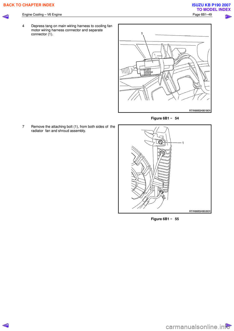
4 Depress tang on main wiring harness to cooling fan
motor wiring harness connector and separate
connector (1).
Figure 6B1 –
––
–
54
7 Remove the attaching bolt (1), from both sides of the radiator fan and shroud assembly.
Figure 6B1 –
––
–
55
BACK TO CHAPTER INDEX
TO MODEL INDEX
ISUZU KB P190 2007
Page 3186 of 6020
Engine Cooling – V6 Engine Page 6B1–51
Disassemble
1 Remove cooling fan and shroud assembly as previously described.
NOTE
Neither fan is to be separated from its fan motor.
The assembly is carefully balanced during
manufacture and duplicating this balance on
reassembly, is not possible.
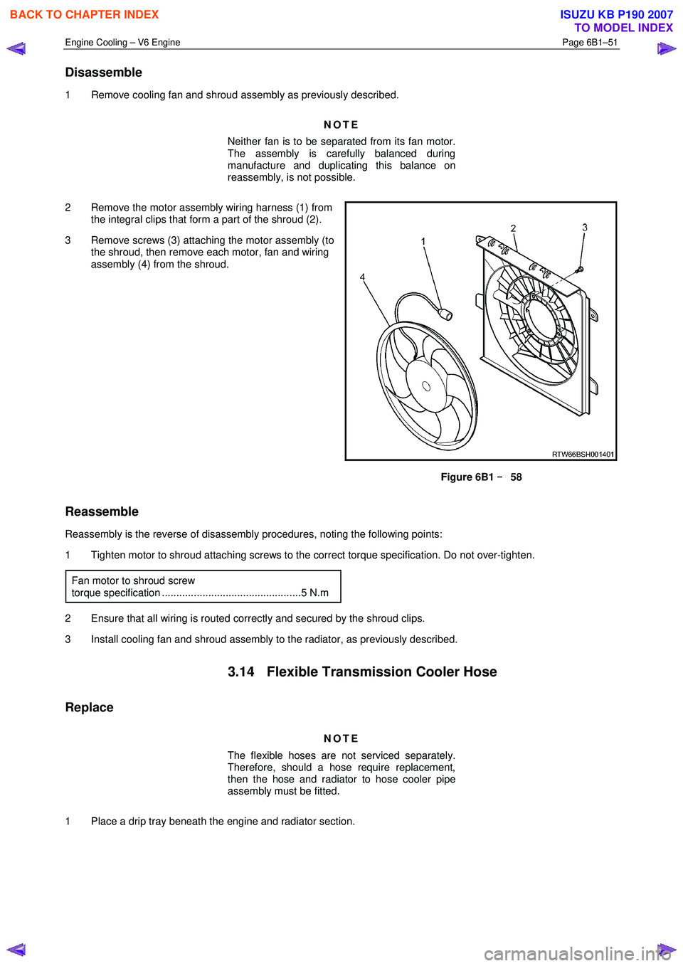
2 Remove the motor assembly wiring harness (1) from the integral clips that form a part of the shroud (2).
3 Remove screws (3) attaching the motor assembly (to the shroud, then remove each motor, fan and wiring
assembly (4) from the shroud.
Figure 6B1 –
––
–
58
Reassemble
Reassembly is the reverse of disassembly procedures, noting the following points:
1 Tighten motor to shroud attaching screws to the correct torque specification. Do not over-tighten.
Fan motor to shroud screw
torque specification ................................................5 N.m
2 Ensure that all wiring is routed correctly and secured by the shroud clips.
3 Install cooling fan and shroud assembly to the radiator, as previously described.
3.14 Flexible Transmission Cooler Hose
Replace
NOTE
The flexible hoses are not serviced separately.
Therefore, should a hose require replacement,
then the hose and radiator to hose cooler pipe
assembly must be fitted.
1 Place a drip tray beneath the engine and radiator section.
BACK TO CHAPTER INDEX
TO MODEL INDEX
ISUZU KB P190 2007