2007 ISUZU KB P190 Wiring harness
[x] Cancel search: Wiring harnessPage 3189 of 6020
Engine Cooling – V6 Engine Page 6B1–54
3.15 Radiator
Remove
Refer to 3.1 Service Notes in this Section, for
important safety items.
1 Allow engine to cool to ambient temperature (less than 50 ° C), then remove coolant filler cap.
Disconnection of the battery affects certain
vehicle electronic systems. Refer to 00
Warnings, Cautions and Notes, before
removing the ground lead.
2 Disconnect the battery ground lead. Refer to 8A – Electrical Body & Chassis.
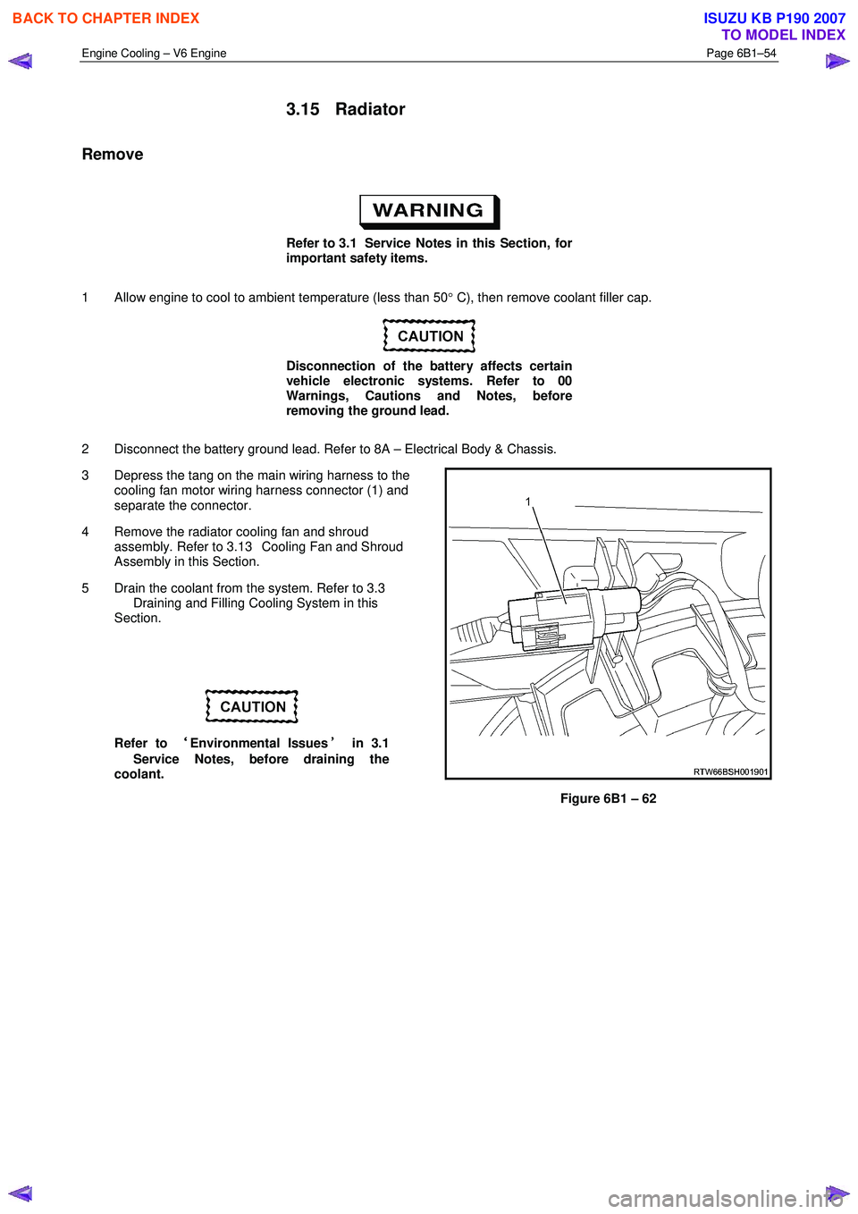
3 Depress the tang on the main wiring harness to the cooling fan motor wiring harness connector (1) and
separate the connector.
4 Remove the radiator cooling fan and shroud assembly. Refer to 3.13 Cooling Fan and Shroud
Assembly in this Section.
5 Drain the coolant from the system. Refer to 3.3 Draining and Filling Cooling System in this
Section.
Refer to ‘
‘‘
‘
Environmental Issues ’
’’
’
in 3.1
Service Notes, before draining the
coolant.
Figure 6B1 – 62
BACK TO CHAPTER INDEX
TO MODEL INDEX
ISUZU KB P190 2007
Page 3269 of 6020
Engine Management – V6 – General Information Page 6C1-1–27
4.13 Fuel Rail Assembly
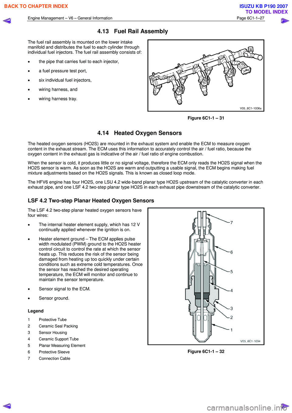
The fuel rail assembly is mounted on the lower intake
manifold and distributes the fuel to each cylinder through
individual fuel injectors. The fuel rail assembly consists of:
• the pipe that carries fuel to each injector,
• a fuel pressure test port,
• six individual fuel injectors,
• wiring harness, and
• wiring harness tray.
Figure 6C1-1 – 31
4.14 Heated Oxygen Sensors
The heated oxygen sensors (HO2S) are mounted in the exhaust system and enable the ECM to measure oxygen
content in the exhaust stream. The ECM uses this information to accurately control the air / fuel ratio, because the
oxygen content in the exhaust gas is indicative of the air / fuel ratio of engine combustion.
W hen the sensor is cold, it produces little or no signal voltage, therefore the ECM only reads the HO2S signal when the
HO2S sensor is warm. As soon as the HO2S are warm and outputting a usable signal, the ECM begins making fuel
mixture adjustments based on the HO2S signals. This is known as closed loop mode.
The HFV6 engine has four HO2S, one LSU 4.2 wide-band planar type HO2S upstream of the catalytic converter in each
exhaust pipe, and one LSF 4.2 two-step planar type HO2S in each exhaust pipe downstream of the catalytic converter.
LSF 4.2 Two-step Planar Heated Oxygen Sensors
The LSF 4.2 two-step planar heated oxygen sensors have
four wires:
• The internal heater element supply, which has 12 V
continually applied whenever the ignition is on.
• Heater element ground – The ECM applies pulse
width modulated (PW M) ground to the HO2S heater
control circuit to control the rate at which the sensor
heats up. This reduces the risk of the sensor being
damaged from heating up too quickly under certain
conditions such as extreme cold temperatures. Once
the sensor has reached the desired operating
temperature, the ECM will monitor and continue to
maintain the sensor temperature.
• Sensor signal to the ECM.
• Sensor ground.
Legend
1 Protective Tube
2 Ceramic Seal Packing
3 Sensor Housing
4 Ceramic Support Tube
5 Planar Measuring Element
6 Protective Sleeve
7 Connection Cable
Figure 6C1-1 – 32
BACK TO CHAPTER INDEX
TO MODEL INDEX
ISUZU KB P190 2007
Page 3297 of 6020
Engine Management – V6 – Diagnostics Page 6C1-2–19
• Do not start the engine if the battery terminal is not properly secured to the battery.
• Do not disconnect or reconnect the following while the ignition is switched on or when the engine is running:
− Any engine management system component electrical wiring connector, or
− Battery terminal leads.
• Ensure the correct procedure for disconnecting and connecting engine management system electrical wiring
connectors is always followed. For information on the correct procedure for disconnecting and connecting specific
wiring connectors, refer to 6C1-3 Engine Management – V6 – Service Operations.
• Ensure that all wiring harness connectors are fitted correctly.
• W hen steam or pressure cleaning engines, do not direct the cleaning nozzle at engine management system
components.
• Do not clear any DTCs unless instructed.
• The fault must be present when using the diagnostic trouble code (DTC) diagnostic tables. Otherwise,
misdiagnosis or replacement of good parts may occur.
• Do not touch the ECM connector pins or soldered components on the ECM circuit board to prevent ECM
Electrostatic Discharge damage. Refer to 8A Electrical - Body and Chassis for information on Electrostatic
Discharge.
• Use only the test equipment specified in the diagnostic tables as other test equipment may give incorrect results or
damage good components.
• The ECM is designed to withstand normal current draw associated with vehicle operations. However, the following
fault conditions or incorrect test procedure may overload the ECM internal circuit and damage the ECM:
− A short to voltage fault condition in any of the ECM low reference circuits may cause internal ECM and / or
sensor damage. Therefore, any short to voltage fault condition in the ECM low reference circuits must be
rectified before replacing a faulty component.
− A short to ground fault condition in any of the ECM 5 V reference circuits may cause internal ECM and / or
sensor damage. Therefore, any short to ground fault condition in the ECM 5 V reference circuits must be
rectified before replacing a faulty component.
− W hen using a test lamp to test an electrical circuit, do not use any of the ECM low reference circuits or 5 V
reference circuits as a reference point. Otherwise, excessive current draw from the test lamp may damage
the ECM.
• Disregard DTCs that set while performing the following diagnostic Steps:
− Using Tech 2 actuator tests, or
− Disconnecting an engine management system sensor connector then switching on the ignition.
• After completing the required diagnostics and service operations, road test the vehicle to ensure correct engine
management system operation.
4.3 Preliminary Checks
The preliminary checks are a set of visual and physical checks or inspections that may quickly identify engine
management system fault condition.
• Refer to the appropriate Service Techlines for relevant information regarding the fault condition.
• Ensure the battery is fully charged.
• Inspect the battery connections for corrosion or a loose terminal.
• Ensure that all engine management system related fuses are serviceable.
• Inspect for incorrect aftermarket theft deterrent devices, lights or mobile phone installation.
• Ensure there is no speaker magnet positioned too close to any electronic module that contains relays.
• Inspect the engine wiring harness for proper connections, pinches or cuts.
• Ensure that all engine management related electrical wiring connectors are fitted correctly.
• Inspect the ECM ground connections for corrosion, loose terminal or incorrect position.
BACK TO CHAPTER INDEX
TO MODEL INDEX
ISUZU KB P190 2007
Page 3298 of 6020
Engine Management – V6 – Diagnostics Page 6C1-2–20
• Ensure the resistance between the ECM housing and the battery negative cable is less than 0.5 Ω.
• Check the ECM bracket fasteners for correct torque value.
• Check all engine management related components for correct installation.
• Inspect the vacuum hoses for splits, kinks, oil contamination and proper connections, refer to the vehicle emission
control information label. Check the hoses thoroughly for any type of leak or restriction.
• Inspect the air intake ducts for being collapsed, split or for having damaged areas.
• Inspect for air leaks at the throttle body mounting area, mass air flow (MAF) sensor, intake manifold and intake
manifold sealing surfaces.
• Check for wiring harness routing that may be positioned too close to a high voltage or high current device such as
the following:
− Secondary ignition components, and
− Motors and generators.
NOTE
High voltage or high current devices may induce
electrical noise on a circuit, which can interfere
with normal circuit operation.
4.4 Diagnostic System Check
Description
The engine management diagnostic procedure is organised in a logical structure that begins with the Diagnostic System
Check. The Diagnostic System Check directs the diagnostic procedure to the logical steps necessary to diagnose an
engine driveability fault condition.
Test Description
The following numbers refer to the step numbers in the diagnostic table:
6 Tests the integrity of the GM LAN serial data communication circuit. A PIM DTC sets if the PIM detects a fault condition in the communication circuit. A fault condition on the serial data communication circuit may trigger
multiple DTCs on other sensors and components.
Step Action Yes No
1 Have you read the basic requirements?
Go to Step 2 Refer to
4.1 Basic
Requirements
2 Have you read the diagnostic precautions?
Go to Step 3 Refer to
4.2 Diagnostic Precautions
3 Have you performed the preliminary checks?
Go to Step 4 Refer to
4.3 Preliminary Checks
4 Using Tech 2, attempt to communicate with the PIM.
Does the PIM fail to communicate? Refer to 6E1
Powertrain Interface Module – V6 Go to Step 5
5 Does DTC B3902, C0550, U2100, U2105, U2106, P0633, or P1611
also set in the PIM? Refer to 6E1
Powertrain Interface Module – V6 Go to Step 6
6 Using Tech 2, view and record DTCs set at the ECM and TCM.
Does Tech 2 display any DTC? Go to Step 7 Refer to
5.1 Symptoms
Diagnosis Table
BACK TO CHAPTER INDEX
TO MODEL INDEX
ISUZU KB P190 2007
Page 3301 of 6020

Engine Management – V6 – Diagnostics Page 6C1-2–23
• there is no Current DTC but a History DTC is stored.
Diagnostic Table
Checks Actions
Preliminary
• Perform the preliminary checks. Refer to 4.3 Preliminary Checks in this
Section.
• Gather information from the customer regarding the conditions that trigger the
intermittent fault such as:
• At what engine or ambient temperature range does the fault occur?
• Does the fault occur when operating aftermarket electrical equipment inside
the vehicle?
• Does the fault occur on rough roads or in wet road conditions?
• If the intermittent fault is a start and then stall condition, check the immobiliser
system. Refer to 11A Immobiliser.
Tech 2 Tests The following are lists of Tech 2 diagnostic tests that may be used to diagnose
intermittent faults:
• W riggle test the suspected wiring harness and connectors while observing Tech 2
operating parameters. If Tech 2 read-out fluctuates during this procedure, check
the tested wiring harness circuit for a loose connection.
• Observe the freeze frame / failure records for the suspected history DTC and then
operate the vehicle in the conditions that triggers the intermittent fault while an
assistant observes the suspected Tech 2 operating parameter data.
• Capture and store data in the snapshot mode when the fault occurs. The stored
data may be played back at a slower rate to aid diagnostics. Refer to Tech 2 User
Instructions for further information on the Snapshot function.
• Compare the engine operating parameters of the engine being diagnosed to the
engine operating parameters of a known good engine.
Malfunction Indicator Lamp The following conditions may cause an intermittent Malfunction Indicator Lamp fault with no DTC listed:
• Electromagnetic interference (EMI) caused by a faulty relay, ECM controlled
solenoid, switch or other external source.
• Incorrect installation of aftermarket electrical equipment such as the following:
• mobile phones,
• lights, or
• radio equipment.
• ECM grounds are loose.
BACK TO CHAPTER INDEX
TO MODEL INDEX
ISUZU KB P190 2007
Page 3326 of 6020
Engine Management – V6 – Diagnostics Page 6C1-2–48
Additional Information
• Use the J 35616-B Connector Test Adapter Kit for any test that requires probing the ECM harness connector or a
component harness connector.
• Inspect the ignition coils for aftermarket devices. An aftermarket device connected to the ignition coil circuits, may
cause a condition with the ignition coils.
• For an intermittent fault condition, refer to 5.2 Intermittent Fault Conditions in this Section.
• To assist diagnosis, refer to 3 W iring Diagrams and Connector Charts in this Section, for the system wiring
diagram and connector charts.
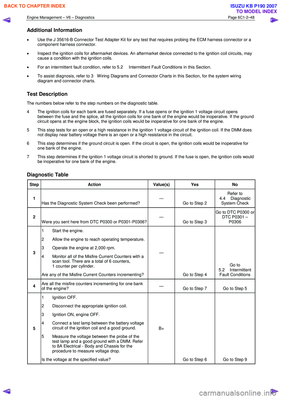
Test Description
The numbers below refer to the step numbers on the diagnostic table.
4 The ignition coils for each bank are fused separately. If a fuse opens or the ignition 1 voltage circuit opens between the fuse and the splice, all the ignition coils for one bank of the engine would be inoperative. If the ground
circuit opens at the engine block, the ignition coils would be inoperative for one bank of the engine.
5 This step tests for an open or a high resistance in the ignition 1 voltage circuit of the ignition coil. If the DMM does not display near battery voltage there is an open or a high resistance in the circuit.
6 This step determines if the ground circuit is open. If the circuit is open, the ignition coils would be inoperative for one bank of the engine.
7 This step determines if the ignition 1 voltage circuit is shorted to ground. If the fuse is open, the ignition coils would be inoperative for one bank of the engine.
Diagnostic Table
Step Action Value(s) Yes No
1
Has the Diagnostic System Check been performed? —
Go to Step 2 Refer to
4.4 Diagnostic System Check
2 W ere you sent here from DTC P0300 or P0301-P0306? —
Go to Step 3 Go to DTC P0300 or
DTC P0301 – P0306
3 1 Start the engine.
2 Allow the engine to reach operating temperature.
3 Operate the engine at 2,000 rpm.
4 Monitor all of the Misfire Current Counters with a scan tool. There are a total of 6 counters,
1 counter per cylinder.
Are any of the Misfire Current Counters incrementing? —
Go to Step 4 Go to
5.2 Intermittent Fault Conditions
4 Are all the misfire counters incrementing for one bank
of the engine? —
Go to Step 7 Go to Step 5
5 1 Ignition OFF.
2 Disconnect the appropriate ignition coil.
3 Ignition ON, engine OFF.
4 Connect a test lamp between the battery voltage circuit of the ignition coil and a good ground.
5 Measure the voltage between the probe of the test lamp and a good ground with a DMM. Refer
to 8A Electrical - Body and Chassis for the
procedure to measure voltage drop.
Is the voltage at the specified value? B+
Go to Step 6 Go to Step 9
BACK TO CHAPTER INDEX
TO MODEL INDEX
ISUZU KB P190 2007
Page 3342 of 6020
Engine Management – V6 – Diagnostics Page 6C1-2–64
• Inspect the HO2S wiring harness for contact with the exhaust system.
• The front and the rear HO2Ss have a separate fuse connection. If both front or both the rear DTCs are set, the
appropriate HO2S ignition voltage circuit may be open.
• Since fault condition in a wiring connector may trigger DTCs, always test the connectors related to this diagnostic
procedure for shorted terminals or poor wiring connection before replacing any component. Refer to 8A Electrical -
Body and Chassis for information on electrical fault diagnosis.
• To assist diagnosis, refer to 3 W iring Diagrams and Connector Charts in this Section, for the system wiring
diagram and connector charts.
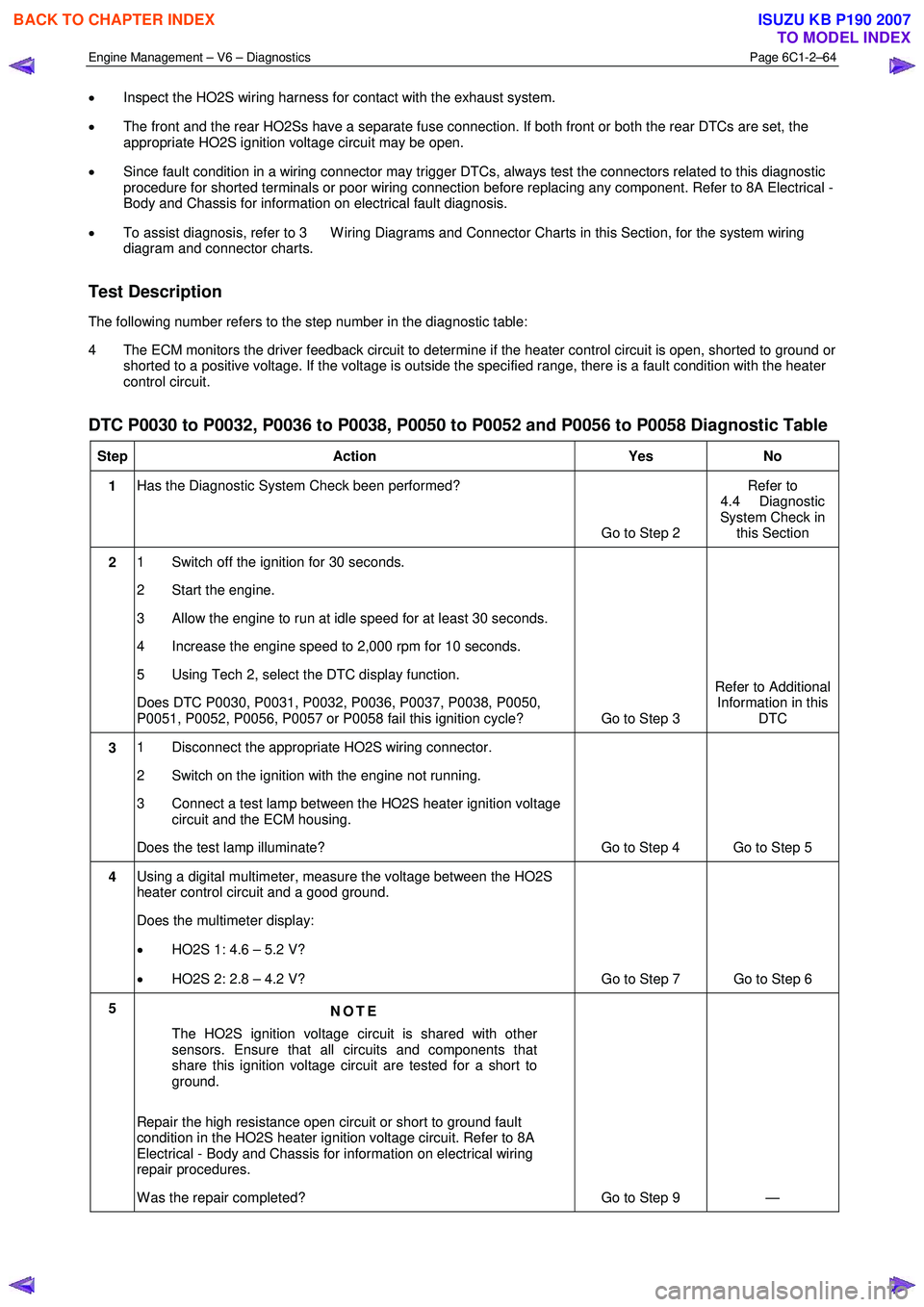
Test Description
The following number refers to the step number in the diagnostic table:
4 The ECM monitors the driver feedback circuit to determine if the heater control circuit is open, shorted to ground or shorted to a positive voltage. If the voltage is outside the specified range, there is a fault condition with the heater
control circuit.
DTC P0030 to P0032, P0036 to P0038, P0050 to P0052 and P0056 to P0058 Diagnostic Table
Step Action Yes No
1 Has the Diagnostic System Check been performed?
Go to Step 2 Refer to
4.4 Diagnostic
System Check in this Section
2 1 Switch off the ignition for 30 seconds.
2 Start the engine.
3 Allow the engine to run at idle speed for at least 30 seconds.
4 Increase the engine speed to 2,000 rpm for 10 seconds.
5 Using Tech 2, select the DTC display function.
Does DTC P0030, P0031, P0032, P0036, P0037, P0038, P0050,
P0051, P0052, P0056, P0057 or P0058 fail this ignition cycle? Go to Step 3 Refer to Additional
Information in this DTC
3 1 Disconnect the appropriate HO2S wiring connector.
2 Switch on the ignition with the engine not running.
3 Connect a test lamp between the HO2S heater ignition voltage circuit and the ECM housing.
Does the test lamp illuminate? Go to Step 4 Go to Step 5
4 Using a digital multimeter, measure the voltage between the HO2S
heater control circuit and a good ground.
Does the multimeter display:
• HO2S 1: 4.6 – 5.2 V?
• HO2S 2: 2.8 – 4.2 V? Go to Step 7 Go to Step 6
5
NOTE
The HO2S ignition voltage circuit is shared with other
sensors. Ensure that all circuits and components that
share this ignition voltage circuit are tested for a short to
ground.
Repair the high resistance open circuit or short to ground fault
condition in the HO2S heater ignition voltage circuit. Refer to 8A
Electrical - Body and Chassis for information on electrical wiring
repair procedures.
W as the repair completed? Go to Step 9 —
BACK TO CHAPTER INDEX
TO MODEL INDEX
ISUZU KB P190 2007
Page 3348 of 6020
Engine Management – V6 – Diagnostics Page 6C1-2–70
Additional Information
• The MAF sensor circuit DTCs is a Type B DTC. Refer to 1.4 Diagnostic Trouble Codes in this Section, for action
taken when a Type B DTC sets and conditions for clearing Type B DTC.
• Refer to 6C1-1 Engine Management – V6 – General Information for details of the MAF sensor operation.
• For an intermittent fault condition, refer to 5.2 Intermittent Fault Conditions in this Section.
• Inspect the MAF sensor for an incorrectly routed harness or if the harness is too close to the following:
− ignition coil,
− solenoids,
− relays, and
− motors.
• A low minimum air rate may cause this DTC to set during deceleration. Inspect for the following conditions:
− a plugged or a collapsed intake air duct, or a dirty air filter element,
− objects that block the MAF sensor air inlet screen, and
− sticking or dirty throttle plate or throttle bore.
• Any un-metered air that enters the engine may cause this DTC to set. Inspect for vacuum leaks in the following:
− intake manifold,
− throttle body,
− barometric pressure (BARO) sensor seal,
− EVAP canister purge valve seal,
− brake booster system,
− air induction system, and
− crankcase ventilation system.
• Since fault condition in a wiring connector may trigger DTCs, always test the connectors related to this diagnostic
procedure for shorted terminals or poor wiring connection before replacing any component. Refer to 8A Electrical -
Body and Chassis for information on electrical fault diagnosis.
• To assist diagnosis, refer to 3 W iring Diagrams and Connector Charts in this Section, for the system wiring
diagram and connector charts.
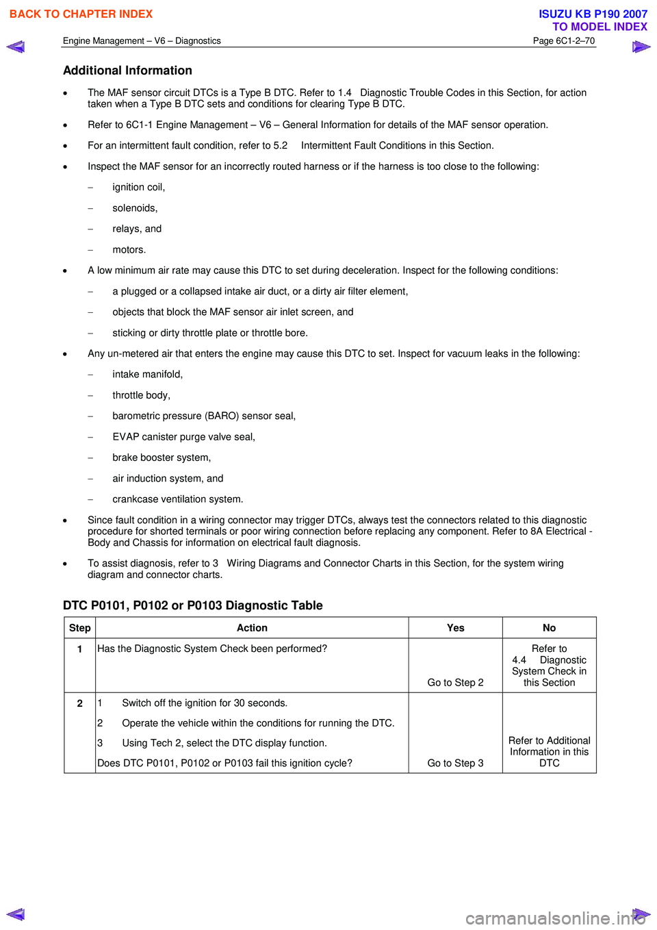
DTC P0101, P0102 or P0103 Diagnostic Table
Step Action Yes No
1 Has the Diagnostic System Check been performed?
Go to Step 2 Refer to
4.4 Diagnostic
System Check in this Section
2 1 Switch off the ignition for 30 seconds.
2 Operate the vehicle within the conditions for running the DTC.
3 Using Tech 2, select the DTC display function.
Does DTC P0101, P0102 or P0103 fail this ignition cycle? Go to Step 3 Refer to Additional
Information in this DTC
BACK TO CHAPTER INDEX
TO MODEL INDEX
ISUZU KB P190 2007