2007 ISUZU KB P190 ECO mode
[x] Cancel search: ECO modePage 1033 of 6020
6D – 32 ENGINE ELECTRICAL
MAGNETIC SWITCH
The following tests must be performed with the starter
motor fully assembled.
The yoke lead wire must be disconnected from the “M ”
terminal.
To prevent coil burning, complete each test as quickly as
possible (within three to five seconds).
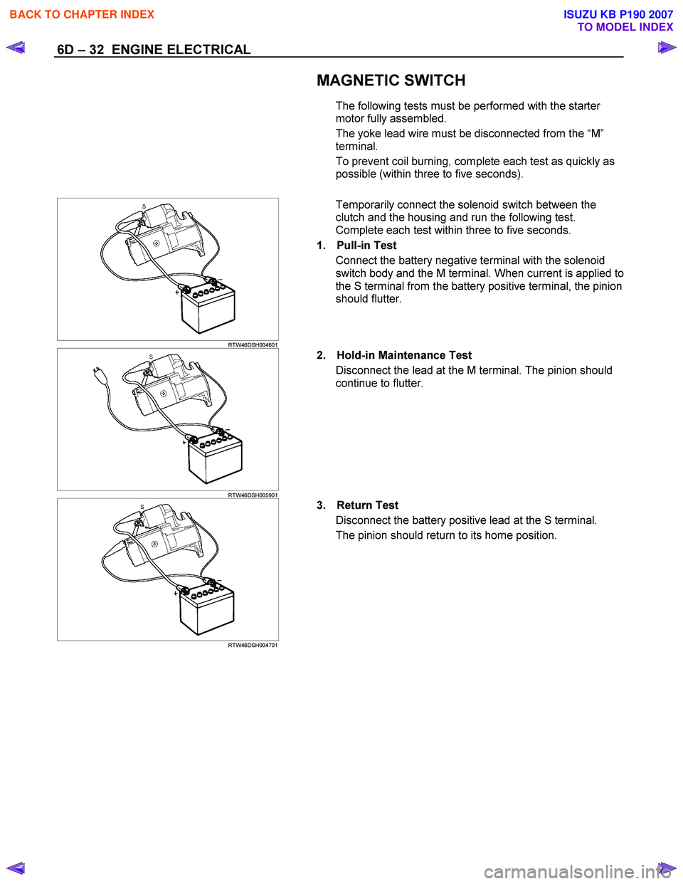
RTW46DSH004601
Temporarily connect the solenoid switch between the
clutch and the housing and run the following test.
Complete each test within three to five seconds.
1. Pull-in Test Connect the battery negative terminal with the solenoid
switch body and the M terminal. When current is applied to
the S terminal from the battery positive terminal, the pinion
should flutter.
RTW46DSH005901
2. Hold-in Maintenance Test
Disconnect the lead at the M terminal. The pinion should
continue to flutter.
RTW46DSH004701
3. Return Test
Disconnect the battery positive lead at the S terminal.
The pinion should return to its home position.
BACK TO CHAPTER INDEX
TO MODEL INDEX
ISUZU KB P190 2007
Page 1064 of 6020
6E-30 Engine Control System (4JH1)
Diagnostic Information And Prosedures
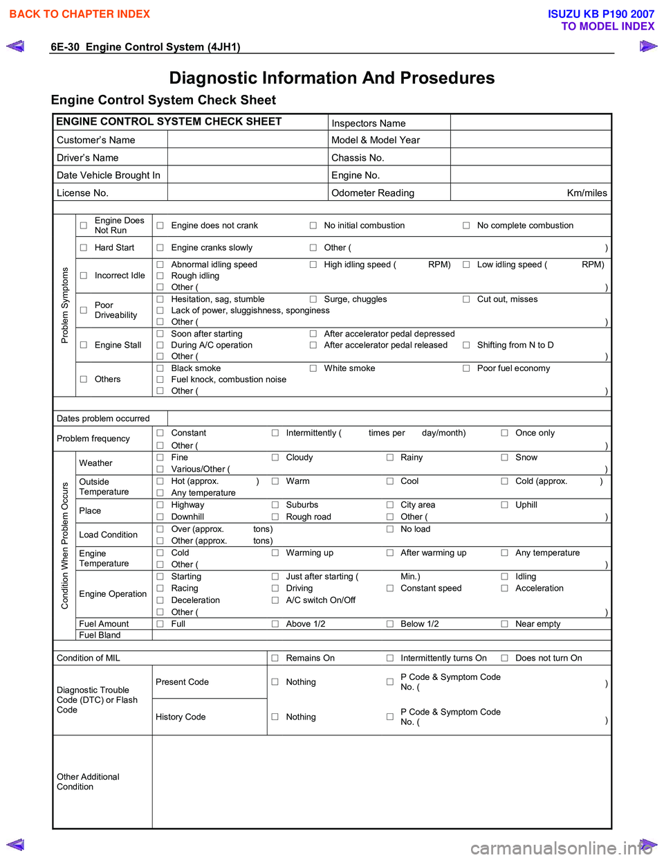
Engine Control System Check Sheet
ENGINE CONTROL SYSTEM CHECK SHEET Inspectors Name
Customer’s Name Model & Model Year
Driver’s Name Chassis No.
Date Vehicle Brought In Engine No.
License No. Odometer Reading Km/miles
□ Engine Does
Not Run □
Engine does not crank
□No initial combustion
□ No complete combustion
□
Hard Start
□ Engine cranks slowly
□Other ( )
□
Abnormal idling speed
□High idling speed ( RPM)
□ Low idling speed ( RPM)
□
Rough idling □
Incorrect Idle
□ Other ( )
□
Hesitation, sag, stumble
□Surge, chuggles
□ Cut out, misses
□
Lack of power, sluggishness, sponginess □
Poor
Driveability □ Other ( )
□ Soon after starting
□After accelerator pedal depressed
Engine Stall
□ During A/C operation
□After accelerator pedal released
□ Shifting from N to D □
□ Other ( )
□
Black smoke
□White smoke
□ Poor fuel economy
□
Fuel knock, combustion noise
Problem Symptoms
□
Others
□ Other ( )
Dates problem occurred
□
Constant
□Intermittently ( times per day/month)
□ Once only Problem frequency
□ Other (
)
□ Fine
□Cloudy
□Rainy
□ Snow Weather
□ Various/Other (
)
□ Hot (approx. )
□Warm
□Cool
□ Cold (approx. )Outside
Temperature □ Any temperature
□
Highway
□Suburbs
□City area
□ Uphill Place
□ Downhill
□Rough road
□Other (
)
□ Over (approx. tons)
□No load
Load Condition
□ Other (approx. tons)
□ Cold
□Warming up
□After warming up
□ Any temperature Engine
Temperature □ Other ( )
□
Starting
□Just after starting ( Min.)
□ Idling
□
Racing
□Driving
□Constant speed
□ Acceleration
□
Deceleration
□A/C switch On/Off Engine Operation
□ Other ( )
Fuel Amount
□ Full
□Above 1/2
□Below 1/2
□ Near empty
Condition When Problem Occurs
Fuel
Bland
Condition of MIL
□Remains On
□Intermittently turns On
□ Does not turn On
Present Code
□Nothing
□P Code & Symptom Code
No. ( )Diagnostic Trouble
Code (DTC) or Flash
Code History Code □Nothing
□P Code & Symptom Code
No. ( )
Other Additional
Condition
BACK TO CHAPTER INDEX
TO MODEL INDEX
ISUZU KB P190 2007
Page 1065 of 6020
Engine Control System (4JH1) 6E-31
Diagnostic Starting Point - Engine Controls
Begin the system diagnosis with Diagnostic System
Check - Engine Controls. The Diagnostic System Check
- Engine Controls will provide the following information:
• The identification of the control modules which
command the system.
• The ability of the control modules to communicate
through the serial data circuit.
• The identification of any stored diagnostic trouble
codes (DTCs) and the their statuses.
The use of the Diagnostic System Check - Engine
Controls will identify the correct procedure fo
r
diagnosing the system and where the procedure is
located.
Important:
Engine Control System Check Sheet must be used to
verify the complaint vehicle, you need to know the
correct (normal) operating behavior of the system and
verify that the customer complaint is a valid failure o
f
the system.
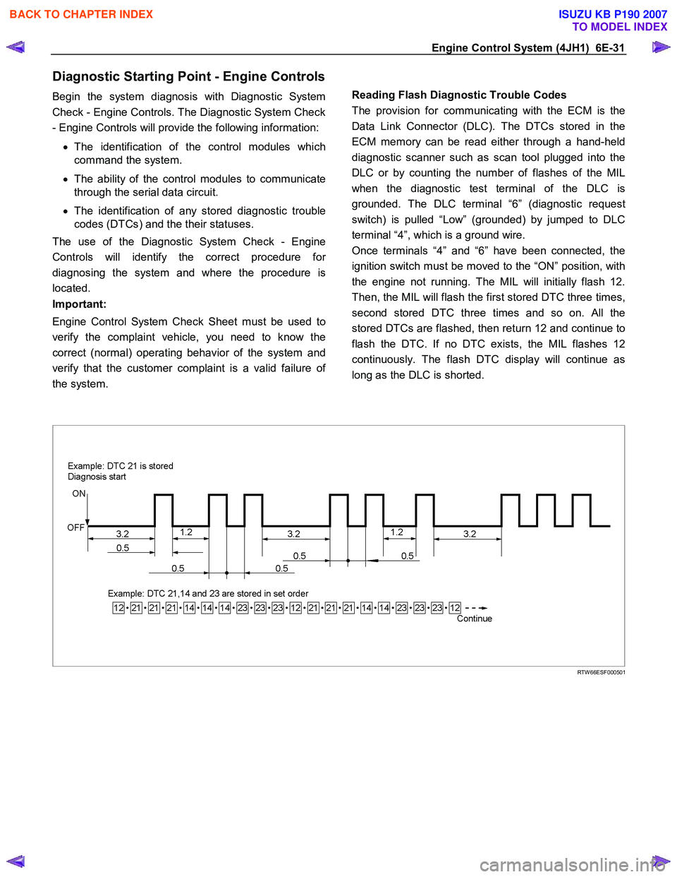
Reading Flash Diagnostic Trouble Codes
The provision for communicating with the ECM is the
Data Link Connector (DLC). The DTCs stored in the
ECM memory can be read either through a hand-held
diagnostic scanner such as scan tool plugged into the
DLC or by counting the number of flashes of the MIL
when the diagnostic test terminal of the DLC is
grounded. The DLC terminal “6” (diagnostic request
switch) is pulled “Low” (grounded) by jumped to DLC
terminal “4”, which is a ground wire.
Once terminals “4” and “6” have been connected, the
ignition switch must be moved to the “ON” position, with
the engine not running. The MIL will initially flash 12.
Then, the MIL will flash the first stored DTC three times,
second stored DTC three times and so on. All the
stored DTCs are flashed, then return 12 and continue to
flash the DTC. If no DTC exists, the MIL flashes 12
continuously. The flash DTC display will continue as
long as the DLC is shorted.
RTW 66ESF000501
BACK TO CHAPTER INDEX
TO MODEL INDEX
ISUZU KB P190 2007
Page 1068 of 6020
6E-34 Engine Control System (4JH1)
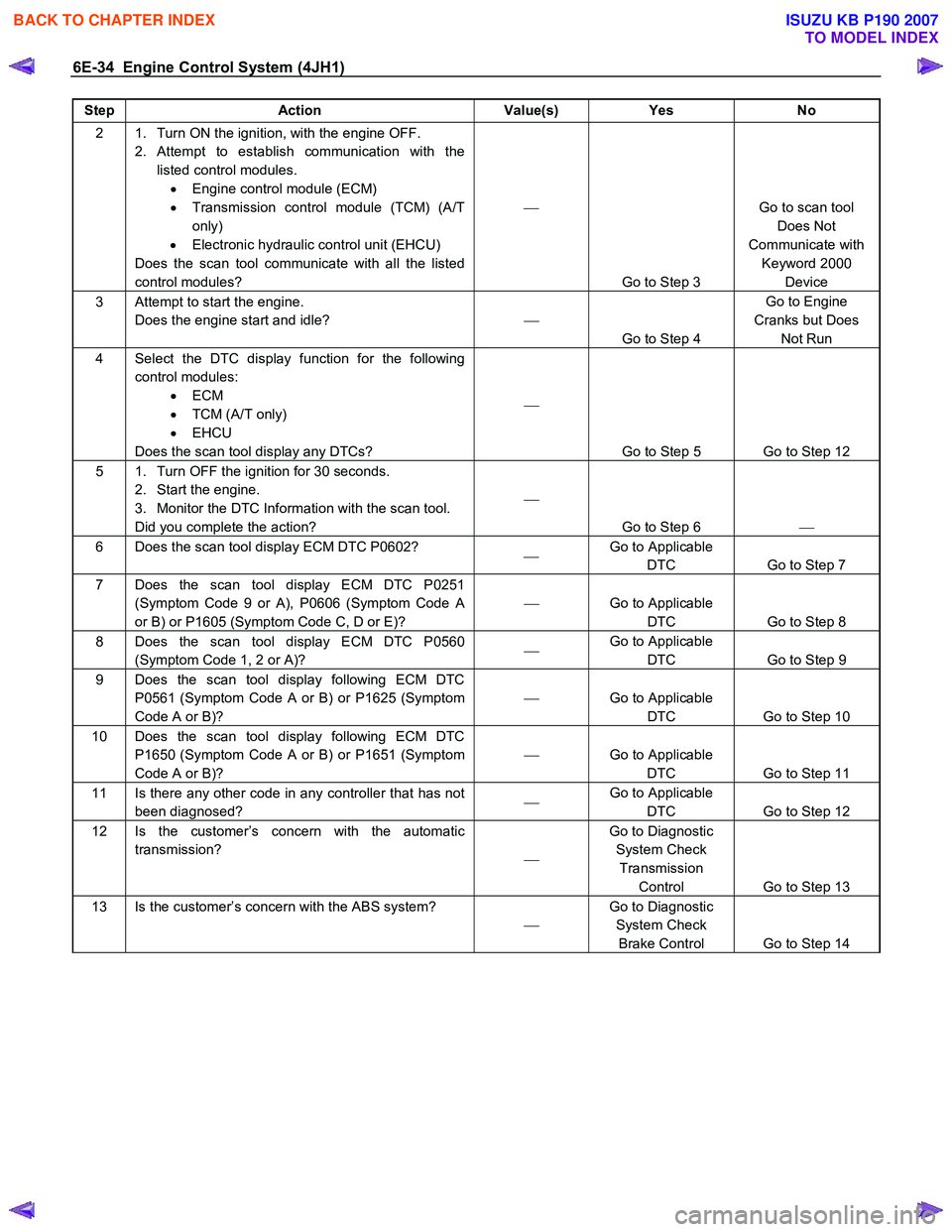
Step Action Value(s) Yes No
2 1. Turn ON the ignition, with the engine OFF.
2. Attempt to establish communication with the listed control modules. • Engine control module (ECM)
• Transmission control module (TCM) (A/T
only)
• Electronic hydraulic control unit (EHCU)
Does the scan tool communicate with all the listed
control modules?
Go to Step 3 Go to scan tool
Does Not
Communicate with Keyword 2000 Device
3 Attempt to start the engine. Does the engine start and idle?
Go to Step 4 Go to Engine
Cranks but Does Not Run
4 Select the DTC display function for the following control modules: • ECM
• TCM (A/T only)
• EHCU
Does the scan tool display any DTCs?
Go to Step 5 Go to Step 12
5 1. Turn OFF the ignition for 30 seconds. 2. Start the engine.
3. Monitor the DTC Information with the scan tool.
Did you complete the action?
Go to Step 6
6 Does the scan tool display ECM DTC P0602?
Go to Applicable
DTC Go to Step 7
7 Does the scan tool display ECM DTC P0251 (Symptom Code 9 or A), P0606 (Symptom Code A
or B) or P1605 (Symptom Code C, D or E)?
Go to Applicable
DTC Go to Step 8
8 Does the scan tool display ECM DTC P0560 (Symptom Code 1, 2 or A)?
Go to Applicable
DTC Go to Step 9
9 Does the scan tool display following ECM DTC
P0561 (Symptom Code A or B) or P1625 (Symptom
Code A or B)?
Go to Applicable
DTC Go to Step 10
10 Does the scan tool display following ECM DTC P1650 (Symptom Code A or B) or P1651 (Symptom
Code A or B)?
Go to Applicable
DTC Go to Step 11
11 Is there any other code in any controller that has not
been diagnosed?
Go to Applicable
DTC Go to Step 12
12 Is the customer’s concern with the automatic
transmission? Go to Diagnostic
System Check Transmission Control Go to Step 13
13 Is the customer’s concern with the ABS system?
Go to Diagnostic
System Check Brake Control Go to Step 14
BACK TO CHAPTER INDEX
TO MODEL INDEX
ISUZU KB P190 2007
Page 1069 of 6020
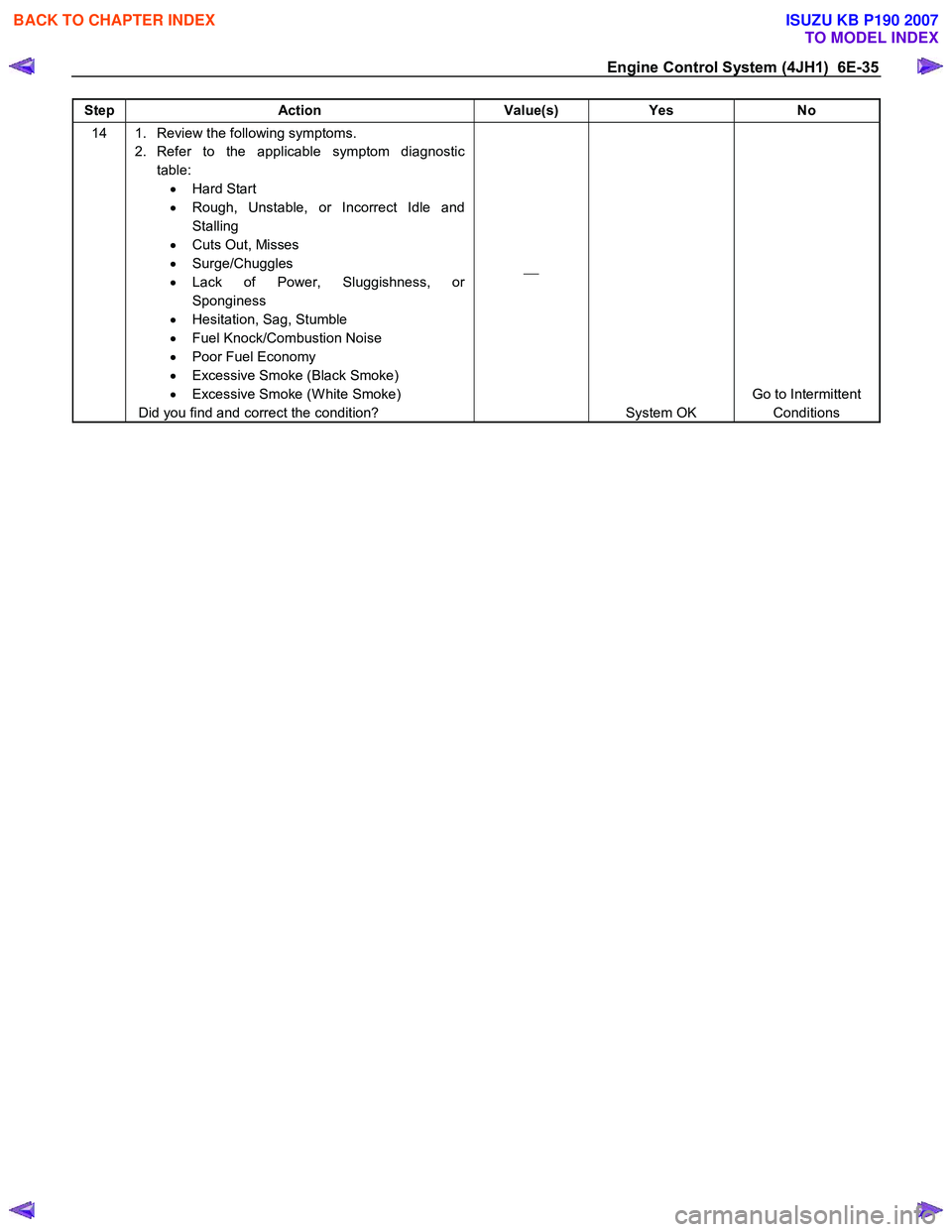
Engine Control System (4JH1) 6E-35
Step Action Value(s) Yes No
14 1. Review the following symptoms.
2. Refer to the applicable symptom diagnostic table: • Hard Start
• Rough, Unstable, or Incorrect Idle and
Stalling
• Cuts Out, Misses
• Surge/Chuggles
• Lack of Power, Sluggishness, or
Sponginess
• Hesitation, Sag, Stumble
• Fuel Knock/Combustion Noise
• Poor Fuel Economy
• Excessive Smoke (Black Smoke)
• Excessive Smoke (W hite Smoke)
Did you find and correct the condition?
System OK Go to Intermittent
Conditions
BACK TO CHAPTER INDEX
TO MODEL INDEX
ISUZU KB P190 2007
Page 1077 of 6020
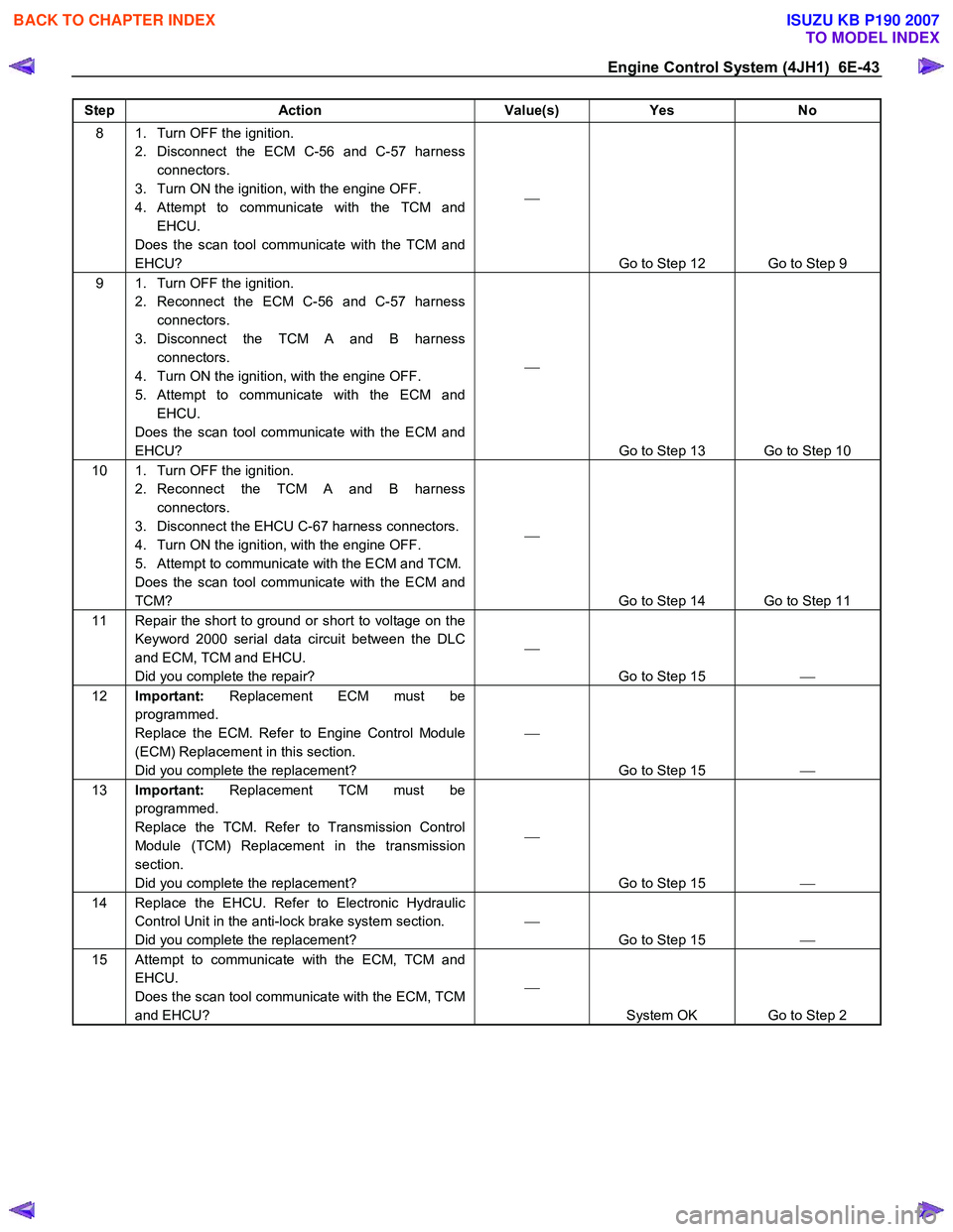
Engine Control System (4JH1) 6E-43
Step Action Value(s) Yes No
8 1. Turn OFF the ignition.
2. Disconnect the ECM C-56 and C-57 harness connectors.
3. Turn ON the ignition, with the engine OFF.
4. Attempt to communicate with the TCM and EHCU.
Does the scan tool communicate with the TCM and
EHCU?
Go to Step 12 Go to Step 9
9 1. Turn OFF the ignition. 2. Reconnect the ECM C-56 and C-57 harness connectors.
3. Disconnect the TCM A and B harness connectors.
4. Turn ON the ignition, with the engine OFF.
5. Attempt to communicate with the ECM and EHCU.
Does the scan tool communicate with the ECM and
EHCU?
Go to Step 13 Go to Step 10
10 1. Turn OFF the ignition. 2. Reconnect the TCM A and B harness connectors.
3. Disconnect the EHCU C-67 harness connectors.
4. Turn ON the ignition, with the engine OFF.
5. Attempt to communicate with the ECM and TCM.
Does the scan tool communicate with the ECM and
TCM?
Go to Step 14 Go to Step 11
11 Repair the short to ground or short to voltage on the Keyword 2000 serial data circuit between the DLC
and ECM, TCM and EHCU.
Did you complete the repair?
Go to Step 15
12 Important: Replacement ECM must be
programmed.
Replace the ECM. Refer to Engine Control Module
(ECM) Replacement in this section.
Did you complete the replacement?
Go to Step 15
13 Important: Replacement TCM must be
programmed.
Replace the TCM. Refer to Transmission Control
Module (TCM) Replacement in the transmission
section.
Did you complete the replacement?
Go to Step 15
14 Replace the EHCU. Refer to Electronic Hydraulic
Control Unit in the anti-lock brake system section.
Did you complete the replacement?
Go to Step 15
15 Attempt to communicate with the ECM, TCM and
EHCU.
Does the scan tool communicate with the ECM, TCM
and EHCU?
System OK Go to Step 2
BACK TO CHAPTER INDEX
TO MODEL INDEX
ISUZU KB P190 2007
Page 1079 of 6020
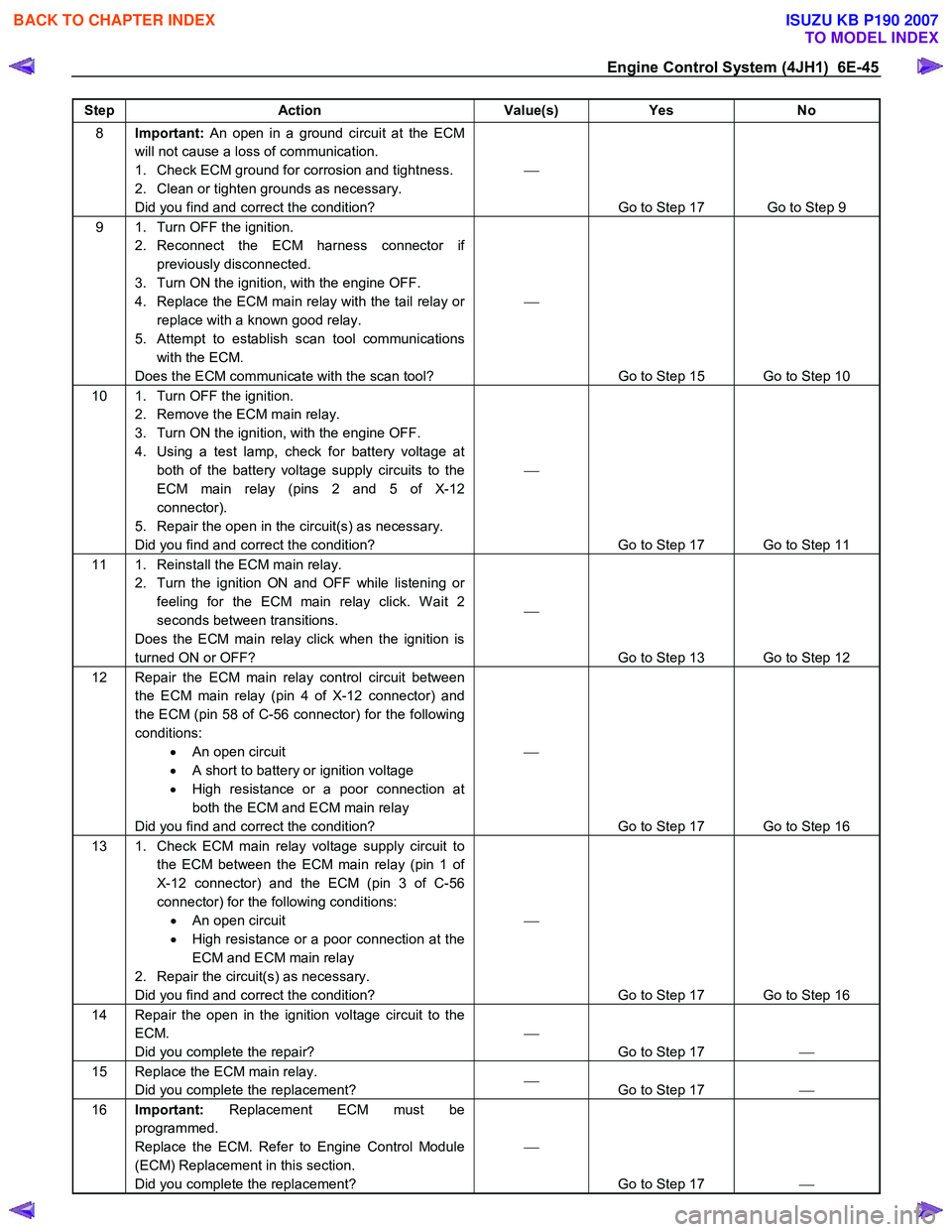
Engine Control System (4JH1) 6E-45
Step Action Value(s) Yes No
8 Important: An open in a ground circuit at the ECM
will not cause a loss of communication.
1. Check ECM ground for corrosion and tightness.
2. Clean or tighten grounds as necessary.
Did you find and correct the condition?
Go to Step 17 Go to Step 9
9 1. Turn OFF the ignition. 2. Reconnect the ECM harness connector if previously disconnected.
3. Turn ON the ignition, with the engine OFF.
4. Replace the ECM main relay with the tail relay or replace with a known good relay.
5. Attempt to establish scan tool communications with the ECM.
Does the ECM communicate with the scan tool?
Go to Step 15 Go to Step 10
10 1. Turn OFF the ignition. 2. Remove the ECM main relay.
3. Turn ON the ignition, with the engine OFF.
4. Using a test lamp, check for battery voltage at both of the battery voltage supply circuits to the
ECM main relay (pins 2 and 5 of X-12
connector).
5. Repair the open in the circuit(s) as necessary.
Did you find and correct the condition?
Go to Step 17 Go to Step 11
11 1. Reinstall the ECM main relay. 2. Turn the ignition ON and OFF while listening or feeling for the ECM main relay click. W ait 2
seconds between transitions.
Does the ECM main relay click when the ignition is
turned ON or OFF?
Go to Step 13 Go to Step 12
12 Repair the ECM main relay control circuit between the ECM main relay (pin 4 of X-12 connector) and
the ECM (pin 58 of C-56 connector) for the following
conditions: • An open circuit
• A short to battery or ignition voltage
• High resistance or a poor connection at
both the ECM and ECM main relay
Did you find and correct the condition?
Go to Step 17 Go to Step 16
13 1. Check ECM main relay voltage supply circuit to the ECM between the ECM main relay (pin 1 of
X-12 connector) and the ECM (pin 3 of C-56
connector) for the following conditions: • An open circuit
• High resistance or a poor connection at the
ECM and ECM main relay
2. Repair the circuit(s) as necessary.
Did you find and correct the condition?
Go to Step 17 Go to Step 16
14 Repair the open in the ignition voltage circuit to the ECM.
Did you complete the repair?
Go to Step 17
15 Replace the ECM main relay.
Did you complete the replacement?
Go to Step 17
16 Important: Replacement ECM must be
programmed.
Replace the ECM. Refer to Engine Control Module
(ECM) Replacement in this section.
Did you complete the replacement?
Go to Step 17
BACK TO CHAPTER INDEX
TO MODEL INDEX
ISUZU KB P190 2007
Page 1080 of 6020
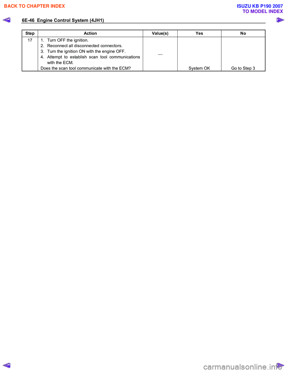
6E-46 Engine Control System (4JH1)
Step Action Value(s) Yes No
17 1. Turn OFF the ignition.
2. Reconnect all disconnected connectors.
3. Turn the ignition ON with the engine OFF.
4. Attempt to establish scan tool communications with the ECM.
Does the scan tool communicate with the ECM?
System OK Go to Step 3
BACK TO CHAPTER INDEX
TO MODEL INDEX
ISUZU KB P190 2007