2007 ISUZU KB P190 check engine
[x] Cancel search: check enginePage 3569 of 6020

Engine Management – V6 – Service Operations Page 6C1-3–45
Ensure the knock sensor is fully seated
before tightening the attaching bolt.
Do not over-tighten the attaching bolt as
incorrect operation of the knock sensor may
result.
2 Reinstall the knock sensor and bolt (1). Align the knock sensor so that it is parallel to the engine oil pan
mounting surface (2), ± 3° (3).
3 Tighten the knock sensor bolt to the correct torque specification.
Knock sensor attaching bolt
torque specification .................................21.0 – 25.0 Nm
4 Road test the vehicle and check for correct operation.
Figure 6C1-3 – 61
2.20 Mass Air Flow Sensor
The intake air temperature (IAT) sensor is part of the mass air flow (MAF) Sensor. For the IAT sensor test procedure
refer to 2.17 Intake Air Temperature Sensor.
Handling Precautions
Under no circumstances should the MAF
sensor retaining screws (1) be loosened or
removed as the MAF will become
unserviceable and will require replacement.
Figure 6C1-3 – 62
Remove
1 Turn the ignition switch off.
BACK TO CHAPTER INDEX
TO MODEL INDEX
ISUZU KB P190 2007
Page 3570 of 6020
Engine Management – V6 – Service Operations Page 6C1-3–46
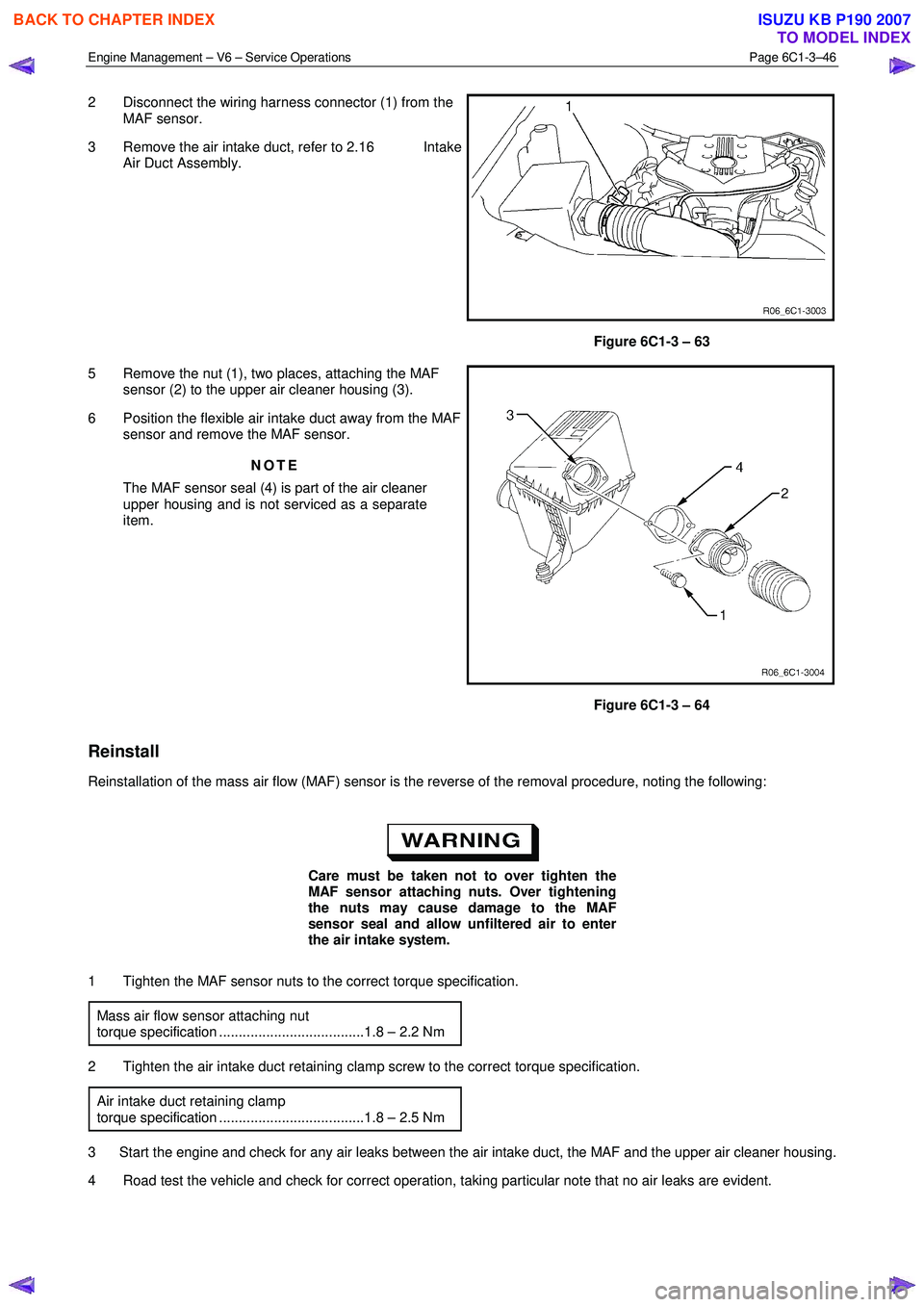
2 Disconnect the wiring harness connector (1) from the
MAF sensor.
3 Remove the air intake duct, refer to 2.16 Intake Air Duct Assembly.
Figure 6C1-3 – 63
5 Remove the nut (1), two places, attaching the MAF sensor (2) to the upper air cleaner housing (3).
6 Position the flexible air intake duct away from the MAF sensor and remove the MAF sensor.
NOTE
The MAF sensor seal (4) is part of the air cleaner
upper housing and is not serviced as a separate
item.
Figure 6C1-3 – 64
Reinstall
Reinstallation of the mass air flow (MAF) sensor is the reverse of the removal procedure, noting the following:
Care must be taken not to over tighten the
MAF sensor attaching nuts. Over tightening
the nuts may cause damage to the MAF
sensor seal and allow unfiltered air to enter
the air intake system.
1 Tighten the MAF sensor nuts to the correct torque specification. Mass air flow sensor attaching nut
torque specification .....................................1.8 – 2.2 Nm
2 Tighten the air intake duct retaining clamp screw to the correct torque specification. Air intake duct retaining clamp
torque specification .....................................1.8 – 2.5 Nm
3 Start the engine and check for any air leaks between the air intake duct, the MAF and the upper air cleaner housing.
4 Road test the vehicle and check for correct operation, taking particular note that no air leaks are evident.
BACK TO CHAPTER INDEX
TO MODEL INDEX
ISUZU KB P190 2007
Page 3571 of 6020
Engine Management – V6 – Service Operations Page 6C1-3–47
2.21 Schrader Valve – Fuel Pressure Gauge
Connection Point
If the Schrader valve is to be removed but not
replaced immediately, it is advisable to
disconnect the battery to avoid possible fuel
discharge if an accidental attempt is made to
start the engine.
Disconnection of the battery affects vehicle
electronic systems. Refer to 6D1-3 Battery –
V6 before disconnecting the battery.
Remove
1 Depressurise the fuel system, refer to 6C Fuel System - V6.
2 Turn the ignition off.
A small amount of fuel may be released when
servicing the fuel pressure test point. To
reduce the chance of personal injury, cover
the fuel pressure test point with a shop towel
to absorb any fuel spillage when the Schrader
valve sealing cap and Schrader valve are
removed. After the procedure, place the towel
in an approved container for disposal.
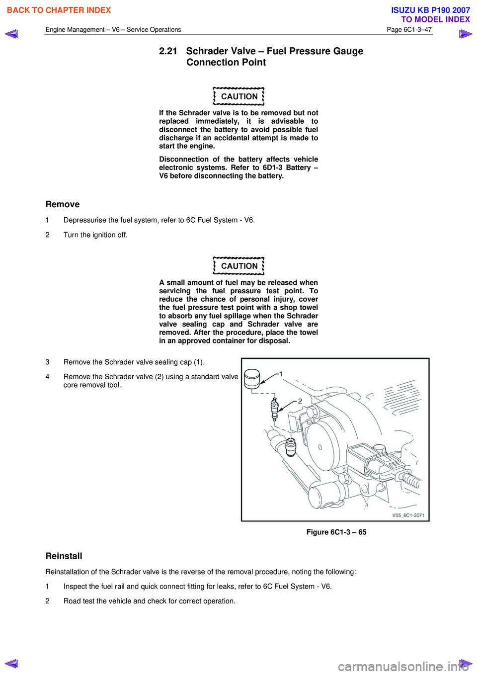
3 Remove the Schrader valve sealing cap (1).
4 Remove the Schrader valve (2) using a standard valve core removal tool.
Figure 6C1-3 – 65
Reinstall
Reinstallation of the Schrader valve is the reverse of the removal procedure, noting the following:
1 Inspect the fuel rail and quick connect fitting for leaks, refer to 6C Fuel System - V6.
2 Road test the vehicle and check for correct operation.
BACK TO CHAPTER INDEX
TO MODEL INDEX
ISUZU KB P190 2007
Page 3573 of 6020
Engine Management – V6 – Service Operations Page 6C1-3–49
1 Replace any plug that has cracked and / or broken insulation or loose electrodes.
2 Inspect the spark plugs for defects. Refer to Analysis of Spark Plug Condition in this Section for identification of the condition of spark plugs.
3 Ensure the threads are clean and in good order.
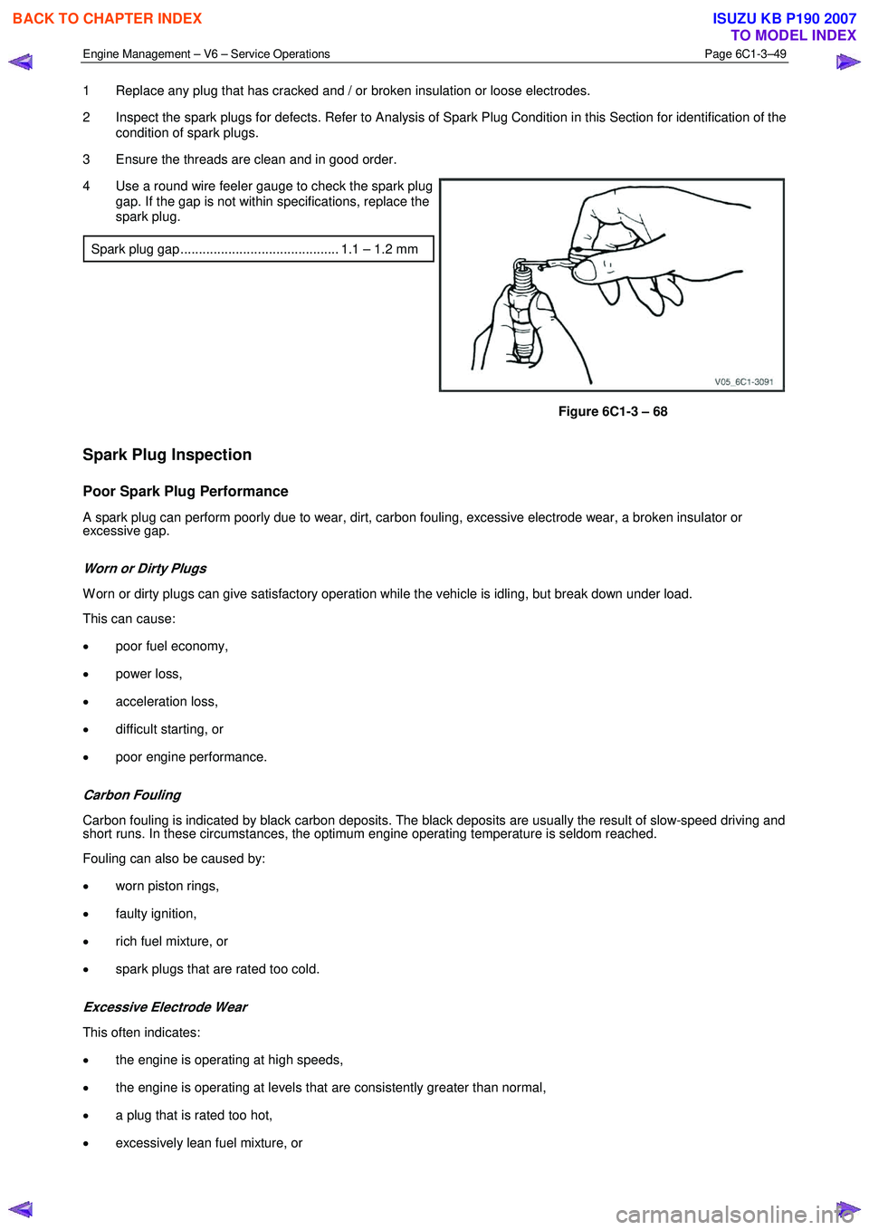
4 Use a round wire feeler gauge to check the spark plug gap. If the gap is not within specifications, replace the
spark plug.
Spark plug gap ........................................... 1.1 – 1.2 mm
Figure 6C1-3 – 68
Spark Plug Inspection
Poor Spark Plug Performance
A spark plug can perform poorly due to wear, dirt, carbon fouling, excessive electrode wear, a broken insulator or
excessive gap.
Worn or Dirty Plugs
W orn or dirty plugs can give satisfactory operation while the vehicle is idling, but break down under load.
This can cause:
• poor fuel economy,
• power loss,
• acceleration loss,
• difficult starting, or
• poor engine performance.
Carbon Fouling
Carbon fouling is indicated by black carbon deposits. The black deposits are usually the result of slow-speed driving and
short runs. In these circumstances, the optimum engine operating temperature is seldom reached.
Fouling can also be caused by:
• worn piston rings,
• faulty ignition,
• rich fuel mixture, or
• spark plugs that are rated too cold.
Excessive Electrode Wear
This often indicates:
• the engine is operating at high speeds,
• the engine is operating at levels that are consistently greater than normal,
• a plug that is rated too hot,
• excessively lean fuel mixture, or
BACK TO CHAPTER INDEX
TO MODEL INDEX
ISUZU KB P190 2007
Page 3576 of 6020
Engine Management – V6 – Service Operations Page 6C1-3–52
Oil Fouled (3)
W et, oily deposits with minor electrode wear possibly due to oil leaking past worn piston rings.
Breaking in a new or recently overhauled engine before the rings are fully seated may also result in this condition.
Deposit Fouling A (4)
Red brown, yellow and white coloured coatings on the insulator tip which are by-products of combustion. They come
from fuel and lubricating oil which generally contain additives. Most powdery deposits have no adverse effect on spark
plug operation, however, they may cause intermittent missing under severe operating conditions.
Deposit Fouling B (5)
Deposits similar to those identified in deposit fouling A (4). These are also by-products of combustion from fuel and
lubricating oil. Excessive valve stem clearances and / or defective intake valve seals allow too much oil to enter the
combustion chamber. The deposits will accumulate on the portion of the spark plug that projects into the chamber and
will be heaviest on the side facing the intake valve. If this condition is only detected in one or two cylinders, check the
valve stem seals.
Deposit Fouling C (6)
Most powdery deposits identified in deposit fouling A (4) have no adverse effect on the operation of the spark plug as
long as they remain powdery.
Under certain conditions of operation however, these deposits melt and form a shiny glaze coating on the insulator.
W hen hot, this acts as a good electrical conductor allowing the current to flow along the deposit instead of sparking
across the gap.
Detonation (7)
Commonly referred to as engine knock or pinging, detonation causes severe shocks inside the combustion chamber
causing damage to parts.
Pre-ignition (8)
Burnt or blistered insulator tip and badly eroded electrodes probably due to the excessive heat.
This is often caused by a cooling system blockage, sticking valves, improperly installed spark plugs or plugs that are the
wrong heat rating (too hot).
Sustained high speed with a heavy load can produce temperatures high enough to cause pre-ignition.
Heat Shock Failure (9)
A rapid increase in spark plug tip temperature under severe operating conditions can cause heat shock and result in
fractured insulators. This is a common cause of broken and cracked insulator tips.
Insufficient Installation Torque (10)
Poor contact between the spark plug and the cylinder head seat.
The lack of proper heat transfer that results from poor seat contact causes overheating of the spark plug. In many cases,
severe damage occurs. Dirty threads in the cylinder head can cause the plug to seize before it is seated.
Ensure the cylinder head and spark plug threads are free of deposits, burrs and scale before installation.
BACK TO CHAPTER INDEX
TO MODEL INDEX
ISUZU KB P190 2007
Page 3577 of 6020
Engine Management – V6 – Service Operations Page 6C1-3–53
Reinstall
Reinstallation of the spark plug is the reverse of the removal procedure, noting the following:
• Discard the spark plug if it has been
dropped.
• Do not use anti-seize compound or similar
lubricant on the spark plug threads.
1 Using a suitably sized rubber tube attached to the spark plug terminal post, hand start each spark plug into the cylinder head thread.
Failure to tighten a spark plug to the correct
torque specification may result in premature
spark plug failure, and / or engine damage.
2 Tighten the spark plug/s to the correct torque specification. Spark plug torque specification ...............16.0 – 20.0 Nm
3 Road test the vehicle and check for correct operation.
2.23 Throttle Body Assembly
Handling Precautions
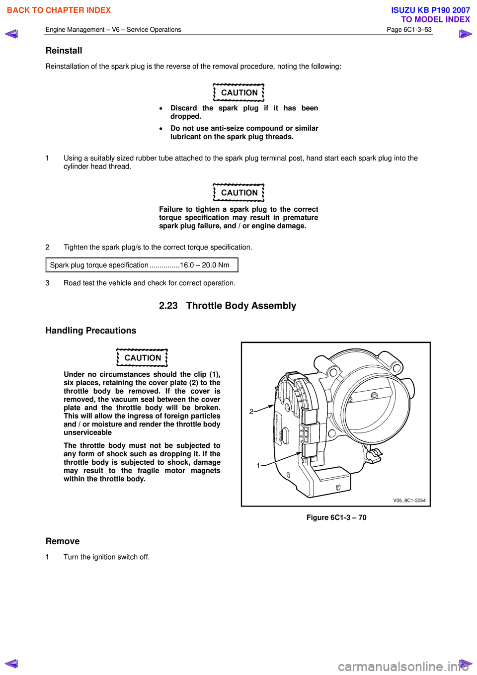
Under no circumstances should the clip (1),
six places, retaining the cover plate (2) to the
throttle body be removed. If the cover is
removed, the vacuum seal between the cover
plate and the throttle body will be broken.
This will allow the ingress of foreign particles
and / or moisture and render the throttle body
unserviceable
The throttle body must not be subjected to
any form of shock such as dropping it. If the
throttle body is subjected to shock, damage
may result to the fragile motor magnets
within the throttle body.
Figure 6C1-3 – 70
Remove
1 Turn the ignition switch off.
BACK TO CHAPTER INDEX
TO MODEL INDEX
ISUZU KB P190 2007
Page 3579 of 6020
Engine Management – V6 – Service Operations Page 6C1-3–55
Inspect
The following throttle body inspection procedure may be carried out with the throttle body installed on the vehicle. Prior to
performing a throttle body on-vehicle inspection:
• Turn the ignition switch off.
• Disconnect the throttle body wiring harness connector. Refer to Remove in this Section.
• Remove the air intake duct, refer to 2.16 Intake Air Duct Assembly.
To avoid serious personal injury, never
attempt to rotate the throttle plate manually
whilst the throttle body harness connector is
connected to the throttle body.
1 Fully open the throttle plate by hand and inspect the throttle body bore and throttle plate for any deposits.
When cleaning / inspecting the throttle body:
• Do not subject the throttle body assembly
to an immersion cleaner or a strong
solvent. Damage to the throttle position
sensor and / or sealed throttle shaft
bearings will result.
• Never use a wire brush or scraper to clean
the throttle body. A wire brush or sharp
tool may damage the throttle body
components.
2 Use a clean shop towel and a spray type hydro-carbon cleaner to clean the throttle body bore and throttle plate. If necessary, use a parts cleaning brush to remove heavy deposits.
3 Inspect the throttle body for a binding throttle plate by fully opening and closing the throttle plate by hand. It should open and close smoothly.
4 Inspect the throttle body for a bent or damaged throttle plate, cracks, corrosion, or distortion in the throttle body housing.
NOTE
The throttle body contains no serviceable parts
and should not be disassembled. If the throttle
body is damaged it must be replaced as an
assembly.
5 If the throttle body is affected by any of the above conditions, it must be replaced.
6 If an on-vehicle throttle body inspection was performed, perform the following:
• Reinstall the air intake duct, refer to 2.16 Intake Air Duct Assembly.
• Reconnect the throttle body wiring harness connector, refer to Reinstall in this Section.
• Road test the vehicle and check for correct operation, taking particular note that no air leaks are evident.
Reinstall
Reinstallation of the throttle body assembly is the reverse of the removal procedure, noting the following:
1 Ensure the throttle body and upper intake manifold mating surfaces are clean and free of foreign material.
2 Install a new throttle body to upper intake manifold gasket.
BACK TO CHAPTER INDEX
TO MODEL INDEX
ISUZU KB P190 2007
Page 3580 of 6020
Engine Management – V6 – Service Operations Page 6C1-3–56
3 Reinstall the throttle body bolts and tighten to the correct torque specification.
Throttle body assembly attaching bolt
torque specification ...................................8.0 – 12.0 Nm
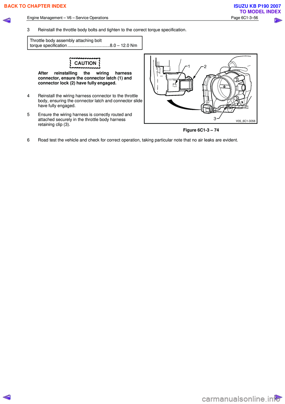
After reinstalling the wiring harness
connector, ensure the connector latch (1) and
connector lock (2) have fully engaged.
4 Reinstall the wiring harness connector to the throttle body, ensuring the connector latch and connector slide
have fully engaged.
5 Ensure the wiring harness is correctly routed and attached securely in the throttle body harness
retaining clip (3).
Figure 6C1-3 – 74
6 Road test the vehicle and check for correct operation, taking particular note that no air leaks are evident.
BACK TO CHAPTER INDEX
TO MODEL INDEX
ISUZU KB P190 2007