Page 4851 of 6020
TRANSFER CASE 7D-21
10. Remove the transfer chain and the front output shaft
from the main shaft.
11. Remove the main shaft snap ring.
12. Remove the speedometer drive gear, the ball
bearings, the retaining ring, and the oil pump
assembly.
13. Remove the sprocket snap ring.
14. Remove the thrust washer, the drive sprocket, the
inside ring, the outside ring, the block ring, and the
rear synchronizer spring.
RTW 37DMF000101
Legend
(8) Thrust W asher
(1) Rear synchronizer spring
(9) Sprocket Snap Ring
(2) Block Ring
(10) Oil Pump ASM
(3) Outside Ring
(11) Oil Pump Retaining Ring
(4) Inside Ring
(12) Retaining Ring
(5) Drive Sprocket
(13) Ball Bearing
(6) Transfer Chain (14) Speedometer Drive Gear
(7) Front Output shaft (15) Main Shaft Snap Ring
BACK TO CHAPTER INDEX
TO MODEL INDEX
ISUZU KB P190 2007
Page 4854 of 6020
7D-24 TRANSFER CASE
Internal Component Disassembly and Reassembly
226R300017
H-L Shift Disassembly
1. Remove the guide roller.
2. Use a vise to compress the H-L shift spring (inside the
assembly)
3. Remove the outer snap ring.
4. Remove the shift block assembly from the shift rod.
5. Use a socket and a vise to compress the shift block
spring (inside the assembly)
6. Remove the inner retaining ring.
7. Remove the collar (rear)
8. Remove the shift block spring.
9. Remove the collar (front)
10. Remove the shift block assembly
11. Remove the spring pin.
12. Remove the shift arm.
Legend
(1) Shift Arm
(2) Shift Block Assembly
(3) Inner Retaining Ring
(4) Collar (Front)
(5) Shift Block Spring
(6) Collar (Rear)
(7) Shift Rod
(8) Outer Snap Ring
(9) Guide Roller
(10) Spring Pin
BACK TO CHAPTER INDEX
TO MODEL INDEX
ISUZU KB P190 2007
Page 4855 of 6020

TRANSFER CASE 7D-25
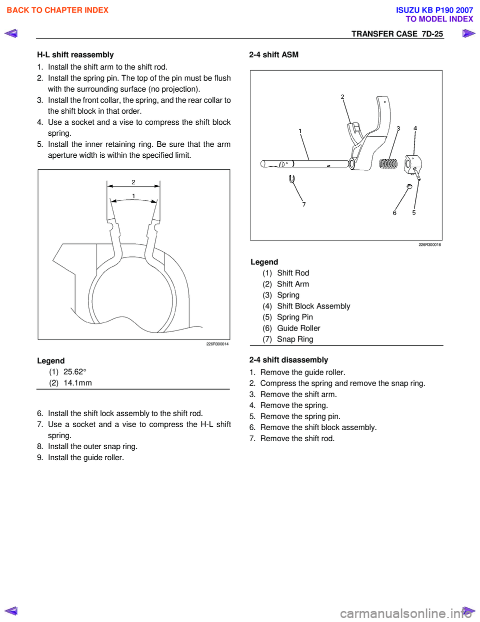
H-L shift reassembly
1. Install the shift arm to the shift rod.
2. Install the spring pin. The top of the pin must be flush
with the surrounding surface (no projection).
3. Install the front collar, the spring, and the rear collar to
the shift block in that order.
4. Use a socket and a vise to compress the shift block
spring.
5. Install the inner retaining ring. Be sure that the arm
aperture width is within the specified limit.
226R300014
6. Install the shift lock assembly to the shift rod.
7. Use a socket and a vise to compress the H-L shift
spring.
8. Install the outer snap ring.
9. Install the guide roller.
2-4 shift ASM
226R300016
2-4 shift disassembly
1. Remove the guide roller.
2. Compress the spring and remove the snap ring.
3. Remove the shift arm.
4. Remove the spring.
5. Remove the spring pin.
6. Remove the shift block assembly.
7. Remove the shift rod.
Legend
(1) 25.62 °
(2) 14.1mm Legend
(1) Shift Rod
(2) Shift Arm
(3) Spring
(4) Shift Block Assembly
(5) Spring Pin
(6) Guide Roller
(7) Snap Ring
BACK TO CHAPTER INDEX
TO MODEL INDEX
ISUZU KB P190 2007
Page 4856 of 6020
7D-26 TRANSFER CASE
2-4 shift reassembly
1. Install the shift block assembly to the shift rod.
2. Install the spring pin. The head of the pin must not
project beyond the surface (1) of the shift block.
226R300015
3. Install the spring.
4. Install the shift arm.
5. Compress the spring and install the snap ring.
6. Install the guide roller.
Oil pump disassembly
1. Remove the clamps securing the screen.
2. Remove the screen.
3. Remove the clamps securing the hose.
4. Remove the hose.
NOTE: To maintain and protect oil pump function, the
pump is constructed so that it cannot be disassembled.
Under no conditions attempt to disassemble the pump.
Oil pump reassembly
1. Tighten the clamps to secure the hose.
2. Tighten the clamps to secure the screen.
NOTE: Be careful in the direction of clamps.
RTW 37DSH000101
Legend
(1) Oil Pump Assembly
(2) Clamp
(3) Hose
(4) Screen Assembly
BACK TO CHAPTER INDEX
TO MODEL INDEX
ISUZU KB P190 2007
Page 4859 of 6020

TRANSFER CASE 7D-29
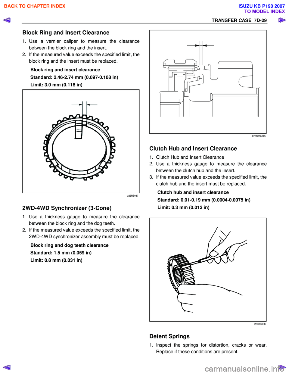
Block Ring and Insert Clearance
1. Use a vernier caliper to measure the clearance
between the block ring and the insert.
2. If the measured value exceeds the specified limit, the
block ring and the insert must be replaced.
Block ring and insert clearance
Standard: 2.46-2.74 mm (0.097-0.108 in)
Limit: 3.0 mm (0.118 in)
226RS037
2WD-4WD Synchronizer (3-Cone)
1. Use a thickness gauge to measure the clearance
between the block ring and the dog teeth.
2. If the measured value exceeds the specified limit, the
2W D-4W D synchronizer assembly must be replaced.
Block ring and dog teeth clearance
Standard: 1.5 mm (0.059 in)
Limit: 0.8 mm (0.031 in)
226R300019
Clutch Hub and Insert Clearance
1. Clutch Hub and Insert Clearance
2. Use a thickness gauge to measure the clearance
between the clutch hub and the insert.
3. If the measured value exceeds the specified limit, the
clutch hub and the insert must be replaced.
Clutch hub and insert clearance
Standard: 0.01-0.19 mm (0.0004-0.0075 in)
Limit: 0.3 mm (0.012 in)
226RS038
Detent Springs
1. Inspect the springs for distortion, cracks or wear.
Replace if these conditions are present.
BACK TO CHAPTER INDEX
TO MODEL INDEX
ISUZU KB P190 2007
Page 4865 of 6020
TRANSFER CASE 7D-35
19. Align the shift shaft splines with the shift drum and
install the shafts to the drum.
RTW 320MF000201
Legend
(1) H-L Sleeve and Shift ASM
(3) Shift Shaft
(2) 2-4 Sleeve ASM with Main Shaft and Shift ASM (4) Shift Drum
NOTE: Be careful in the direction of an assembly.
P1010041/020124
20. Coat the main shaft with oil.
21.
Align the block ring, the outside ring, and the inside
ring with the 2-4 hub assembly and install them.
22. Assemble the sprocket, transfer chain, and front
output shaft.
23. Install the sprocket, transfer chain, and front output
shaft to the main shaft and the transfer case.
BACK TO CHAPTER INDEX
TO MODEL INDEX
ISUZU KB P190 2007
Page 4866 of 6020

7D-36 TRANSFER CASE
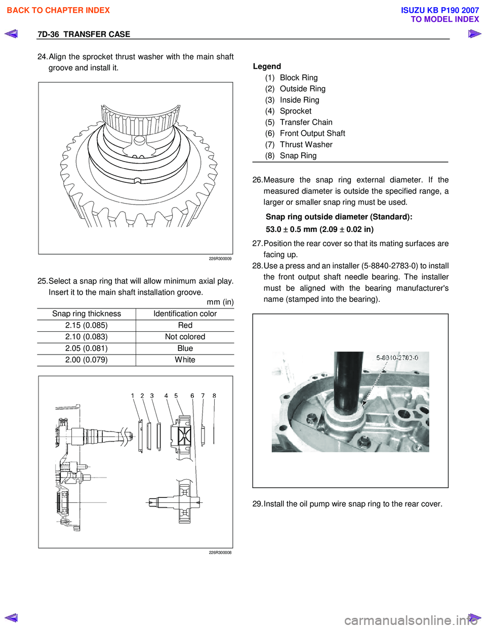
24. Align the sprocket thrust washer with the main shaft
groove and install it.
226R300009
25. Select a snap ring that will allow minimum axial play.
Insert it to the main shaft installation groove.
mm (in)
Snap ring thickness Identification color
2.15 (0.085) Red
2.10 (0.083) Not colored
2.05 (0.081) Blue
2.00 (0.079) White
226R300008
Legend
(1) Block Ring
(2) Outside Ring
(3) Inside Ring
(4) Sprocket
(5) Transfer Chain
(6) Front Output Shaft
(7) Thrust W asher
(8) Snap Ring
26. Measure the snap ring external diameter. If the
measured diameter is outside the specified range, a
larger or smaller snap ring must be used.
Snap ring outside diameter (Standard):
53.0 ±
±±
±
0.5 mm (2.09 ±
±±
±
0.02 in)
27. Position the rear cover so that its mating surfaces are
facing up.
28. Use a press and an installer (5-8840-2783-0) to install
the front output shaft needle bearing. The installe
r
must be aligned with the bearing manufacturer's
name (stamped into the bearing).
29. Install the oil pump wire snap ring to the rear cover.
BACK TO CHAPTER INDEX
TO MODEL INDEX
ISUZU KB P190 2007
Page 4876 of 6020

7D1-2 TRANSFER CONTROL SYSTEM
Service Precaution
WARNING:
THIS VEHICLE HAS A SUPPLEMENTAL RESTRAINT
SYSTEM (SRS). REFER TO THE SRS COMPONENT AND
WIRING LOCATION VIEW IN ORDER TO DETERMINE
WHETHER YOU ARE PERFORMING SERVICE ON OR
NEAR THE SRS COMPONENTS OR THE SRS WIRING.
WHEN YOU ARE PERFORMING SERVICE ON OR NEAR
THE SRS COMPONENTS OR THE SRS WIRING, REFER TO
THE SRS SERVICE INFORMATION. FAILURE TO FOLLOW
WARNINGS COULD RESULT IN POSSIBLE AIR BAG
DEPLOYMENT, PERSONAL INJURY, OR OTHERWISE
UNNECESSARY SRS SYSTEM REPAIRS.
CAUTION:
Always use the correct fastener in the proper location.
When you replace a fastener, use ONLY the exact part
number for that application. ISUZU/GM will call out those
fasteners that require a replacement after removal.
ISUZU/GM will also call out the fasteners that require
thread lockers or thread sealant. UNLESS OTHERWISE
SPECIFIED, do not use supplemental coatings (Paints,
greases, or other corrosion inhibitors) on threaded
fasteners or fastener joint interfaces. Generally, such
coatings adversely affect the fastener torque and the joint
clamping force, and may damage the fastener. When you
install fasteners, use the correct tightening sequence and
specifications. Following these instructions can help you
avoid damage to parts and systems.
BACK TO CHAPTER INDEX
TO MODEL INDEX
ISUZU KB P190 2007