2007 ISUZU KB P190 air condition
[x] Cancel search: air conditionPage 3754 of 6020
Exhaust System – V6 Page 6F – 6
• Faulty operation or performance of any system or component being repaired,
• Damage to any system or components which depend on the proper operation of the system or component being
repaired,
• Faulty operation or performance of any systems or components which depend on the proper operation or
performance of the system or component under repair,
• Damage to fasteners, basic tools or special tools and / or
• Leakage of coolant, lubricant or other vital fluids.
NOTE defined
A NOTE statement immediately precedes or follows an operating procedure, maintenance practice or condition that
requires highlighting. A NOTE statement also emphasises necessary characteristics of a diagnostic or repair procedure.
A NOTE statement is designed to:
• Clarify a procedure,
• Present additional information for accomplishing a procedure,
• Give insight into the reasons for performing a procedure in the recommended manner, and / or
• Present information that gives the technician the benefit of past experience in accomplishing a procedure with
greater ease.
BACK TO CHAPTER INDEX
TO MODEL INDEX
ISUZU KB P190 2007
Page 3763 of 6020
Automatic Transmission – 4L60E – General Information Page 7C1–3
1 Section Descriptions
Service information for the Hydra-matic 4L60E Automatic transmission has been divided into five Sections to assist the
technician to quickly locate the correct service, maintenance and diagnostic information.
The following provides a brief outline of each of the Sections.
• 7C1 Automatic Transmission – 4L60E – General Information
• 7C2 Automatic Transmission – 4L60E – Electrical Diagnosis
• 7C3 Automatic Transmission – 4L60E – Hydraulic and Mechanical Diagnosis
• 7C4 Automatic Transmission – 4L60E – On-vehicle Servicing
The following provides a brief outline of each of the Sections.
1.1 WARNINGS, CAUTIONS and NOTES
This Section contains various W ARNINGS, CAUTIONS and NOTE statements that you must observe carefully to reduce
the risk of death or injury during service, repair procedures or vehicle operation. Incorrect service or repair procedures
may damage the vehicle or cause operational faults. W ARNINGS, CAUTION and NOTE statements are not exhaustive.
GM HOLDEN LTD can not possibly warn of all the potentially hazardous consequences of failure to follow these
instructions.
Definition of WARNING, CAUTION and NOTE Statements
Diagnosis and repair procedures in this Section contain both general and specific W ARNING, CAUTION and NOTE
statements. GM HOLDEN LTD is dedicated to the presentation of service information that helps the technician to
diagnose and repair the systems necessary for proper operation of the vehicle. Certain procedures may present a hazard
to the technician if they are not followed in the recommended manner. W ARNING, CAUTION and NOTE statements are
designed to help prevent these hazards from occurring, but not all hazards can be foreseen.
WARNING Defined
A W ARNING statement immediately precedes an operating procedure or maintenance practice which, if not correctly
followed, could result in death or injury. A WARNING statement alerts you to take necessary action or not to take a
prohibited action. If a W ARNING statement is ignored, the following consequences may occur:
• Death or injury to the technician or other personnel working on the vehicle,
• Death or injury to other people in or near the workplace area, and / or
• Death or injury to the driver / or passenger(s) of the vehicle or other people, if the vehicle has been improperly
repaired.
CAUTION Defined
A CAUTION statement immediately precedes an operating procedure or maintenance practice which, if not correctly
followed, could result in damage to or destruction of equipment, or corruption of data. If a CAUTION statement is ignored,
the following consequences may occur:
• Damage to the vehicle,
• Unnecessary vehicle repairs or component replacement,
• Faulty operation or performance of any system or component being repaired,
• Damage to any system or components which depend on the proper operation of the system or component being
repaired,
• Faulty operation or performance of any systems or components which depend on the proper operation or
performance of the system or component under repair,
• Damage to fasteners, basic tools or special tools and / or
• Leakage of coolant, lubricant or other vital fluids.
NOTE Defined
A NOTE statement immediately precedes or follows an operating procedure, maintenance practice or condition that
requires highlighting. A NOTE statement also emphasises necessary characteristics of a diagnostic or repair procedure.
A NOTE statement is designed to:
• Clarify a procedure,
• Present additional information for accomplishing a procedure,
• Give insight into the reasons for performing a procedure in the recommended manner, and / or
• Present information that gives the technician the benefit of past experience in accomplishing a procedure with
greater ease.
BACK TO CHAPTER INDEX
TO MODEL INDEX
ISUZU KB P190 2007
Page 3774 of 6020
Automatic Transmission – 4L60E – General Information Page 7C1–14
4.4 Abbreviations
Abbreviation Definition
2W D Two W heel Drive.
AC Alternating Current
A/C Air Conditioning
AFL Actuator Feed Limit
4W D Four W heel Drive
DC Direct Current
D.C Duty Cycle
DLC Diagnostic Link Connector
DTC Diagnostic Trouble Code
ECM Engine Control Module
ECT Sensor Engine Coolant Temperature Sensor.
ETC Electronic Throttle Control
N.C Normally Closed
N.O. Normally Open
PCS Pressure Control Solenoid (or Force Motor)
PIM Powertrain Interface Module
PW M Pulse W idth Modulated
RWD Rear Wheel Drive.
TCC Torque Converter Clutch.
TCM Transmission Control Module
TFP Switch Transmission Fluid Pressure Manual Valve Position Switch
TFT Transmission Fluid Temperature Sensor.
TP Sensor Throttle Position Sensor.
VS Sensor Vehicle Speed Sensor.
BACK TO CHAPTER INDEX
TO MODEL INDEX
ISUZU KB P190 2007
Page 3775 of 6020

Automatic Transmission – 4L60E – General Information Page 7C1–15
5 Service Notes
In the interests of safety to personnel, equipment and to the vehicle and its components, read and adhere to the following
notes whenever servicing operations are to be carried out on the Hydra-matic 4L60E automatic transmission. In addition,
some of this information also refers to sound workshop practices and, to achieve the design life of affected components.
Fasteners
• Always reinstall fasteners in the same locations as they were removed.
• If a fastener requires replacement, always use a part of the correct part number or of equal size and strength or
stronger.
General Workshop Practice
• Keep work area and tools clean.
• To avoid unnecessary contamination, always clean the exterior of the transmission before removing any parts.
• Do not use wiping cloths or rags because of the risk of lint being trapped in the transmission.
• Do not use solvents on:
• neoprene seals,
• composition faced clutch plates, or
• thrust washers.
• Always wear eye protection when using compressed air.
• Blow out all passages with compressed air. Only probe small passages with soft, thin wire.
• Handle parts with care to avoid nicks and scratches.
• Do not remove Teflon oil seal rings unless damaged or performing a complete overhaul.
• Expand internal snap rings and compress external snap rings to maximise retention and security.
• Lubricate all internal parts with transmission fluid (only use Dexron® III), as they are being installed.
• When installing cap screws into aluminium castings:
• always use a torque wrench and
• stripped or damaged threads in aluminium castings may be reconditioned by using commercially available
thread inserts.
• Once removed, replace all gaskets, seals and O-rings with new parts.
• Always use seal protectors where indicated and do not use gasket cement or sealant on any joined face unless
specified to do so.
BACK TO CHAPTER INDEX
TO MODEL INDEX
ISUZU KB P190 2007
Page 3797 of 6020
Automatic Transmission – 4L60E – Electrical Diagnosis Page 7C2–11
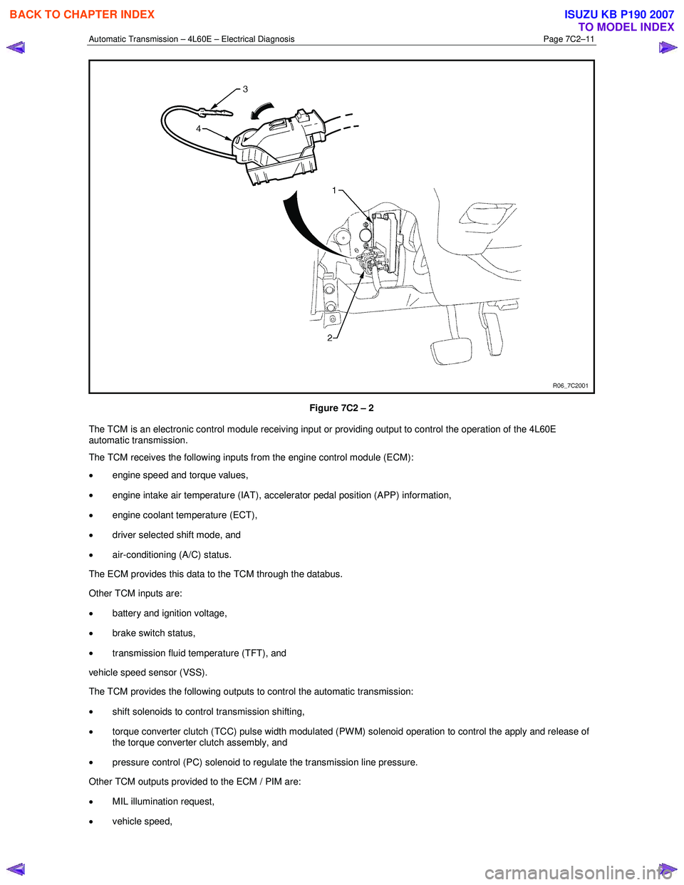
Figure 7C2 – 2
The TCM is an electronic control module receiving input or providing output to control the operation of the 4L60E
automatic transmission.
The TCM receives the following inputs from the engine control module (ECM):
• engine speed and torque values,
• engine intake air temperature (IAT), accelerator pedal position (APP) information,
• engine coolant temperature (ECT),
• driver selected shift mode, and
• air-conditioning (A/C) status.
The ECM provides this data to the TCM through the databus.
Other TCM inputs are:
• battery and ignition voltage,
• brake switch status,
• transmission fluid temperature (TFT), and
vehicle speed sensor (VSS).
The TCM provides the following outputs to control the automatic transmission:
• shift solenoids to control transmission shifting,
• torque converter clutch (TCC) pulse width modulated (PW M) solenoid operation to control the apply and release of
the torque converter clutch assembly, and
• pressure control (PC) solenoid to regulate the transmission line pressure.
Other TCM outputs provided to the ECM / PIM are:
• MIL illumination request,
• vehicle speed,
BACK TO CHAPTER INDEX
TO MODEL INDEX
ISUZU KB P190 2007
Page 3808 of 6020
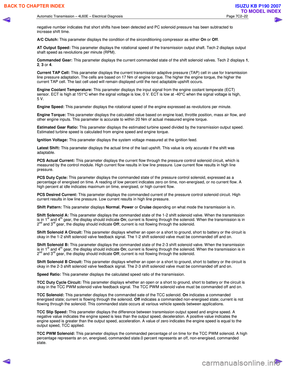
Automatic Transmission – 4L60E – Electrical Diagnosis Page 7C2–22
negative number indicates that short shifts have been detected and PC solenoid pressure has been subtracted to
increase shift time.
A/C Clutch: This parameter displays the condition of the sirconditioning compressor as either On or Off .
AT Output Speed: This parameter displays the rotational speed of the transmission output shaft. Tech 2 displays output
shaft speed as revolutions per minute (RPM).
Commanded Gear: This parameter displays the current commanded state of the shift solenoid valves. Tech 2 displays 1,
2 , 3 or 4.
Current TAP Cell: This parameter displays the current transmission adaptive pressure (TAP) cell in use for transmission
line pressure adaptation. The cells are based on 17 Nm of engine torque. The higher the engine torque, the higher the
current TAP cell. The last cell used will remain displayed until the next adaptable upshift occurs.
Engine Coolant Temperature: This parameter displays the input signal from the engine coolant temperate (ECT)
sensor. ECT is high at 151°C when the signal voltage is low, 0 V. ECT is low at -40°C when the signal voltage is high,
5 V.
Engine Speed: This parameter displays the rotational speed of the engine expressed as revolutions per minute.
Engine Torque: This parameter displays the calculated value based on engine load, throttle position, mass air flow, and
other engine inputs. This parameter is accurate to within 20 Nm of actual measured engine torque.
Estimated Gear Ratio: This parameter displays the estimated turbine speed divided by the transmission output speed.
Estimated turbine speed is calculated from engine speed and engine torque.
Ignition Voltage: This parameter displays the
system voltage measured at the ignition feed.
Latest Shift: This parameter displays the actual time of the last upshift. This value is only accurate if the shift was
adaptable.
PCS Actual Current: This parameter displays the current flow through the pressure control solenoid circuit, which is
measured by the control module. High current flow results in low line pressure. Low current flow results in high line
pressure.
PCS Duty Cycle: This parameter displays the commanded state of the pressure control solenoid, expressed as a
percentage of energised on time. A reading of low percent indicates zero on time, non-energised, or no current flow. A
high percent at idle indicates maximum on time, energised, or high current flow.
PCS Desired Current: This parameter displays the commanded current of the pressure control solenoid circuit. High
current results in low line pressure. Low current results in high line pressure.
Shift Pattern: This parameter displays Normal, Power or Cruise depending on what mode the transmission is in.
Shift Solenoid A: This parameter displays the commanded state of the 1-2 shift solenoid valve. W hen the transmission
is in 1
st and 4th gear, the display should indicate On; current is flowing through the solenoid. When the transmission is in
2nd and 3rd gear, the display should indicate Off; current is not flowing through the solenoid.
Shift Solenoid A Circuit: This parameter displays whether an open or a short to ground, short to battery or the circuit is
okay in the 1-2 shift solenoid valve feedback signal. The 1-2 shift solenoid valve must be commanded off and on.
Shift Solenoid B: This parameter displays the commanded state of the 2-3 shift solenoid valve. W hen the transmission
is in 1
st and 4th gear, the display should indicate On; current is flowing through the solenoid. When the transmission is in
2nd and 3rd gear, the display should indicate Off; current is not flowing through the solenoid.
Shift Solenoid B Circuit: This parameter displays whether an open or a short to ground, short to battery or the circuit is
okay in the 2-3 shift solenoid valve feedback signal. The 2-3 shift solenoid valve must be commanded off and on.
Speed Ratio: This parameter displays the calculated speed ratio of the transmission.
TCC Duty Cycle Circuit: This parameter displays whether an open or a short to ground, short to battery or the circuit is
okay in the TCC PW M solenoid valve feedback signal. The TCC PW M solenoid valve must be commanded off and on.
TCC Solenoid: This parameter displays the commanded sate of the TCC solenoid. On indicates a commanded
energised state; current is flowing through the solenoid. Off indicates a commanded non-energised state; current is not
flowing through the solenoid. This commanded state occurs at various vehicle speeds between applications.
TCC Slip Speed: This parameter displays the difference between transmission output speed and engine speed. A
negative value indicates the engine speed is less than the output speed, deceleration. A positive value indicates the
engine speed is greater than the output speed, acceleration. A value of zero indicates the engine speed is equal to the
output speed, TCC applied.
TCC PWM Solenoid: This parameter displays the commanded percentage of on time for the TCC PWM solenoid. A high
percentage represents an on, energised, commanded state.0 percent represents an off, non-energised, commanded
state.
BACK TO CHAPTER INDEX
TO MODEL INDEX
ISUZU KB P190 2007
Page 3820 of 6020
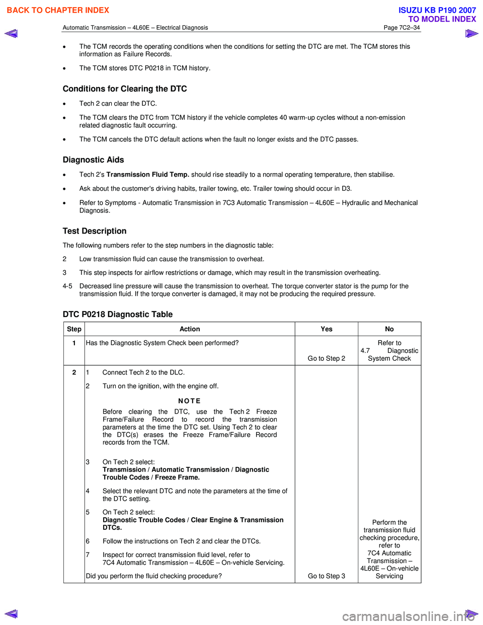
Automatic Transmission – 4L60E – Electrical Diagnosis Page 7C2–34
• The TCM records the operating conditions when the conditions for setting the DTC are met. The TCM stores this
information as Failure Records.
• The TCM stores DTC P0218 in TCM history.
Conditions for Clearing the DTC
• Tech 2 can clear the DTC.
• The TCM clears the DTC from TCM history if the vehicle completes 40 warm-up cycles without a non-emission
related diagnostic fault occurring.
• The TCM cancels the DTC default actions when the fault no longer exists and the DTC passes.
Diagnostic Aids
• Tech 2’s Transmission Fluid Temp. should rise steadily to a normal operating temperature, then stabilise.
• Ask about the customer's driving habits, trailer towing, etc. Trailer towing should occur in D3.
• Refer to Symptoms - Automatic Transmission in 7C3 Automatic Transmission – 4L60E – Hydraulic and Mechanical
Diagnosis.
Test Description
The following numbers refer to the step numbers in the diagnostic table:
2 Low transmission fluid can cause the transmission to overheat.
3 This step inspects for airflow restrictions or damage, which may result in the transmission overheating.
4-5 Decreased line pressure will cause the transmission to overheat. The torque converter stator is the pump for the transmission fluid. If the torque converter is damaged, it may not be producing the required pressure.
DTC P0218 Diagnostic Table
Step Action Yes No
1 Has the Diagnostic System Check been performed?
Go to Step 2 Refer to
4.7 Diagnostic System Check
2 1 Connect Tech 2 to the DLC.
2 Turn on the ignition, with the engine off.
NOTE
Before clearing the DTC, use the Tech 2 Freeze
Frame/Failure Record to record the transmission
parameters at the time the DTC set. Using Tech 2 to clear
the DTC(s) erases the Freeze Frame/Failure Record
records from the TCM.
3 On Tech 2 select: Transmission / Automatic Transmission / Diagnostic
Trouble Codes / Freeze Frame.
4 Select the relevant DTC and note the parameters at the time of the DTC setting.
5 On Tech 2 select:
Diagnostic Trouble Codes / Clear Engine & Transmission
DTCs.
6 Follow the instructions on Tech 2 and clear the DTCs.
7 Inspect for correct transmission fluid level, refer to 7C4 Automatic Transmission – 4L60E – On-vehicle Servicing.
Did you perform the fluid checking procedure? Go to Step 3 Perform the
transmission fluid
checking procedure, refer to
7C4 Automatic
Transmission –
4L60E – On-vehicle Servicing
BACK TO CHAPTER INDEX
TO MODEL INDEX
ISUZU KB P190 2007
Page 3821 of 6020
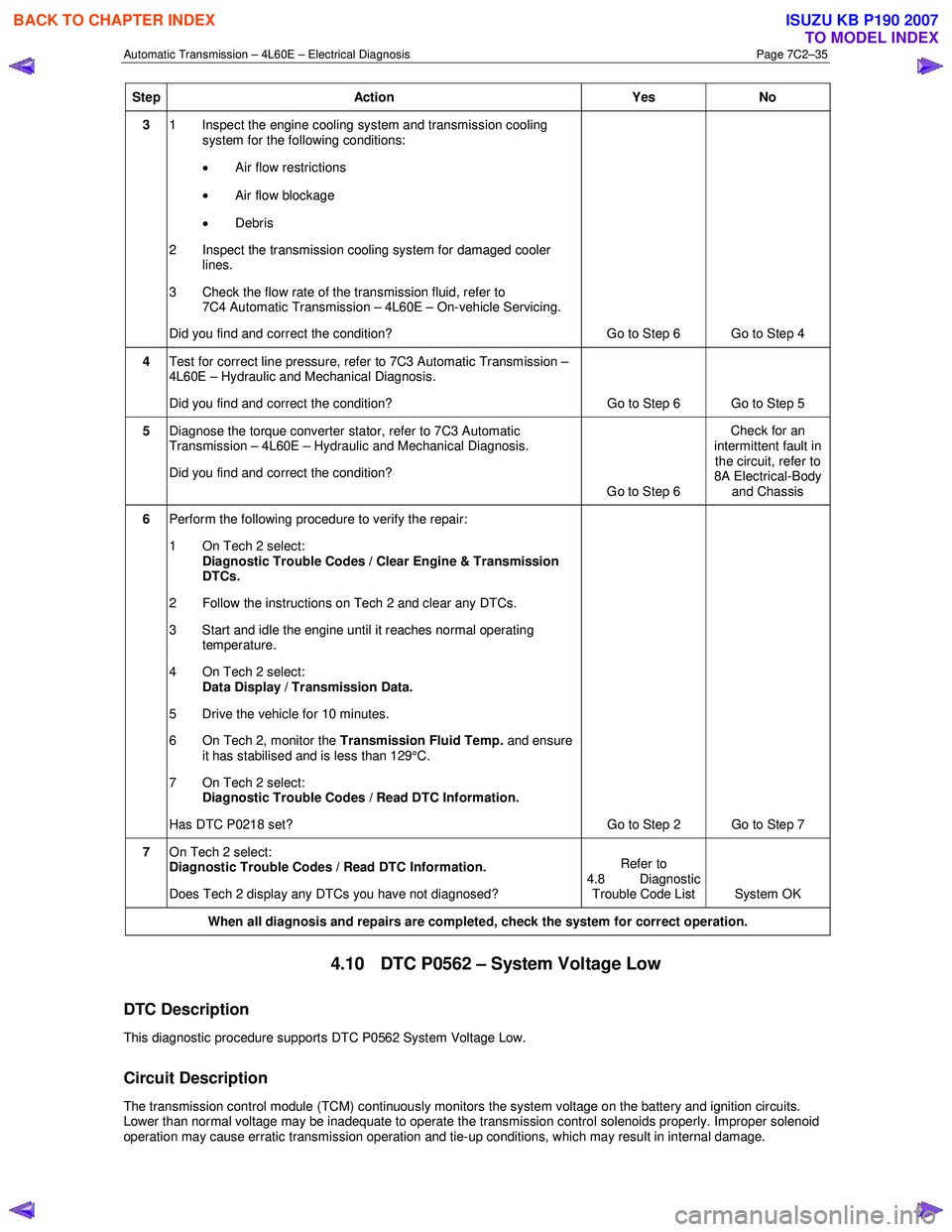
Automatic Transmission – 4L60E – Electrical Diagnosis Page 7C2–35
Step Action Yes No
3 1 Inspect the engine cooling system and transmission cooling
system for the following conditions:
• Air flow restrictions
• Air flow blockage
• Debris
2 Inspect the transmission cooling system for damaged cooler lines.
3 Check the flow rate of the transmission fluid, refer to 7C4 Automatic Transmission – 4L60E – On-vehicle Servicing.
Did you find and correct the condition? Go to Step 6 Go to Step 4
4 Test for correct line pressure, refer to 7C3 Automatic Transmission –
4L60E – Hydraulic and Mechanical Diagnosis.
Did you find and correct the condition? Go to Step 6 Go to Step 5
5 Diagnose the torque converter stator, refer to 7C3 Automatic
Transmission – 4L60E – Hydraulic and Mechanical Diagnosis.
Did you find and correct the condition? Go to Step 6 Check for an
intermittent fault in the circuit, refer to
8A Electrical-Body
and Chassis
6 Perform the following procedure to verify the repair:
1 On Tech 2 select: Diagnostic Trouble Codes / Clear Engine & Transmission
DTCs.
2 Follow the instructions on Tech 2 and clear any DTCs.
3 Start and idle the engine until it reaches normal operating temperature.
4 On Tech 2 select: Data Display / Transmission Data.
5 Drive the vehicle for 10 minutes.
6 On Tech 2, monitor the Transmission Fluid Temp. and ensure
it has stabilised and is less than 129°C.
7 On Tech 2 select:
Diagnostic Trouble Codes / Read DTC Information.
Has DTC P0218 set? Go to Step 2 Go to Step 7
7 On Tech 2 select:
Diagnostic Trouble Codes / Read DTC Information.
Does Tech 2 display any DTCs you have not diagnosed? Refer to
4.8 Diagnostic Trouble Code List System OK
When all diagnosis and repairs are completed, check the
system for correct operation.
4.10 DTC P0562 – System Voltage Low
DTC Description
This diagnostic procedure supports DTC P0562 System Voltage Low.
Circuit Description
The transmission control module (TCM) continuously monitors the system voltage on the battery and ignition circuits.
Lower than normal voltage may be inadequate to operate the transmission control solenoids properly. Improper solenoid
operation may cause erratic transmission operation and tie-up conditions, which may result in internal damage.
BACK TO CHAPTER INDEX
TO MODEL INDEX
ISUZU KB P190 2007