2007 ISUZU KB P190 check engine
[x] Cancel search: check enginePage 3351 of 6020
Engine Management – V6 – Diagnostics Page 6C1-2–73
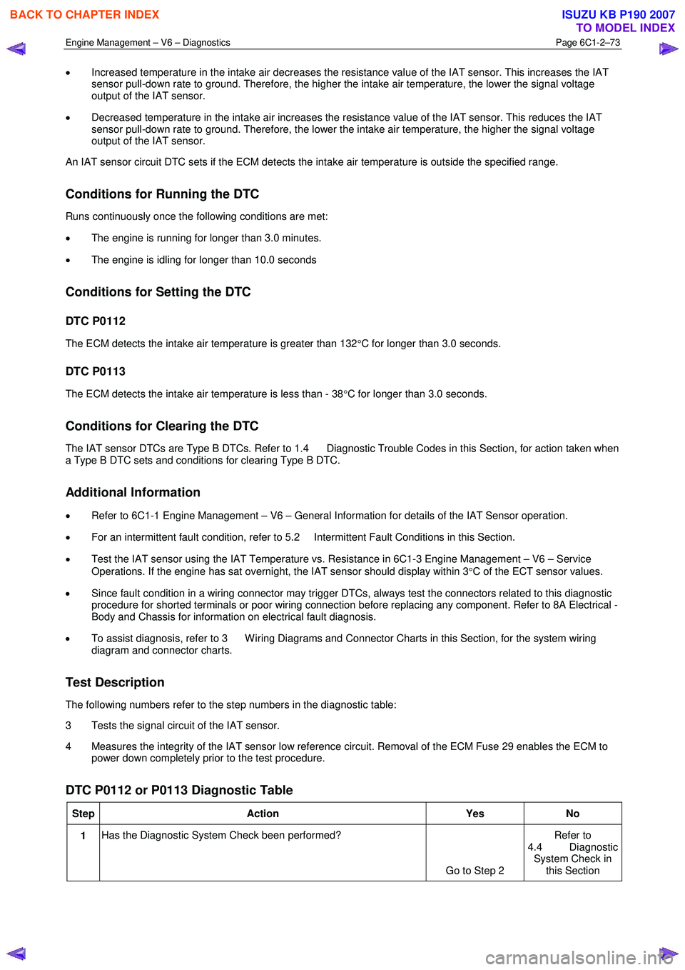
• Increased temperature in the intake air decreases the resistance value of the IAT sensor. This increases the IAT
sensor pull-down rate to ground. Therefore, the higher the intake air temperature, the lower the signal voltage
output of the IAT sensor.
• Decreased temperature in the intake air increases the resistance value of the IAT sensor. This reduces the IAT
sensor pull-down rate to ground. Therefore, the lower the intake air temperature, the higher the signal voltage
output of the IAT sensor.
An IAT sensor circuit DTC sets if the ECM detects the intake air temperature is outside the specified range.
Conditions for Running the DTC
Runs continuously once the following conditions are met:
• The engine is running for longer than 3.0 minutes.
• The engine is idling for longer than 10.0 seconds
Conditions for Setting the DTC
DTC P0112
The ECM detects the intake air temperature is greater than 132 °C for longer than 3.0 seconds.
DTC P0113
The ECM detects the intake air temperature is less than - 38 °C for longer than 3.0 seconds.
Conditions for Clearing the DTC
The IAT sensor DTCs are Type B DTCs. Refer to 1.4 Diagnostic Trouble Codes in this Section, for action taken when
a Type B DTC sets and conditions for clearing Type B DTC.
Additional Information
• Refer to 6C1-1 Engine Management – V6 – General Information for details of the IAT Sensor operation.
• For an intermittent fault condition, refer to 5.2 Intermittent Fault Conditions in this Section.
• Test the IAT sensor using the IAT Temperature vs. Resistance in 6C1-3 Engine Management – V6 – Service
Operations. If the engine has sat overnight, the IAT sensor should display within 3 °C of the ECT sensor values.
• Since fault condition in a wiring connector may trigger DTCs, always test the connectors related to this diagnostic
procedure for shorted terminals or poor wiring connection before replacing any component. Refer to 8A Electrical -
Body and Chassis for information on electrical fault diagnosis.
• To assist diagnosis, refer to 3 W iring Diagrams and Connector Charts in this Section, for the system wiring
diagram and connector charts.
Test Description
The following numbers refer to the step numbers in the diagnostic table:
3 Tests the signal circuit of the IAT sensor.
4 Measures the integrity of the IAT sensor low reference circuit. Removal of the ECM Fuse 29 enables the ECM to power down completely prior to the test procedure.
DTC P0112 or P0113 Diagnostic Table
Step Action Yes No
1 Has the Diagnostic System Check been performed?
Go to Step 2 Refer to
4.4 Diagnostic System Check in this Section
BACK TO CHAPTER INDEX
TO MODEL INDEX
ISUZU KB P190 2007
Page 3353 of 6020
Engine Management – V6 – Diagnostics Page 6C1-2–75
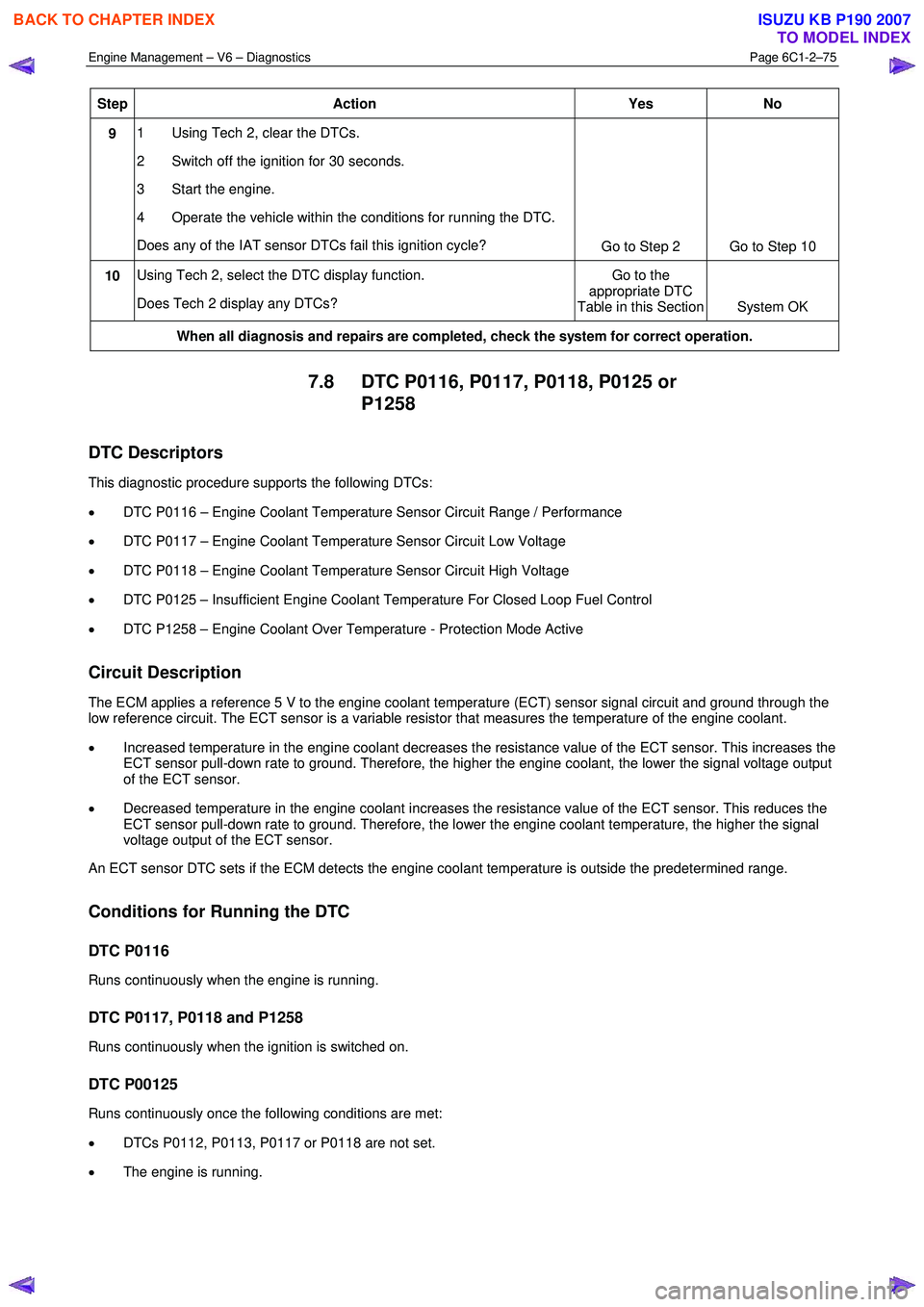
Step Action Yes No
9 1 Using Tech 2, clear the DTCs.
2 Switch off the ignition for 30 seconds.
3 Start the engine.
4 Operate the vehicle within the conditions for running the DTC.
Does any of the IAT sensor DTCs fail this ignition cycle? Go to Step 2 Go to Step 10
10 Using Tech 2, select the DTC display function.
Does Tech 2 display any DTCs? Go to the
appropriate DTC
Table in this Section System OK
When all diagnosis and repairs are completed, check the system for correct operation.
7.8 DTC P0116, P0117, P0118, P0125 or
P1258
DTC Descriptors
This diagnostic procedure supports the following DTCs:
• DTC P0116 – Engine Coolant Temperature Sensor Circuit Range / Performance
• DTC P0117 – Engine Coolant Temperature Sensor Circuit Low Voltage
• DTC P0118 – Engine Coolant Temperature Sensor Circuit High Voltage
• DTC P0125 – Insufficient Engine Coolant Temperature For Closed Loop Fuel Control
• DTC P1258 – Engine Coolant Over Temperature - Protection Mode Active
Circuit Description
The ECM applies a reference 5 V to the engine coolant temperature (ECT) sensor signal circuit and ground through the
low reference circuit. The ECT sensor is a variable resistor that measures the temperature of the engine coolant.
• Increased temperature in the engine coolant decreases the resistance value of the ECT sensor. This increases the
ECT sensor pull-down rate to ground. Therefore, the higher the engine coolant, the lower the signal voltage output
of the ECT sensor.
• Decreased temperature in the engine coolant increases the resistance value of the ECT sensor. This reduces the
ECT sensor pull-down rate to ground. Therefore, the lower the engine coolant temperature, the higher the signal
voltage output of the ECT sensor.
An ECT sensor DTC sets if the ECM detects the engine coolant temperature is outside the predetermined range.
Conditions for Running the DTC
DTC P0116
Runs continuously when the engine is running.
DTC P0117, P0118 and P1258
Runs continuously when the ignition is switched on.
DTC P00125
Runs continuously once the following conditions are met:
• DTCs P0112, P0113, P0117 or P0118 are not set.
• The engine is running.
BACK TO CHAPTER INDEX
TO MODEL INDEX
ISUZU KB P190 2007
Page 3354 of 6020
Engine Management – V6 – Diagnostics Page 6C1-2–76
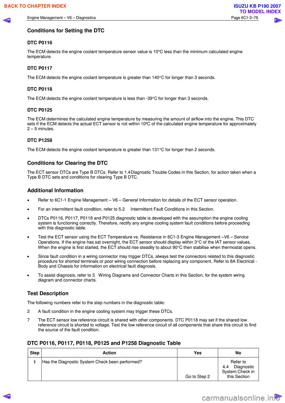
Conditions for Setting the DTC
DTC P0116
The ECM detects the engine coolant temperature sensor value is 10°C less than the minimum calculated engine
temperature.
DTC P0117
The ECM detects the engine coolant temperature is greater than 140 °C for longer than 3 seconds.
DTC P0118
The ECM detects the engine coolant temperature is less than -39 °C for longer than 3 seconds.
DTC P0125
The ECM determines the calculated engine temperature by measuring the amount of airflow into the engine. This DTC
sets if the ECM detects the actual ECT sensor is not within 10ºC of the calculated engine temperature for approximately
2 – 5 minutes.
DTC P1258
The ECM detects the engine coolant temperature is greater than 131 °C for longer than 2 seconds.
Conditions for Clearing the DTC
The ECT sensor DTCs are Type B DTCs. Refer to 1.4 Diagnostic Trouble Codes in this Section, for action taken when a
Type B DTC sets and conditions for clearing Type B DTC.
Additional Information
• Refer to 6C1-1 Engine Management – V6 – General Information for details of the ECT sensor operation.
• For an intermittent fault condition, refer to 5.2 Intermittent Fault Conditions in this Section.
• DTCs P0116, P0117, P0118 and P0125 diagnostic table is developed with the assumption the engine cooling
system is functioning correctly. Therefore, rectify any engine cooling system fault conditions before proceeding
with this diagnostic table.
• Test the ECT sensor using the ECT Temperature vs. Resistance in 6C1-3 Engine Management –V6 – Service
Operations. If the engine has sat overnight, the ECT sensor should display within 3 °C of the IAT sensor values.
W hen the engine is first started, the ECT should rise steadily to about 90 °C then stabilise when thermostat opens.
• Since fault condition in a wiring connector may trigger DTCs, always test the connectors related to this diagnostic
procedure for shorted terminals or poor wiring connection before replacing any component. Refer to 8A Electrical -
Body and Chassis for information on electrical fault diagnosis.
• To assist diagnosis, refer to 3 W iring Diagrams and Connector Charts in this Section, for the system wiring
diagram and connector charts.
Test Description
The following numbers refer to the step numbers in the diagnostic table:
2 A fault condition in the engine cooling system may trigger these DTCs.
7 The ECT sensor low reference circuit is shared with other components. DTC P0118 may set if the shared low reference circuit is shorted to voltage. Test the low reference circuit of all components that share this circuit to find
the source of the fault condition.
DTC P0116, P0117, P0118, P0125 and P1258 Diagnostic Table
Step Action Yes No
1 Has the Diagnostic System Check been performed?
Go to Step 2 Refer to
4.4 Diagnostic
System Check in this Section
BACK TO CHAPTER INDEX
TO MODEL INDEX
ISUZU KB P190 2007
Page 3356 of 6020
Engine Management – V6 – Diagnostics Page 6C1-2–78
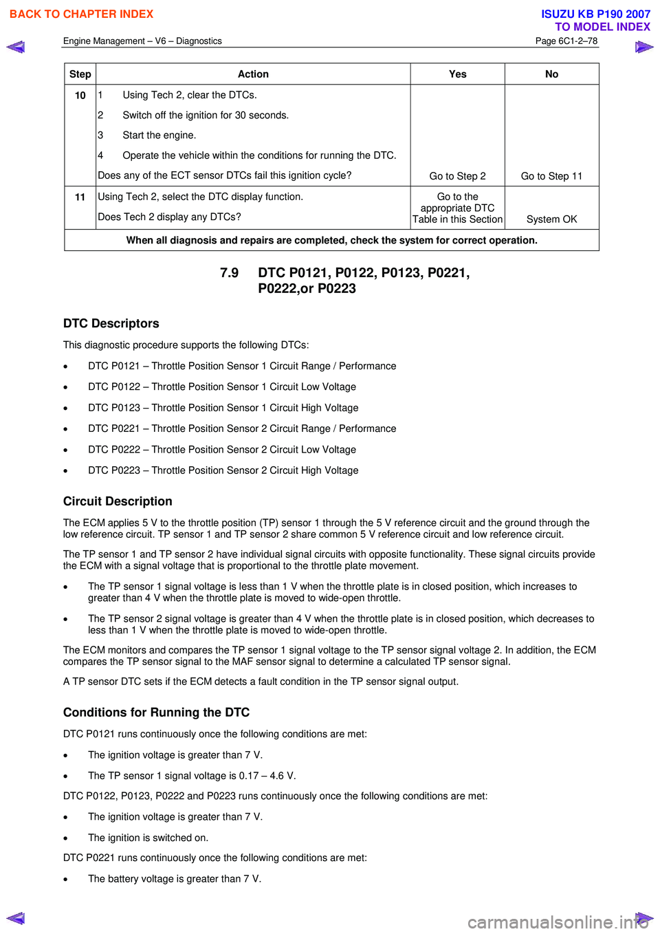
Step Action Yes No
10 1 Using Tech 2, clear the DTCs.
2 Switch off the ignition for 30 seconds.
3 Start the engine.
4 Operate the vehicle within the conditions for running the DTC.
Does any of the ECT sensor DTCs fail this ignition cycle? Go to Step 2 Go to Step 11
11 Using Tech 2, select the DTC display function.
Does Tech 2 display any DTCs? Go to the
appropriate DTC
Table in this Section System OK
When all diagnosis and repairs are completed, check the system for correct operation.
7.9 DTC P0121, P0122, P0123, P0221,
P0222,or P0223
DTC Descriptors
This diagnostic procedure supports the following DTCs:
• DTC P0121 – Throttle Position Sensor 1 Circuit Range / Performance
• DTC P0122 – Throttle Position Sensor 1 Circuit Low Voltage
• DTC P0123 – Throttle Position Sensor 1 Circuit High Voltage
• DTC P0221 – Throttle Position Sensor 2 Circuit Range / Performance
• DTC P0222 – Throttle Position Sensor 2 Circuit Low Voltage
• DTC P0223 – Throttle Position Sensor 2 Circuit High Voltage
Circuit Description
The ECM applies 5 V to the throttle position (TP) sensor 1 through the 5 V reference circuit and the ground through the
low reference circuit. TP sensor 1 and TP sensor 2 share common 5 V reference circuit and low reference circuit.
The TP sensor 1 and TP sensor 2 have individual signal circuits with opposite functionality. These signal circuits provide
the ECM with a signal voltage that is proportional to the throttle plate movement.
• The TP sensor 1 signal voltage is less than 1 V when the throttle plate is in closed position, which increases to
greater than 4 V when the throttle plate is moved to wide-open throttle.
• The TP sensor 2 signal voltage is greater than 4 V when the throttle plate is in closed position, which decreases to
less than 1 V when the throttle plate is moved to wide-open throttle.
The ECM monitors and compares the TP sensor 1 signal voltage to the TP sensor signal voltage 2. In addition, the ECM
compares the TP sensor signal to the MAF sensor signal to determine a calculated TP sensor signal.
A TP sensor DTC sets if the ECM detects a fault condition in the TP sensor signal output.
Conditions for Running the DTC
DTC P0121 runs continuously once the following conditions are met:
• The ignition voltage is greater than 7 V.
• The TP sensor 1 signal voltage is 0.17 – 4.6 V.
DTC P0122, P0123, P0222 and P0223 runs continuously once the following conditions are met:
• The ignition voltage is greater than 7 V.
• The ignition is switched on.
DTC P0221 runs continuously once the following conditions are met:
• The battery voltage is greater than 7 V.
BACK TO CHAPTER INDEX
TO MODEL INDEX
ISUZU KB P190 2007
Page 3358 of 6020
Engine Management – V6 – Diagnostics Page 6C1-2–80
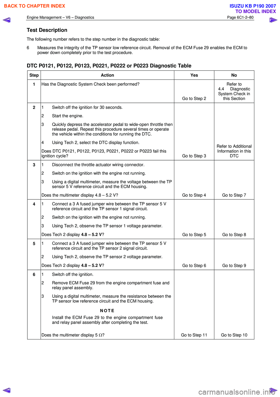
Test Description
The following number refers to the step number in the diagnostic table:
6 Measures the integrity of the TP sensor low reference circuit. Removal of the ECM Fuse 29 enables the ECM to power down completely prior to the test procedure.
DTC P0121, P0122, P0123, P0221, P0222 or P0223 Diagnostic Table
Step Action Yes No
1 Has the Diagnostic System Check been performed?
Go to Step 2 Refer to
4.4 Diagnostic
System Check in this Section
2 1 Switch off the ignition for 30 seconds.
2 Start the engine.
3 Quickly depress the accelerator pedal to wide-open throttle then release pedal. Repeat this procedure several times or operate
the vehicle within the conditions for running the DTC.
4 Using Tech 2, select the DTC display function.
Does DTC P0121, P0122, P0123, P0221, P0222 or P0223 fail this
ignition cycle? Go to Step 3 Refer to Additional
Information in this DTC
3 1 Disconnect the throttle actuator wiring connector.
2 Switch on the ignition with the engine not running.
3 Using a digital multimeter, measure the voltage between the TP sensor 5 V reference circuit and the ECM housing.
Does the multimeter display 4.8 – 5.2 V? Go to Step 4 Go to Step 7
4 1 Connect a 3 A fused jumper wire between the TP sensor 5 V
reference circuit and the TP sensor 1 signal circuit.
2 Switch on the ignition with the engine not running.
3 Using Tech 2, observe the TP sensor 1 voltage parameter.
Does Tech 2 display 4.8 – 5.2 V?
Go to Step 5 Go to Step 8
5 1 Connect a 3 A fused jumper wire between the TP sensor 5 V
reference circuit and the TP sensor 2 signal circuit.
2 Using Tech 2, observe the TP sensor 2 voltage parameter.
Does Tech 2 display 4.8 – 5.2 V?
Go to Step 6 Go to Step 9
6 1 Switch off the ignition.
2 Remove ECM Fuse 29 from the engine compartment fuse and relay panel assembly.
3 Using a digital multimeter, measure the resistance between the TP sensor low reference circuit and the ECM housing.
NOTE
Install the ECM Fuse 29 to the engine compartment fuse
and relay panel assembly after completing the test.
Does the multimeter display 5 Ω? Go to Step 11 Go to Step 10
BACK TO CHAPTER INDEX
TO MODEL INDEX
ISUZU KB P190 2007
Page 3359 of 6020
Engine Management – V6 – Diagnostics Page 6C1-2–81
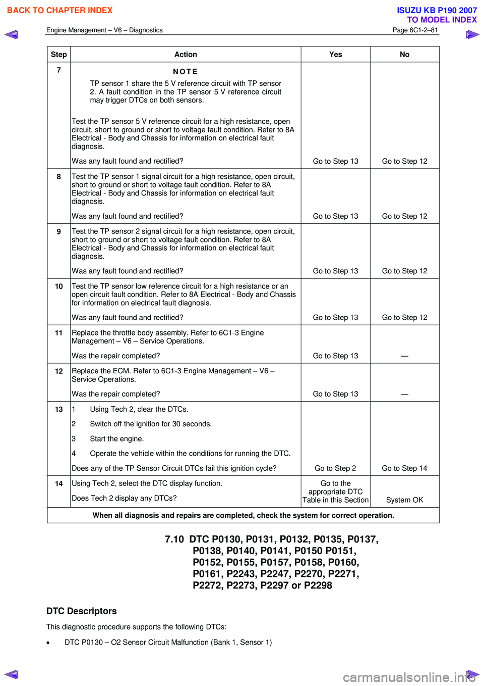
Step Action Yes No
7
NOTE
TP sensor 1 share the 5 V reference circuit with TP sensor
2. A fault condition in the TP sensor 5 V reference circuit
may trigger DTCs on both sensors.
Test the TP sensor 5 V reference circuit for a high resistance, open
circuit, short to ground or short to voltage fault condition. Refer to 8A
Electrical - Body and Chassis for information on electrical fault
diagnosis.
W as any fault found and rectified? Go to Step 13 Go to Step 12
8 Test the TP sensor 1 signal circuit for a high resistance, open circuit,
short to ground or short to voltage fault condition. Refer to 8A
Electrical - Body and Chassis for information on electrical fault
diagnosis.
W as any fault found and rectified? Go to Step 13 Go to Step 12
9 Test the TP sensor 2 signal circuit for a high resistance, open circuit,
short to ground or short to voltage fault condition. Refer to 8A
Electrical - Body and Chassis for information on electrical fault
diagnosis.
W as any fault found and rectified? Go to Step 13 Go to Step 12
10 Test the TP sensor low reference circuit for a high resistance or an
open circuit fault condition. Refer to 8A Electrical - Body and Chassis
for information on electrical fault diagnosis.
W as any fault found and rectified? Go to Step 13 Go to Step 12
11 Replace the throttle body assembly. Refer to 6C1-3 Engine
Management – V6 – Service Operations.
W as the repair completed? Go to Step 13 —
12 Replace the ECM. Refer to 6C1-3 Engine Management – V6 –
Service Operations.
W as the repair completed? Go to Step 13 —
13 1 Using Tech 2, clear the DTCs.
2 Switch off the ignition for 30 seconds.
3 Start the engine.
4 Operate the vehicle within the conditions for running the DTC.
Does any of the TP Sensor Circuit DTCs fail this ignition cycle? Go to Step 2 Go to Step 14
14 Using Tech 2, select the DTC display function.
Does Tech 2 display any DTCs? Go to the
appropriate DTC
Table in this Section System OK
When all diagnosis and repairs are completed, check the system for correct operation.
7.10 DTC P0130, P0131, P0132, P0135, P0137,
P0138, P0140, P0141, P0150 P0151,
P0152, P0155, P0157, P0158, P0160,
P0161, P2243, P2247, P2270, P2271,
P2272, P2273, P2297 or P2298
DTC Descriptors
This diagnostic procedure supports the following DTCs:
• DTC P0130 – O2 Sensor Circuit Malfunction (Bank 1, Sensor 1)
BACK TO CHAPTER INDEX
TO MODEL INDEX
ISUZU KB P190 2007
Page 3364 of 6020
Engine Management – V6 – Diagnostics Page 6C1-2–86
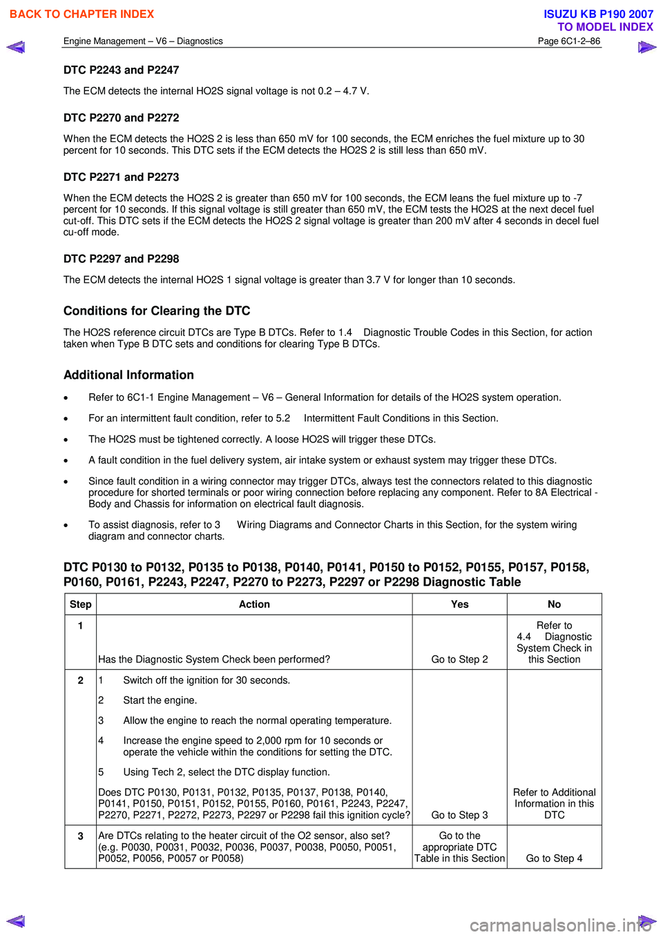
DTC P2243 and P2247
The ECM detects the internal HO2S signal voltage is not 0.2 – 4.7 V.
DTC P2270 and P2272
W hen the ECM detects the HO2S 2 is less than 650 mV for 100 seconds, the ECM enriches the fuel mixture up to 30
percent for 10 seconds. This DTC sets if the ECM detects the HO2S 2 is still less than 650 mV.
DTC P2271 and P2273
W hen the ECM detects the HO2S 2 is greater than 650 mV for 100 seconds, the ECM leans the fuel mixture up to -7
percent for 10 seconds. If this signal voltage is still greater than 650 mV, the ECM tests the HO2S at the next decel fuel
cut-off. This DTC sets if the ECM detects the HO2S 2 signal voltage is greater than 200 mV after 4 seconds in decel fuel
cu-off mode.
DTC P2297 and P2298
The ECM detects the internal HO2S 1 signal voltage is greater than 3.7 V for longer than 10 seconds.
Conditions for Clearing the DTC
The HO2S reference circuit DTCs are Type B DTCs. Refer to 1.4 Diagnostic Trouble Codes in this Section, for action
taken when Type B DTC sets and conditions for clearing Type B DTCs.
Additional Information
• Refer to 6C1-1 Engine Management – V6 – General Information for details of the HO2S system operation.
• For an intermittent fault condition, refer to 5.2 Intermittent Fault Conditions in this Section.
• The HO2S must be tightened correctly. A loose HO2S will trigger these DTCs.
• A fault condition in the fuel delivery system, air intake system or exhaust system may trigger these DTCs.
• Since fault condition in a wiring connector may trigger DTCs, always test the connectors related to this diagnostic
procedure for shorted terminals or poor wiring connection before replacing any component. Refer to 8A Electrical -
Body and Chassis for information on electrical fault diagnosis.
• To assist diagnosis, refer to 3 W iring Diagrams and Connector Charts in this Section, for the system wiring
diagram and connector charts.
DTC P0130 to P0132, P0135 to P0138, P0140, P0141, P0150 to P0152, P0155, P0157, P0158,
P0160, P0161, P2243, P2247, P2270 to P2273, P2297 or P2298 Diagnostic Table
Step Action Yes No
1
Has the Diagnostic System Check been performed? Go to Step 2 Refer to
4.4 Diagnostic
System Check in this Section
2 1 Switch off the ignition for 30 seconds.
2 Start the engine.
3 Allow the engine to reach the normal operating temperature.
4 Increase the engine speed to 2,000 rpm for 10 seconds or operate the vehicle within the conditions for setting the DTC.
5 Using Tech 2, select the DTC display function.
Does DTC P0130, P0131, P0132, P0135, P0137, P0138, P0140,
P0141, P0150, P0151, P0152, P0155, P0160, P0161, P2243, P2247,
P2270, P2271, P2272, P2273, P2297 or P2298 fail this ignition cycle? Go to Step 3 Refer to Additional
Information in this DTC
3 Are DTCs relating to the heater circuit of the O2 sensor, also set?
(e.g. P0030, P0031, P0032, P0036, P0037, P0038, P0050, P0051,
P0052, P0056, P0057 or P0058) Go to the
appropriate DTC
Table in this Section Go to Step 4
BACK TO CHAPTER INDEX
TO MODEL INDEX
ISUZU KB P190 2007
Page 3365 of 6020
Engine Management – V6 – Diagnostics Page 6C1-2–87
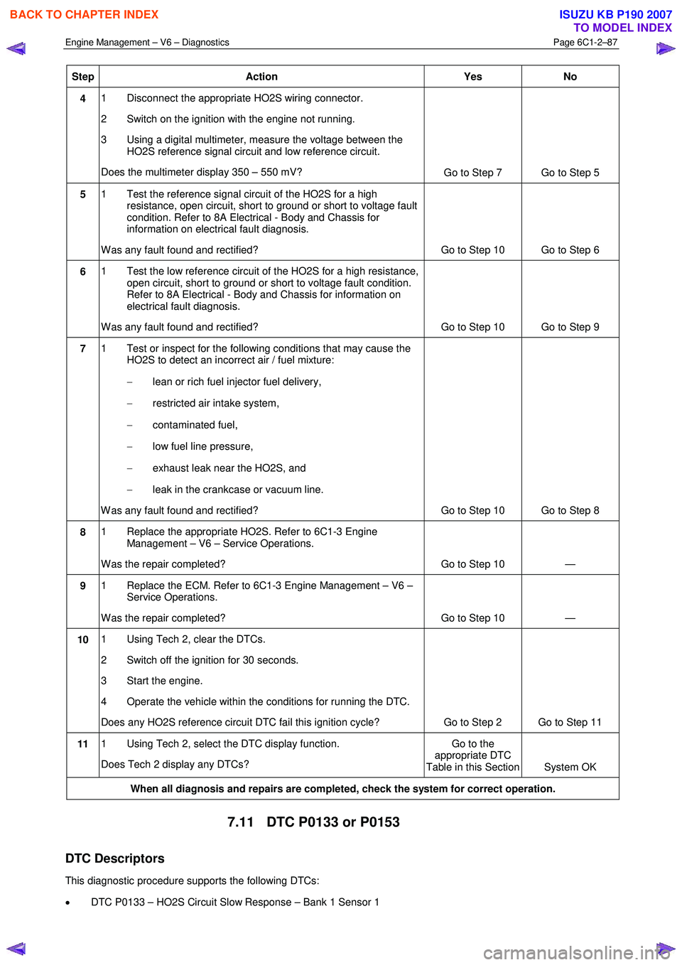
Step Action Yes No
4 1 Disconnect the appropriate HO2S wiring connector.
2 Switch on the ignition with the engine not running.
3 Using a digital multimeter, measure the voltage between the HO2S reference signal circuit and low reference circuit.
Does the multimeter display 350 – 550 mV? Go to Step 7 Go to Step 5
5 1 Test the reference signal circuit of the HO2S for a high
resistance, open circuit, short to ground or short to voltage fault
condition. Refer to 8A Electrical - Body and Chassis for
information on electrical fault diagnosis.
W as any fault found and rectified? Go to Step 10 Go to Step 6
6 1 Test the low reference circuit of the HO2S for a high resistance,
open circuit, short to ground or short to voltage fault condition.
Refer to 8A Electrical - Body and Chassis for information on
electrical fault diagnosis.
W as any fault found and rectified? Go to Step 10 Go to Step 9
7 1 Test or inspect for the following conditions that may cause the
HO2S to detect an incorrect air / fuel mixture:
− lean or rich fuel injector fuel delivery,
− restricted air intake system,
− contaminated fuel,
− low fuel line pressure,
− exhaust leak near the HO2S, and
− leak in the crankcase or vacuum line.
W as any fault found and rectified? Go to Step 10 Go to Step 8
8 1 Replace the appropriate HO2S. Refer to 6C1-3 Engine
Management – V6 – Service Operations.
W as the repair completed? Go to Step 10 —
9 1 Replace the ECM. Refer to 6C1-3 Engine Management – V6 –
Service Operations.
W as the repair completed? Go to Step 10 —
10 1 Using Tech 2, clear the DTCs.
2 Switch off the ignition for 30 seconds.
3 Start the engine.
4 Operate the vehicle within the conditions for running the DTC.
Does any HO2S reference circuit DTC fail this ignition cycle? Go to Step 2 Go to Step 11
11 1 Using Tech 2, select the DTC display function.
Does Tech 2 display any DTCs? Go to the
appropriate DTC
Table in this Section System OK
When all diagnosis and repairs are completed, check the system for correct operation.
7.11 DTC P0133 or P0153
DTC Descriptors
This diagnostic procedure supports the following DTCs:
• DTC P0133 – HO2S Circuit Slow Response – Bank 1 Sensor 1
BACK TO CHAPTER INDEX
TO MODEL INDEX
ISUZU KB P190 2007