2007 INFINITI QX56 engine coolant
[x] Cancel search: engine coolantPage 1300 of 3061
DTC P0125 ECT SENSOR
EC-217
< SERVICE INFORMATION >
C
D
E
F
G
H
I
J
K
L
MA
EC
N
P O
DTC P0125 ECT SENSOR
Component DescriptionINFOID:0000000003531719
NOTE:
If DTC P0125 is displayed with P0117 or P0118, first perform the trouble diagnosis for DTC P0117 or
P0118. Refer to EC-205
.
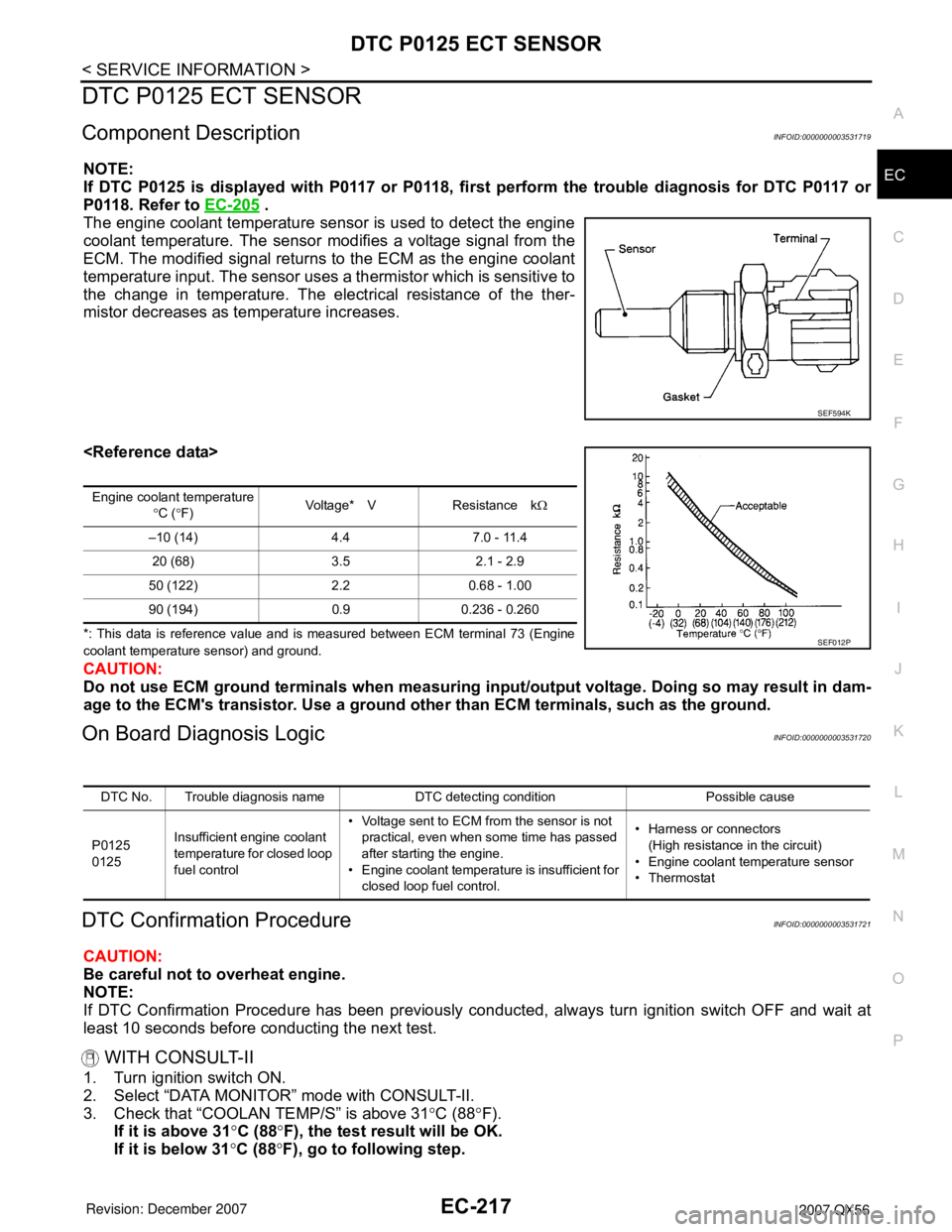
The engine coolant temperature sensor is used to detect the engine
coolant temperature. The sensor modifies a voltage signal from the
ECM. The modified signal returns to the ECM as the engine coolant
temperature input. The sensor uses a thermistor which is sensitive to
the change in temperature. The electrical resistance of the ther-
mistor decreases as temperature increases.
*: This data is reference value and is measured between ECM terminal 73 (Engine
coolant temperature sensor) and ground.
CAUTION:
Do not use ECM ground terminals when measuring input/output voltage. Doing so may result in dam-
age to the ECM's transistor. Use a ground other than ECM terminals, such as the ground.
On Board Diagnosis LogicINFOID:0000000003531720
DTC Confirmation ProcedureINFOID:0000000003531721
CAUTION:
Be careful not to overheat engine.
NOTE:
If DTC Confirmation Procedure has been previously conducted, always turn ignition switch OFF and wait at
least 10 seconds before conducting the next test.
WITH CONSULT-II
1. Turn ignition switch ON.
2. Select “DATA MONITOR” mode with CONSULT-II.
3. Check that “COOLAN TEMP/S” is above 31°C (88°F).
If it is above 31°C (88°F), the test result will be OK.
If it is below 31°C (88°F), go to following step.
SEF594K
Engine coolant temperature
°C (°F)Voltage* V Resistance kΩ
–10 (14) 4.4 7.0 - 11.4
20 (68) 3.5 2.1 - 2.9
50 (122) 2.2 0.68 - 1.00
90 (194) 0.9 0.236 - 0.260
SEF012P
DTC No. Trouble diagnosis name DTC detecting condition Possible cause
P0125
0125Insufficient engine coolant
temperature for closed loop
fuel control• Voltage sent to ECM from the sensor is not
practical, even when some time has passed
after starting the engine.
• Engine coolant temperature is insufficient for
closed loop fuel control.• Harness or connectors
(High resistance in the circuit)
• Engine coolant temperature sensor
•Thermostat
Page 1301 of 3061
EC-218
< SERVICE INFORMATION >
DTC P0125 ECT SENSOR
4. Start engine and run it for 65 minutes at idle speed.
If “COOLAN TEMP/S” increases to more than 31°C (88°F)
within 65 minutes, stop engine because the test result will
be OK.
5. If 1st trip DTC is detected, go to EC-218, "
Diagnosis Procedure"
.
WITH GST
Follow the procedure “WITH CONSULT-II” above.
Diagnosis ProcedureINFOID:0000000003531722
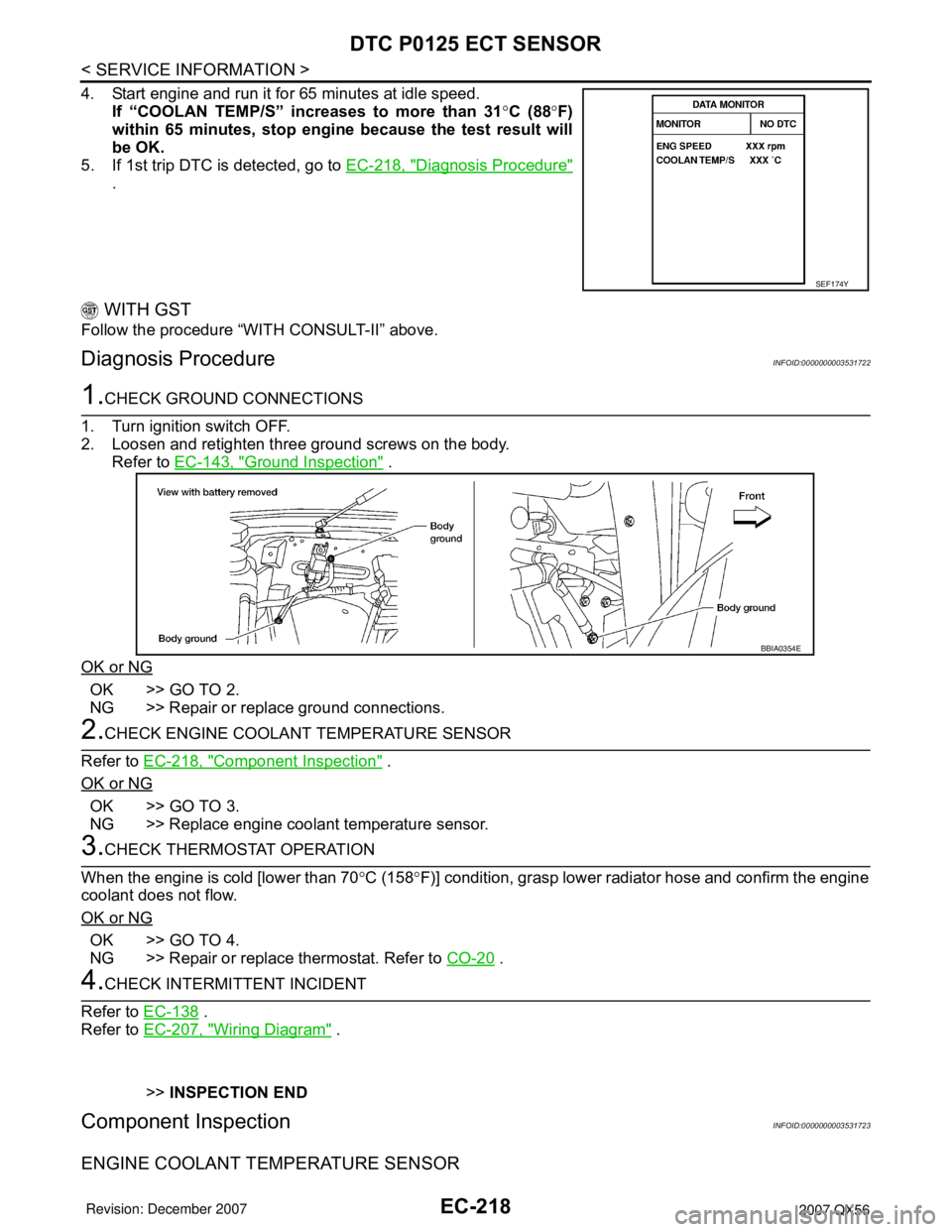
1.CHECK GROUND CONNECTIONS
1. Turn ignition switch OFF.
2. Loosen and retighten three ground screws on the body.
Refer to EC-143, "
Ground Inspection" .
OK or NG
OK >> GO TO 2.
NG >> Repair or replace ground connections.
2.CHECK ENGINE COOLANT TEMPERATURE SENSOR
Refer to EC-218, "
Component Inspection" .
OK or NG
OK >> GO TO 3.
NG >> Replace engine coolant temperature sensor.
3.CHECK THERMOSTAT OPERATION
When the engine is cold [lower than 70°C (158°F)] condition, grasp lower radiator hose and confirm the engine
coolant does not flow.
OK or NG
OK >> GO TO 4.
NG >> Repair or replace thermostat. Refer to CO-20
.
4.CHECK INTERMITTENT INCIDENT
Refer to EC-138
.
Refer to EC-207, "
Wiring Diagram" .
>>INSPECTION END
Component InspectionINFOID:0000000003531723
ENGINE COOLANT TEMPERATURE SENSOR
SEF174Y
BBIA0354E
Page 1302 of 3061
DTC P0125 ECT SENSOR
EC-219
< SERVICE INFORMATION >
C
D
E
F
G
H
I
J
K
L
MA
EC
N
P O
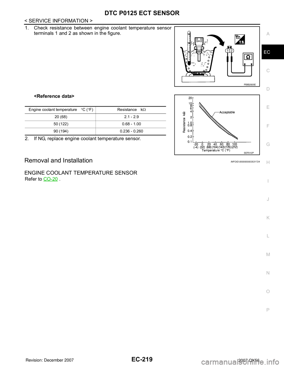
1. Check resistance between engine coolant temperature sensor
terminals 1 and 2 as shown in the figure.
2. If NG, replace engine coolant temperature sensor.
Removal and InstallationINFOID:0000000003531724
ENGINE COOLANT TEMPERATURE SENSOR
Refer to CO-20 .
PBIB2005E
Engine coolant temperature°C (°F) Resistance kΩ
20 (68) 2.1 - 2.9
50 (122) 0.68 - 1.00
90 (194) 0.236 - 0.260
SEF012P
Page 1303 of 3061
EC-220
< SERVICE INFORMATION >
DTC P0127 IAT SENSOR
DTC P0127 IAT SENSOR
Component DescriptionINFOID:0000000003531725
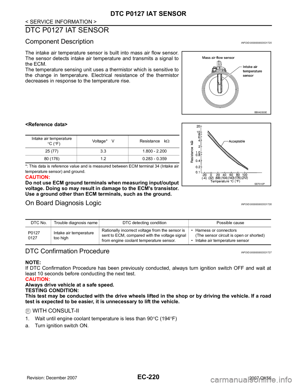
The intake air temperature sensor is built into mass air flow sensor.
The sensor detects intake air temperature and transmits a signal to
the ECM.
The temperature sensing unit uses a thermistor which is sensitive to
the change in temperature. Electrical resistance of the thermistor
decreases in response to the temperature rise.
*: This data is reference value and is measured between ECM terminal 34 (Intake air
temperature sensor) and ground.
CAUTION:
Do not use ECM ground terminals when measuring input/output
voltage. Doing so may result in damage to the ECM's transistor.
Use a ground other than ECM terminals, such as the ground.
On Board Diagnosis LogicINFOID:0000000003531726
DTC Confirmation ProcedureINFOID:0000000003531727
NOTE:
If DTC Confirmation Procedure has been previously conducted, always turn ignition switch OFF and wait at
least 10 seconds before conducting the next test.
CAUTION:
Always drive vehicle at a safe speed.
TESTING CONDITION:
This test may be conducted with the drive wheels lifted in the shop or by driving the vehicle. If a road
test is expected to be easier, it is unnecessary to lift the vehicle.
WITH CONSULT-II
1. Wait until engine coolant temperature is less than 90°C (194°F)
a. Turn ignition switch ON.
BBIA0355E
Intake air temperature
°C (°F)Voltage* V Resistance kΩ
25 (77) 3.3 1.800 - 2.200
80 (176) 1.2 0.283 - 0.359
SEF012P
DTC No. Trouble diagnosis name DTC detecting condition Possible cause
P0127
0127Intake air temperature
too highRationally incorrect voltage from the sensor is
sent to ECM, compared with the voltage signal
from engine coolant temperature sensor.• Harness or connectors
(The sensor circuit is open or shorted)
• Intake air temperature sensor
Page 1304 of 3061
DTC P0127 IAT SENSOR
EC-221
< SERVICE INFORMATION >
C
D
E
F
G
H
I
J
K
L
MA
EC
N
P O
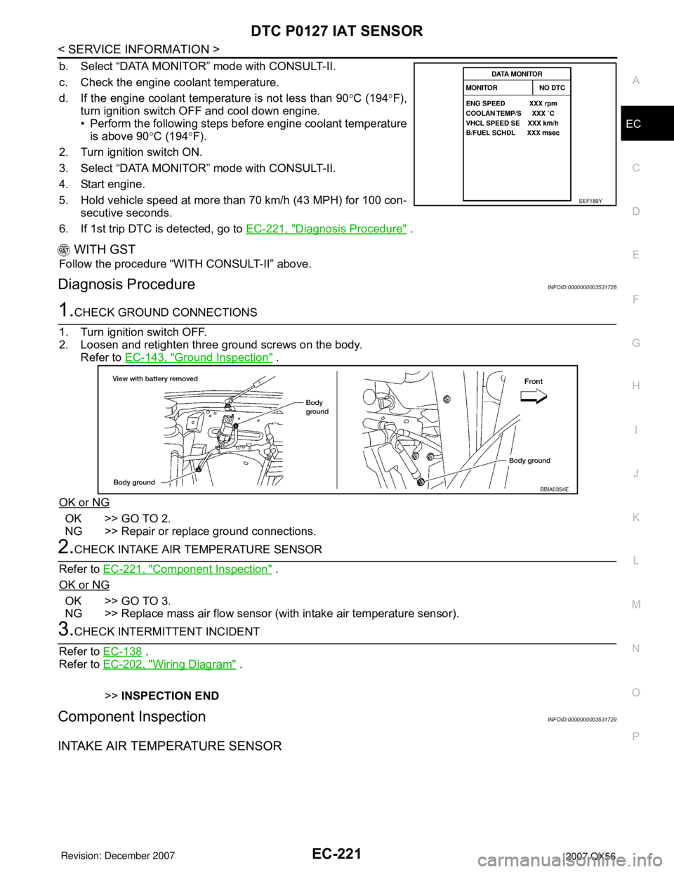
b. Select “DATA MONITOR” mode with CONSULT-II.
c. Check the engine coolant temperature.
d. If the engine coolant temperature is not less than 90°C (194°F),
turn ignition switch OFF and cool down engine.
• Perform the following steps before engine coolant temperature
is above 90°C (194°F).
2. Turn ignition switch ON.
3. Select “DATA MONITOR” mode with CONSULT-II.
4. Start engine.
5. Hold vehicle speed at more than 70 km/h (43 MPH) for 100 con-
secutive seconds.
6. If 1st trip DTC is detected, go to EC-221, "
Diagnosis Procedure" .
WITH GST
Follow the procedure “WITH CONSULT-II” above.
Diagnosis ProcedureINFOID:0000000003531728
1.CHECK GROUND CONNECTIONS
1. Turn ignition switch OFF.
2. Loosen and retighten three ground screws on the body.
Refer to EC-143, "
Ground Inspection" .
OK or NG
OK >> GO TO 2.
NG >> Repair or replace ground connections.
2.CHECK INTAKE AIR TEMPERATURE SENSOR
Refer to EC-221, "
Component Inspection" .
OK or NG
OK >> GO TO 3.
NG >> Replace mass air flow sensor (with intake air temperature sensor).
3.CHECK INTERMITTENT INCIDENT
Refer to EC-138
.
Refer to EC-202, "
Wiring Diagram" .
>>INSPECTION END
Component InspectionINFOID:0000000003531729
INTAKE AIR TEMPERATURE SENSOR
SEF189Y
BBIA0354E
Page 1306 of 3061

DTC P0128 THERMOSTAT FUNCTION
EC-223
< SERVICE INFORMATION >
C
D
E
F
G
H
I
J
K
L
MA
EC
N
P O
DTC P0128 THERMOSTAT FUNCTION
On Board Diagnosis LogicINFOID:0000000003531731
Engine coolant temperature has not risen enough to open the thermostat even though the engine has run long
enough.
This is due to a leak in the seal or the thermostat stuck open.
DTC Confirmation ProcedureINFOID:0000000003531732
NOTE:
If DTC Confirmation Procedure has been previously conducted, always turn ignition switch OFF and wait at
least 10 seconds before conducting the next test.
TESTING CONDITION:
•For best results, perform at ambient temperature of –10°C (14°F) or higher.
•For best results, perform at engine coolant temperature of –10°C (14°F) to 72°C (162°F).
WITH CONSULT-II
1. Replace thermostat with new one. Refer to CO-20 . Use only a genuine NISSAN thermostat as a replace-
ment. If an incorrect thermostat is used, the MIL may come on.
2. Turn ignition switch ON.
3. Select “COOLAN TEMP/S” in “DATA MONITOR” mode with CONSULT-II.
4. Check that the “COOLAN TEMP/S” is above 72°C (162°F).
If it is below 72°C (162°F), go to following step.
If it is above 72°C (162°F), cool down the engine to less than 72°C (162°F), then retry from step 1.
5. Drive vehicle for 10 consecutive minutes under the following conditions.
If 1st trip DTC is detected, go to EC-223, "
Diagnosis Procedure" .
WITH GST
1. Follow the procedure “WITH CONSULT-II” above.
Diagnosis ProcedureINFOID:0000000003531733
1.CHECK ENGINE COOLANT TEMPERATURE SENSOR
Refer to EC-223, "
Component Inspection" .
OK or NG
OK >>INSPECTION END
NG >> Replace engine coolant temperature sensor.
Component InspectionINFOID:0000000003531734
ENGINE COOLANT TEMPERATURE SENSOR
DTC No. Trouble diagnosis name DTC detecting condition Possible cause
P0128
0128Thermostat functionThe engine coolant temperature does not
reach to specified temperature even though
the engine has run long enough.•Thermostat
• Leakage from sealing portion of thermostat
• Engine coolant temperature sensor
VHCL SPEED SE 80 - 120 km/h (50 - 75 MPH)
Page 1307 of 3061
EC-224
< SERVICE INFORMATION >
DTC P0128 THERMOSTAT FUNCTION
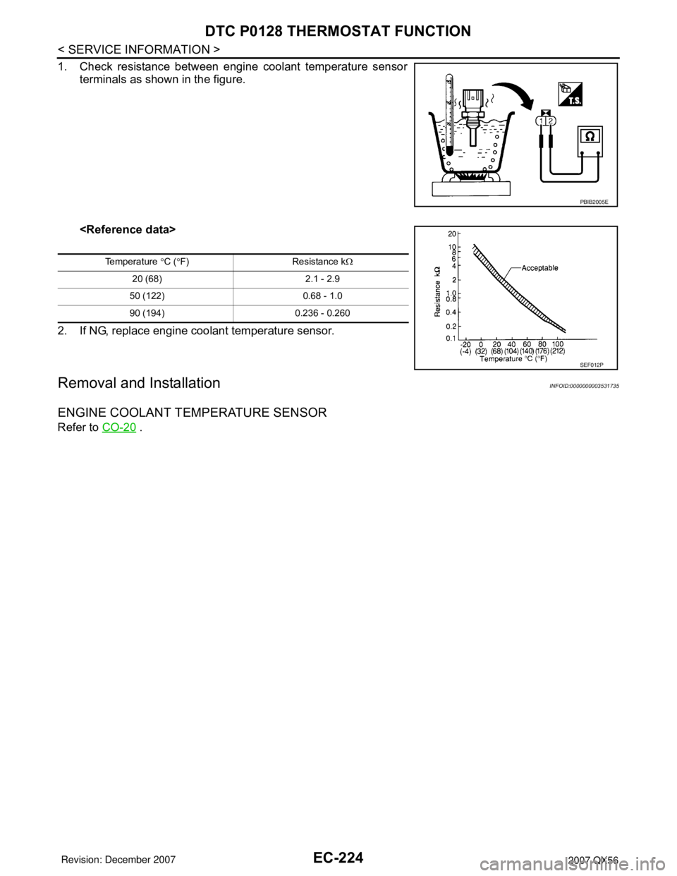
1. Check resistance between engine coolant temperature sensor
terminals as shown in the figure.
2. If NG, replace engine coolant temperature sensor.
Removal and InstallationINFOID:0000000003531735
ENGINE COOLANT TEMPERATURE SENSOR
Refer to CO-20 .
PBIB2005E
Temperature °C (°F) Resistance kΩ
20 (68) 2.1 - 2.9
50 (122) 0.68 - 1.0
90 (194) 0.236 - 0.260
SEF012P
Page 1376 of 3061
DTC P0171, P0174 FUEL INJECTION SYSTEM FUNCTION
EC-293
< SERVICE INFORMATION >
C
D
E
F
G
H
I
J
K
L
MA
EC
N
P O7. If it is difficult to start engine at step 6, the fuel injection system has a malfunction, too.
8. Crank engine while depressing accelerator pedal. If engine starts, go to EC-297, "
Diagnosis Procedure". If
engine does not start, check exhaust and intake air leak visually.
WITH GST
1. Start engine and warm it up to normal operating temperature.
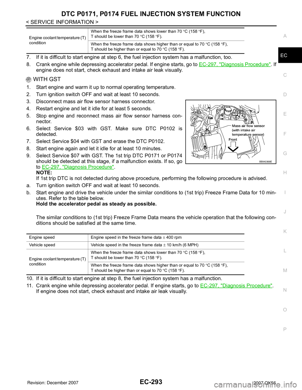
2. Turn ignition switch OFF and wait at least 10 seconds.
3. Disconnect mass air flow sensor harness connector.
4. Restart engine and let it idle for at least 5 seconds.
5. Stop engine and reconnect mass air flow sensor harness con-
nector.
6. Select Service $03 with GST. Make sure DTC P0102 is
detected.
7. Select Service $04 with GST and erase the DTC P0102.
8. Start engine again and let it idle for at least 10 minutes.
9. Select Service $07 with GST. The 1st trip DTC P0171 or P0174
should be detected at this stage, if a malfunction exists. If so, go
to EC-297, "
Diagnosis Procedure".
NOTE:
If 1st trip DTC is not detected during above procedure, performing the following procedure is advised.
a. Turn ignition switch OFF and wait at least 10 seconds.
b. Start engine and drive the vehicle under the similar conditions to (1st trip) Freeze Frame Data for 10 min-
utes. Refer to the table below.
Hold the accelerator pedal as steady as possible.
The similar conditions to (1st trip) Freeze Frame Data means the vehicle operation that the following con-
ditions should be satisfied at the same time.
10. If it is difficult to start engine at step 8, the fuel injection system has a malfunction.
11. Crank engine while depressing accelerator pedal. If engine starts, go to EC-297, "
Diagnosis Procedure".
If engine does not start, check exhaust and intake air leak visually.
Engine coolant temperature (T)
conditionWhen the freeze frame data shows lower than 70 °C (158 °F),
T should be lower than 70 °C (158 °F).
When the freeze frame data shows higher than or equal to 70 °C (158 °F),
T should be higher than or equal to 70 °C (158 °F).
BBIA0368E
Engine speed Engine speed in the freeze frame data ± 400 rpm
Vehicle speed Vehicle speed in the freeze frame data ± 10 km/h (6 MPH)
Engine coolant temperature (T)
conditionWhen the freeze frame data shows lower than 70 °C (158 °F),
T should be lower than 70 °C (158 °F).
When the freeze frame data shows higher than or equal to 70 °C (158 °F),
T should be higher than or equal to 70 °C (158 °F).