2007 INFINITI QX56 air condition
[x] Cancel search: air conditionPage 2935 of 3061
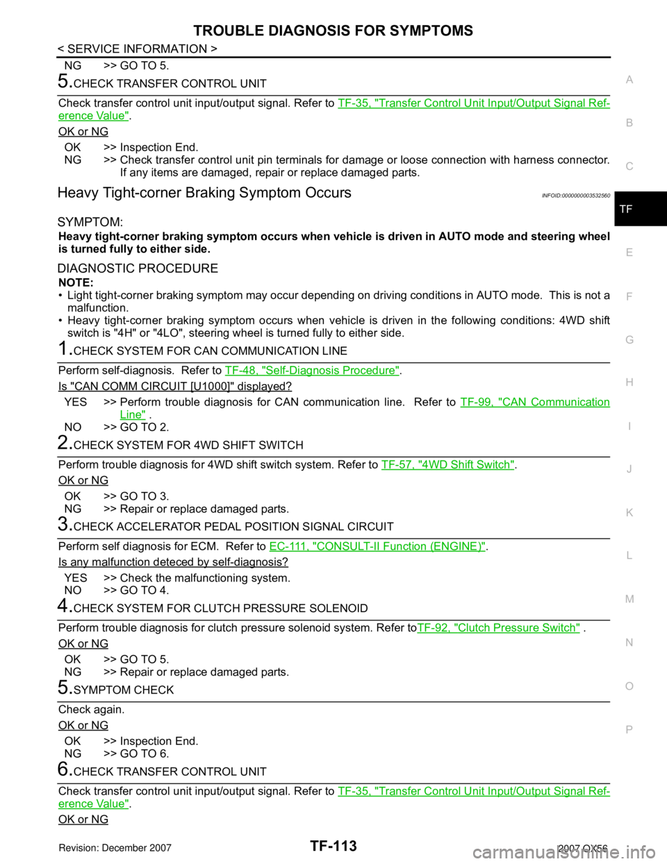
TROUBLE DIAGNOSIS FOR SYMPTOMS
TF-113
< SERVICE INFORMATION >
C
E
F
G
H
I
J
K
L
MA
B
TF
N
O
P
NG >> GO TO 5.
5.CHECK TRANSFER CONTROL UNIT
Check transfer control unit input/output signal. Refer to TF-35, "
Transfer Control Unit Input/Output Signal Ref-
erence Value".
OK or NG
OK >> Inspection End.
NG >> Check transfer control unit pin terminals for damage or loose connection with harness connector.
If any items are damaged, repair or replace damaged parts.
Heavy Tight-corner Braking Symptom OccursINFOID:0000000003532560
SYMPTOM:
Heavy tight-corner braking symptom occurs when vehicle is driven in AUTO mode and steering wheel
is turned fully to either side.
DIAGNOSTIC PROCEDURE
NOTE:
• Light tight-corner braking symptom may occur depending on driving conditions in AUTO mode. This is not a
malfunction.
• Heavy tight-corner braking symptom occurs when vehicle is driven in the following conditions: 4WD shift
switch is "4H" or "4LO", steering wheel is turned fully to either side.
1.CHECK SYSTEM FOR CAN COMMUNICATION LINE
Perform self-diagnosis. Refer to TF-48, "
Self-Diagnosis Procedure".
Is "CAN COMM CIRCUIT [U1000]" displayed?
YES >> Perform trouble diagnosis for CAN communication line. Refer to TF-99, "CAN Communication
Line" .
NO >> GO TO 2.
2.CHECK SYSTEM FOR 4WD SHIFT SWITCH
Perform trouble diagnosis for 4WD shift switch system. Refer to TF-57, "
4WD Shift Switch".
OK or NG
OK >> GO TO 3.
NG >> Repair or replace damaged parts.
3.CHECK ACCELERATOR PEDAL POSITION SIGNAL CIRCUIT
Perform self diagnosis for ECM. Refer to E C - 111 , "
CONSULT-II Function (ENGINE)".
Is any malfunction deteced by self-diagnosis?
YES >> Check the malfunctioning system.
NO >> GO TO 4.
4.CHECK SYSTEM FOR CLUTCH PRESSURE SOLENOID
Perform trouble diagnosis for clutch pressure solenoid system. Refer toTF-92, "
Clutch Pressure Switch" .
OK or NG
OK >> GO TO 5.
NG >> Repair or replace damaged parts.
5.SYMPTOM CHECK
Check again.
OK or NG
OK >> Inspection End.
NG >> GO TO 6.
6.CHECK TRANSFER CONTROL UNIT
Check transfer control unit input/output signal. Refer to TF-35, "
Transfer Control Unit Input/Output Signal Ref-
erence Value".
OK or NG
Page 2997 of 3061

WT-8
< SERVICE INFORMATION >
LOW TIRE PRESSURE WARNING SYSTEM
LOW TIRE PRESSURE WARNING SYSTEM
System ComponentINFOID:0000000003532692
System DescriptionINFOID:0000000003532693
BODY CONTROL MODULE (BCM)
The BCM is shown with the lower instrument panel LH removed. The
BCM reads the air pressure signal received by the remote keyless
entry receiver, and controls the low tire pressure warning lamp as
shown below. It also has a self-diagnosis function to detect a system
malfunction.
TRANSMITTER
A sensor-transmitter integrated with a valve is installed in each
wheel, and transmits a detected air pressure signal in the form of a
radio wave. The radio signal is received by the remote keyless entry
receiver.
WEIA0081E
Condition Low tire pressure warning lamp
System normal On for 1 second after ignition ON
Tire less than 193 kPa (2.0 kg/cm
2 , 28 psi)
[Flat tire]ON
Low tire pressure warning system malfunc-
tionAfter key ON, flashes once per sec-
ond for 1 minute, then stays ON
LEIA0068E
WEIA0137E
Page 2998 of 3061
LOW TIRE PRESSURE WARNING SYSTEM
WT-9
< SERVICE INFORMATION >
C
D
F
G
H
I
J
K
L
MA
B
WT
N
O
P
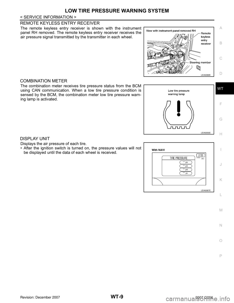
REMOTE KEYLESS ENTRY RECEIVER
The remote keyless entry receiver is shown with the instrument
panel RH removed. The remote keyless entry receiver receives the
air pressure signal transmitted by the transmitter in each wheel.
COMBINATION METER
The combination meter receives tire pressure status from the BCM
using CAN communication. When a low tire pressure condition is
sensed by the BCM, the combination meter low tire pressure warn-
ing lamp is activated.
DISPLAY UNIT
Displays the air pressure of each tire.
• After the ignition switch is turned on, the pressure values will not
be displayed until the data of each wheel is received.
LEIA0069E
LEIA0055E
LEIA0067E
Page 3005 of 3061
WT-16
< SERVICE INFORMATION >
TROUBLE DIAGNOSIS
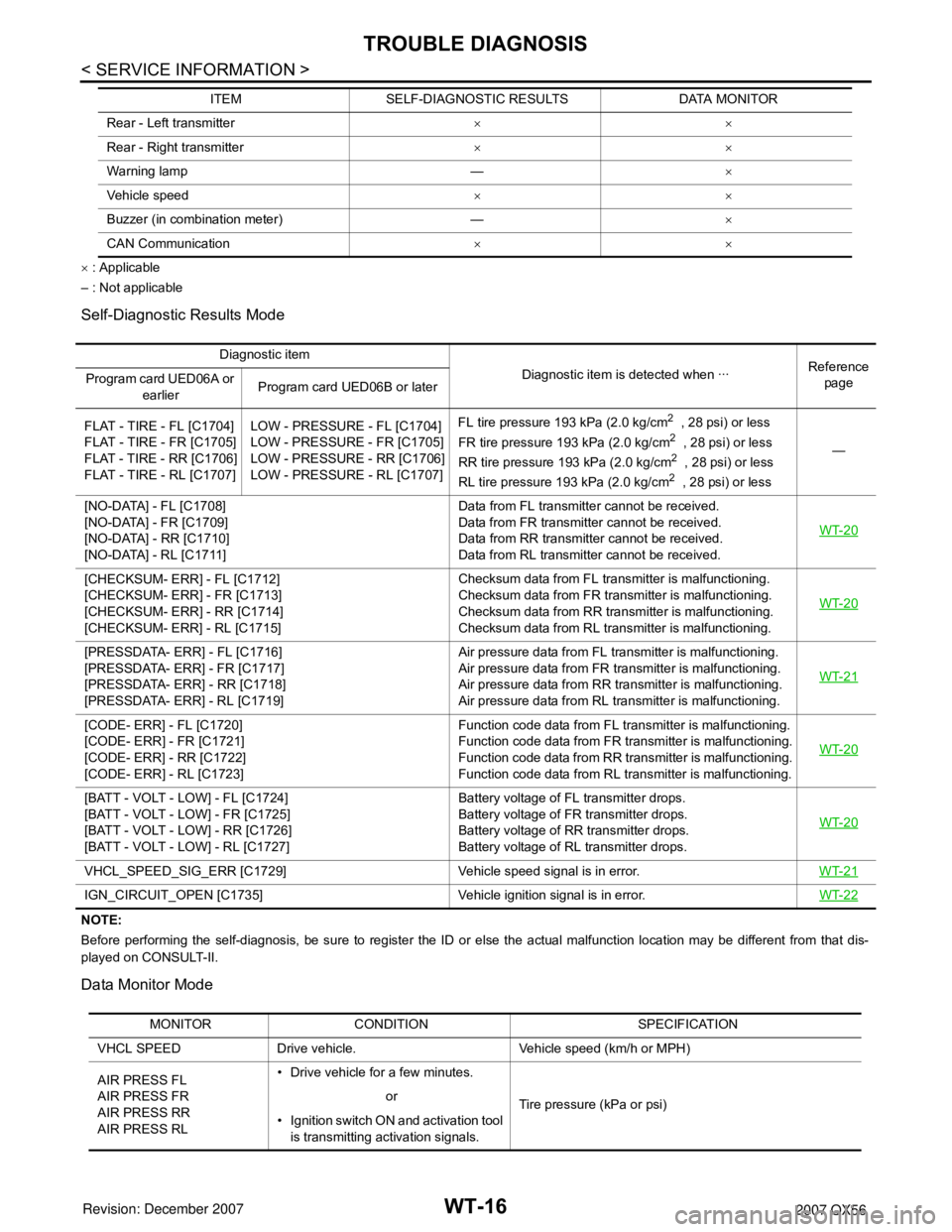
× : Applicable
– : Not applicable
Self-Diagnostic Results Mode
NOTE:
Before performing the self-diagnosis, be sure to register the ID or else the actual malfunction location may be different from that dis-
played on CONSULT-II.
Data Monitor Mode
Rear - Left transmitter××
Rear - Right transmitter××
Warning lamp —×
Vehicle speed××
Buzzer (in combination meter) —×
CAN Communication×× ITEM SELF-DIAGNOSTIC RESULTS DATA MONITOR
Diagnostic item
Diagnostic item is detected when ···Reference
page Program card UED06A or
earlierProgram card UED06B or later
FLAT - TIRE - FL [C1704]
FLAT - TIRE - FR [C1705]
FLAT - TIRE - RR [C1706]
FLAT - TIRE - RL [C1707]LOW - PRESSURE - FL [C1704]
LOW - PRESSURE - FR [C1705]
LOW - PRESSURE - RR [C1706]
LOW - PRESSURE - RL [C1707]FL tire pressure 193 kPa (2.0 kg/cm
2 , 28 psi) or less
FR tire pressure 193 kPa (2.0 kg/cm2 , 28 psi) or less
RR tire pressure 193 kPa (2.0 kg/cm2 , 28 psi) or less
RL tire pressure 193 kPa (2.0 kg/cm2 , 28 psi) or less—
[NO-DATA] - FL [C1708]
[NO-DATA] - FR [C1709]
[NO-DATA] - RR [C1710]
[NO-DATA] - RL [C1711]Data from FL transmitter cannot be received.
Data from FR transmitter cannot be received.
Data from RR transmitter cannot be received.
Data from RL transmitter cannot be received.WT-20
[CHECKSUM- ERR] - FL [C1712]
[CHECKSUM- ERR] - FR [C1713]
[CHECKSUM- ERR] - RR [C1714]
[CHECKSUM- ERR] - RL [C1715]Checksum data from FL transmitter is malfunctioning.
Checksum data from FR transmitter is malfunctioning.
Checksum data from RR transmitter is malfunctioning.
Checksum data from RL transmitter is malfunctioning.WT-20
[PRESSDATA- ERR] - FL [C1716]
[PRESSDATA- ERR] - FR [C1717]
[PRESSDATA- ERR] - RR [C1718]
[PRESSDATA- ERR] - RL [C1719]Air pressure data from FL transmitter is malfunctioning.
Air pressure data from FR transmitter is malfunctioning.
Air pressure data from RR transmitter is malfunctioning.
Air pressure data from RL transmitter is malfunctioning.WT-21
[CODE- ERR] - FL [C1720]
[CODE- ERR] - FR [C1721]
[CODE- ERR] - RR [C1722]
[CODE- ERR] - RL [C1723]Function code data from FL transmitter is malfunctioning.
Function code data from FR transmitter is malfunctioning.
Function code data from RR transmitter is malfunctioning.
Function code data from RL transmitter is malfunctioning.WT-20
[BATT - VOLT - LOW] - FL [C1724]
[BATT - VOLT - LOW] - FR [C1725]
[BATT - VOLT - LOW] - RR [C1726]
[BATT - VOLT - LOW] - RL [C1727]Battery voltage of FL transmitter drops.
Battery voltage of FR transmitter drops.
Battery voltage of RR transmitter drops.
Battery voltage of RL transmitter drops.WT-20
VHCL_SPEED_SIG_ERR [C1729] Vehicle speed signal is in error.WT-21
IGN_CIRCUIT_OPEN [C1735] Vehicle ignition signal is in error.WT-22
MONITOR CONDITION SPECIFICATION
VHCL SPEED Drive vehicle. Vehicle speed (km/h or MPH)
AIR PRESS FL
AIR PRESS FR
AIR PRESS RR
AIR PRESS RL• Drive vehicle for a few minutes.
Tire pressure (kPa or psi) or
• Ignition switch ON and activation tool
is transmitting activation signals.
Page 3006 of 3061
TROUBLE DIAGNOSIS
WT-17
< SERVICE INFORMATION >
C
D
F
G
H
I
J
K
L
MA
B
WT
N
O
P
NOTE:
Before performing the self-diagnosis, be sure to register the ID, or the actual malfunction location may be different from that displayed on
CONSULT-II.
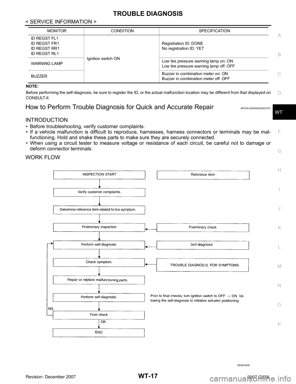
How to Perform Trouble Diagnosis for Quick and Accurate RepairINFOID:0000000003532701
INTRODUCTION
• Before troubleshooting, verify customer complaints.
• If a vehicle malfunction is difficult to reproduce, harnesses, harness connectors or terminals may be mal-
functioning. Hold and shake these parts to make sure they are securely connected.
• When using a circuit tester to measure voltage or resistance of each circuit, be careful not to damage or
deform connector terminals.
WORK FLOW
ID REGST FL1
ID REGST FR1
ID REGST RR1
ID REGST RL1
Ignition switch ONRegistration ID: DONE
No registration ID: YET
WARNING LAMPLow tire pressure warning lamp on: ON
Low tire pressure warning lamp off: OFF
BUZZERBuzzer in combination meter on: ON
Buzzer in combination meter off: OFF MONITOR CONDITION SPECIFICATION
SEIA0100E
Page 3027 of 3061
WW-10
< SERVICE INFORMATION >
FRONT WIPER AND WASHER SYSTEM
Work Flow
INFOID:0000000003533558
1. Confirm the trouble symptom or customer complaint.
2. Understand the system description, refer to WW-3, "
System Description".
3. Perform preliminary inspection, refer to WW-10, "
Preliminary Check".
4. Check symptom and repair or replace the cause of malfunction.
5. Does wiper function operate normally? If it operates normally, GO TO 6. If not, GO TO 4.
6. Inspection End.
Preliminary CheckINFOID:0000000003533559
INSPECTION FOR POWER SUPPLY AND GROUND CIRCUIT
Inspection procedure
1.CHECK FUSE
Check if wiper or washer fuse is blown.
OK or NG
OK >> GO TO 2.
NG >> If fuse is blown, be sure to eliminate cause of blown fuse before installing new fuse.
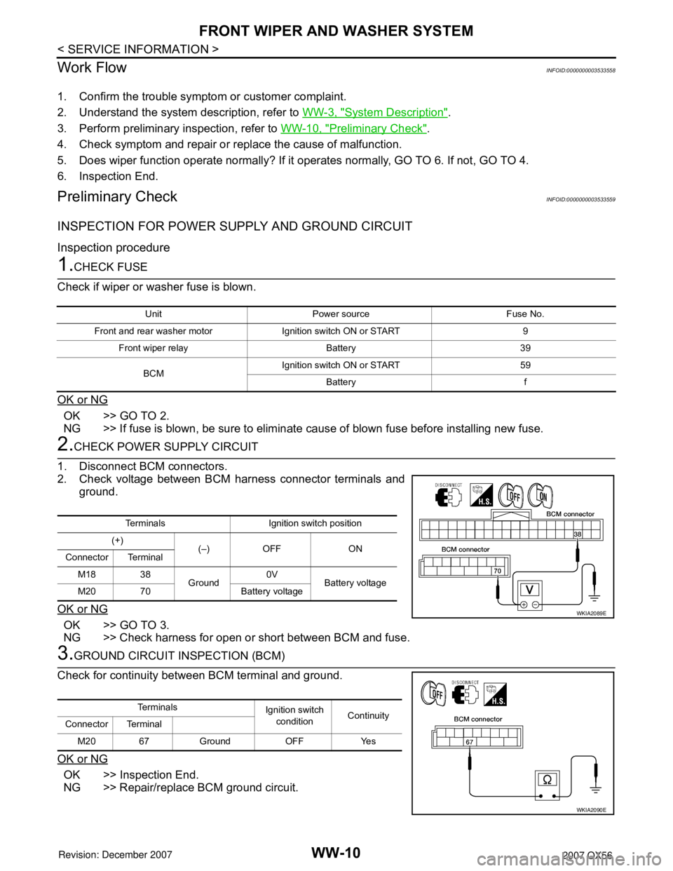
2.CHECK POWER SUPPLY CIRCUIT
1. Disconnect BCM connectors.
2. Check voltage between BCM harness connector terminals and
ground.
OK or NG
OK >> GO TO 3.
NG >> Check harness for open or short between BCM and fuse.
3.GROUND CIRCUIT INSPECTION (BCM)
Check for continuity between BCM terminal and ground.
OK or NG
OK >> Inspection End.
NG >> Repair/replace BCM ground circuit.
Unit Power source Fuse No.
Front and rear washer motor Ignition switch ON or START 9
Front wiper relay Battery 39
BCMIgnition switch ON or START 59
Battery f
Terminals Ignition switch position
(+)
(–) OFF ON
Connector Terminal
M18 38
Ground0V
Battery voltage
M20 70 Battery voltage
WKIA2089E
Te r m i n a l s
Ignition switch
conditionContinuity
Connector Terminal
M20 67 Ground OFF Yes
WKIA2090E
Page 3038 of 3061
FRONT WIPER AND WASHER SYSTEM
WW-21
< SERVICE INFORMATION >
C
D
E
F
G
H
I
J
L
MA
B
WW
N
O
P
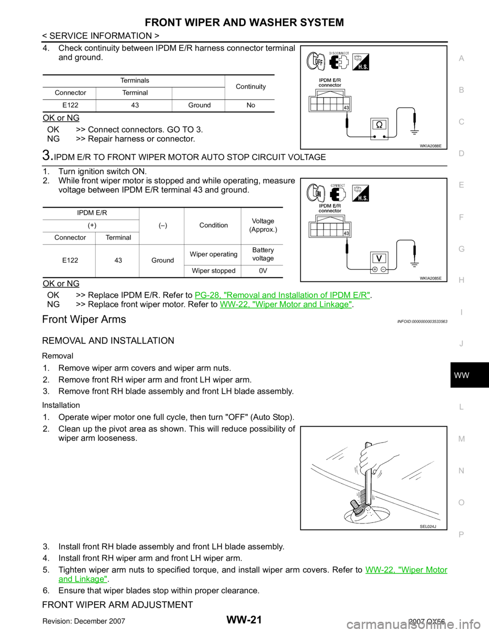
4. Check continuity between IPDM E/R harness connector terminal
and ground.
OK or NG
OK >> Connect connectors. GO TO 3.
NG >> Repair harness or connector.
3.IPDM E/R TO FRONT WIPER MOTOR AUTO STOP CIRCUIT VOLTAGE
1. Turn ignition switch ON.
2. While front wiper motor is stopped and while operating, measure
voltage between IPDM E/R terminal 43 and ground.
OK or NG
OK >> Replace IPDM E/R. Refer to PG-28, "Removal and Installation of IPDM E/R".
NG >> Replace front wiper motor. Refer to WW-22, "
Wiper Motor and Linkage".
Front Wiper ArmsINFOID:0000000003533563
REMOVAL AND INSTALLATION
Removal
1. Remove wiper arm covers and wiper arm nuts.
2. Remove front RH wiper arm and front LH wiper arm.
3. Remove front RH blade assembly and front LH blade assembly.
Installation
1. Operate wiper motor one full cycle, then turn "OFF" (Auto Stop).
2. Clean up the pivot area as shown. This will reduce possibility of
wiper arm looseness.
3. Install front RH blade assembly and front LH blade assembly.
4. Install front RH wiper arm and front LH wiper arm.
5. Tighten wiper arm nuts to specified torque, and install wiper arm covers. Refer to WW-22, "
Wiper Motor
and Linkage".
6. Ensure that wiper blades stop within proper clearance.
FRONT WIPER ARM ADJUSTMENT
Te r m i n a l s
Continuity
Connector Terminal
E122 43 Ground No
WKIA2088E
IPDM E/R
(–) ConditionVo l ta g e
(Approx.) (+)
Connector Terminal
E122 43 GroundWiper operatingBattery
voltage
Wiper stopped 0V
WKIA2085E
SEL024J
Page 3048 of 3061
REAR WIPER AND WASHER SYSTEM
WW-31
< SERVICE INFORMATION >
C
D
E
F
G
H
I
J
L
MA
B
WW
N
O
P
3. Perform the Preliminary Check. Refer to WW-31, "Preliminary Check".
4. Check symptom and repair or replace the cause of malfunction.
5. Does the rear wiper operate normally? If YES: GO TO 6. If NO: GO TO 4.
6. Inspection End.
Preliminary CheckINFOID:0000000003533575
INSPECTION FOR POWER SUPPLY AND GROUND CIRCUIT
Inspection procedure
1.CHECK FUSE
Check if wiper or washer fuse is blown.
OK or NG
OK >> GO TO 2.
NG >> If fuse is blown, be sure to eliminate cause of blown fuse before installing new fuse.
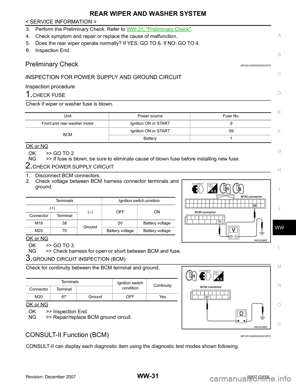
2.CHECK POWER SUPPLY CIRCUIT
1. Disconnect BCM connectors.
2. Check voltage between BCM harness connector terminals and
ground.
OK or NG
OK >> GO TO 3.
NG >> Check harness for open or short between BCM and fuse.
3.GROUND CIRCUIT INSPECTION (BCM)
Check for continuity between the BCM terminal and ground.
OK or NG
OK >> Inspection End.
NG >> Repair/replace BCM ground circuit.
CONSULT-II Function (BCM)INFOID:0000000003533576
CONSULT-II can display each diagnostic item using the diagnostic test modes shown following.
Unit Power source Fuse No.
Front and rear washer motor Ignition ON or START 9
BCMIgnition ON or START 59
Battery f
Terminals Ignition switch position
(+)
(–) OFF ON
Connector Terminal
M18 38
Ground0V Battery voltage
M20 70 Battery voltage Battery voltage
WKIA2089E
Te r m i n a l s
Ignition switch
conditionContinuity
Connector Terminal
M20 67 Ground OFF Yes
WKIA2090E