2007 INFINITI QX56 lock
[x] Cancel search: lockPage 2808 of 3061
SRS-38
< SERVICE INFORMATION >
SPIRAL CABLE
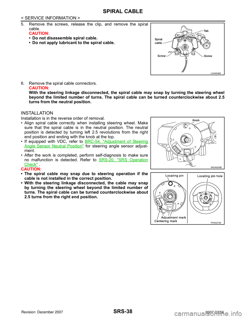
5. Remove the screws, release the clip, and remove the spiral
cable.
CAUTION:
• Do not disassemble spiral cable.
• Do not apply lubricant to the spiral cable.
6. Remove the spiral cable connectors.
CAUTION:
With the steering linkage disconnected, the spiral cable may snap by turning the steering wheel
beyond the limited number of turns. The spiral cable can be turned counterclockwise about 2.5
turns from the neutral position.
INSTALLATION
Installation is in the reverse order of removal.
• Align spiral cable correctly when installing steering wheel. Make
sure that the spiral cable is in the neutral position. The neutral
position is detected by turning left 2.5 revolutions from the right
end position and ending with the knob at the top.
• If equipped with VDC, refer to BRC-54, "
Adjustment of Steering
Angle Sensor Neutral Position" for steering angle sensor adjust-
ment.
• After the work is completed, perform self-diagnosis to make sure
no malfunction is detected. Refer to SRS-20, "
SRS Operation
Check" .
CAUTION:
• The spiral cable may snap due to steering operation if the
cable is not installed in the correct position.
• With the steering linkage disconnected, the cable may snap
by turning the steering wheel beyond the limited number of
turns. The spiral cable can be turned counterclockwise about
2.5 turns from the right end position.
LHIA0036E
WGIA0038E
PHIA0275E
Page 2809 of 3061
FRONT PASSENGER AIR BAG MODULE
SRS-39
< SERVICE INFORMATION >
C
D
E
F
G
I
J
K
L
MA
B
SRS
N
O
P
FRONT PASSENGER AIR BAG MODULE
Removal and InstallationINFOID:0000000003532875
The passenger air bag module originally installed in the vehicle uses direct-connect style harness connectors.
Service replacement passenger air bag modules use tab-locking style harness connectors. If the passenger
air bag module is replaced or if the direct-connect harness connectors are damaged, the vehicle wiring har-
ness must be modified to allow connection of the service replacement passenger air bag module. Refer to
"WIRING HARNESS MODIFICATION" for wiring harness modification procedure.
REMOVAL
CAUTION:
• Do not attempt to repair or replace damaged direct-connect front passenger air bag module connec-
tors. If a direct-connect harness connector is damaged, the front passenger air bag must be
replaced and the wiring harness modified.
• Before servicing SRS, turn the ignition switch off, disconnect both battery cables and wait at least 3
minutes.
• Always work from the side of or under front passenger air bag module.
1. Remove the glove box. Refer to IP-10
.
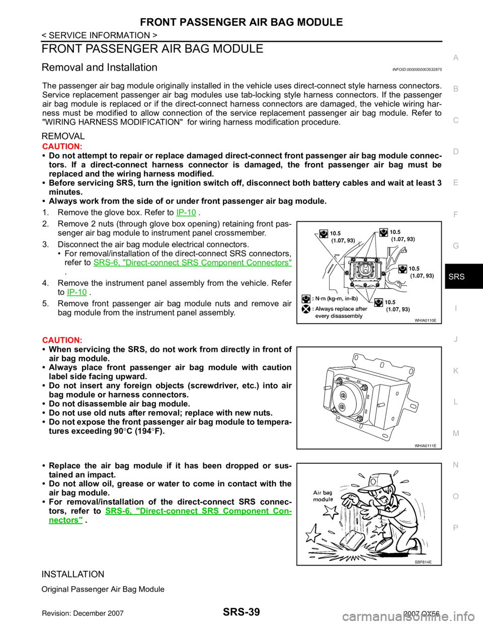
2. Remove 2 nuts (through glove box opening) retaining front pas-
senger air bag module to instrument panel crossmember.
3. Disconnect the air bag module electrical connectors.
• For removal/installation of the direct-connect SRS connectors,
refer to SRS-6, "
Direct-connect SRS Component Connectors"
.
4. Remove the instrument panel assembly from the vehicle. Refer
to IP-10
.
5. Remove front passenger air bag module nuts and remove air
bag module from the instrument panel assembly.
CAUTION:
• When servicing the SRS, do not work from directly in front of
air bag module.
• Always place front passenger air bag module with caution
label side facing upward.
• Do not insert any foreign objects (screwdriver, etc.) into air
bag module or harness connectors.
• Do not disassemble air bag module.
• Do not use old nuts after removal; replace with new nuts.
• Do not expose the front passenger air bag module to tempera-
tures exceeding 90°C (194°F).
• Replace the air bag module if it has been dropped or sus-
tained an impact.
• Do not allow oil, grease or water to come in contact with the
air bag module.
• For removal/installation of the direct-connect SRS connec-
tors, refer to SRS-6, "
Direct-connect SRS Component Con-
nectors" .
INSTALLATION
Original Passenger Air Bag Module
WHIA0110E
WHIA0111E
SBF814E
Page 2810 of 3061
SRS-40
< SERVICE INFORMATION >
FRONT PASSENGER AIR BAG MODULE
Installation is in the reverse order of removal.
• For removal/installation of the direct-connect SRS connectors, refer to SRS-6, "
Direct-connect SRS Compo-
nent Connectors".
CAUTION:
• Always work from the side of or under front passenger air bag module.
• After the work is completed, perform self-diagnosis to check that no malfunction is detected. Refer
to SRS-20, "
SRS Operation Check".
Service Replacement Passenger Air Bag Module
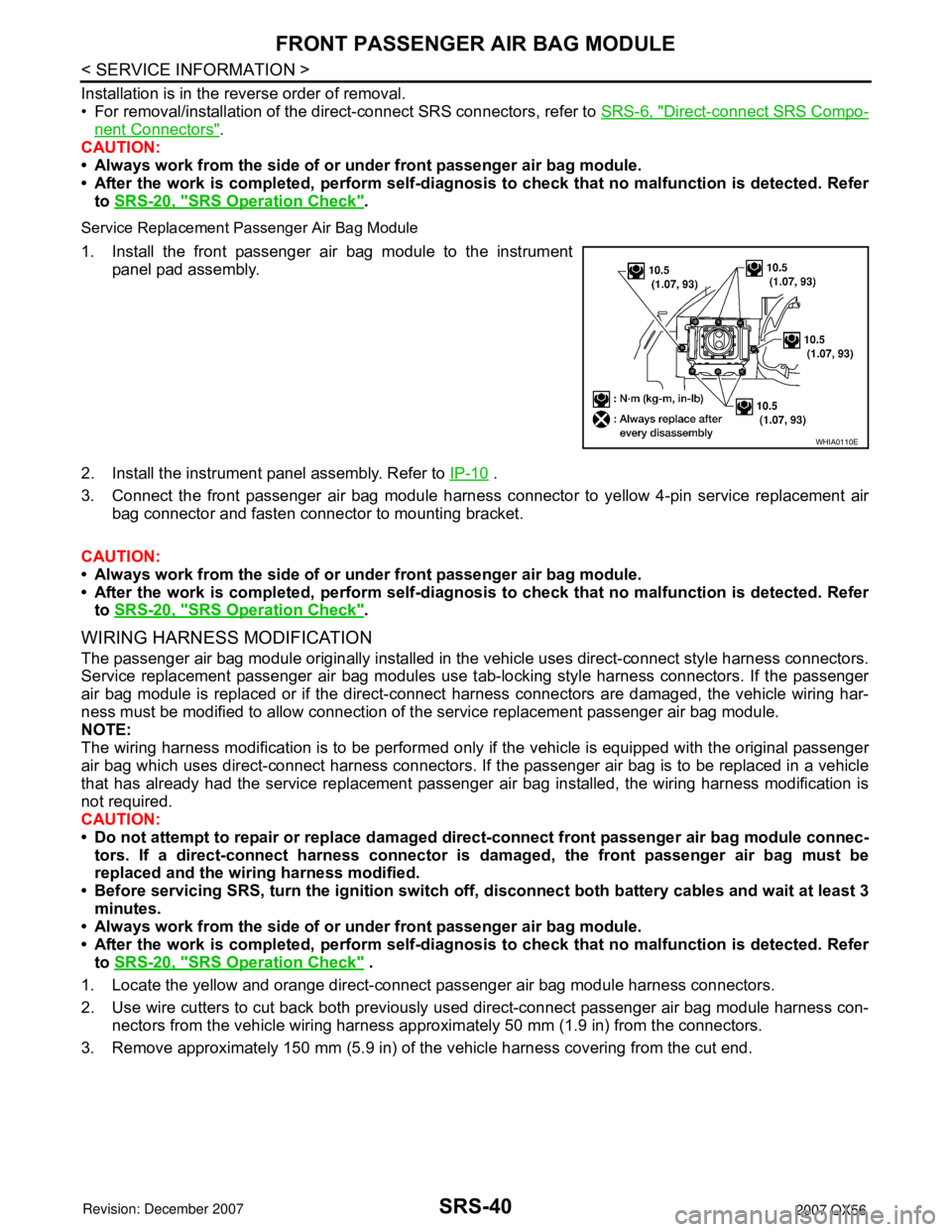
1. Install the front passenger air bag module to the instrument
panel pad assembly.
2. Install the instrument panel assembly. Refer to IP-10
.
3. Connect the front passenger air bag module harness connector to yellow 4-pin service replacement air
bag connector and fasten connector to mounting bracket.
CAUTION:
• Always work from the side of or under front passenger air bag module.
• After the work is completed, perform self-diagnosis to check that no malfunction is detected. Refer
to SRS-20, "
SRS Operation Check".
WIRING HARNESS MODIFICATION
The passenger air bag module originally installed in the vehicle uses direct-connect style harness connectors.
Service replacement passenger air bag modules use tab-locking style harness connectors. If the passenger
air bag module is replaced or if the direct-connect harness connectors are damaged, the vehicle wiring har-
ness must be modified to allow connection of the service replacement passenger air bag module.
NOTE:
The wiring harness modification is to be performed only if the vehicle is equipped with the original passenger
air bag which uses direct-connect harness connectors. If the passenger air bag is to be replaced in a vehicle
that has already had the service replacement passenger air bag installed, the wiring harness modification is
not required.
CAUTION:
• Do not attempt to repair or replace damaged direct-connect front passenger air bag module connec-
tors. If a direct-connect harness connector is damaged, the front passenger air bag must be
replaced and the wiring harness modified.
• Before servicing SRS, turn the ignition switch off, disconnect both battery cables and wait at least 3
minutes.
• Always work from the side of or under front passenger air bag module.
• After the work is completed, perform self-diagnosis to check that no malfunction is detected. Refer
to SRS-20, "
SRS Operation Check" .
1. Locate the yellow and orange direct-connect passenger air bag module harness connectors.
2. Use wire cutters to cut back both previously used direct-connect passenger air bag module harness con-
nectors from the vehicle wiring harness approximately 50 mm (1.9 in) from the connectors.
3. Remove approximately 150 mm (5.9 in) of the vehicle harness covering from the cut end.
WHIA0110E
Page 2828 of 3061
TF-6
< SERVICE INFORMATION >
PREPARATION
PREPARATION
Special Service ToolINFOID:0000000003532510
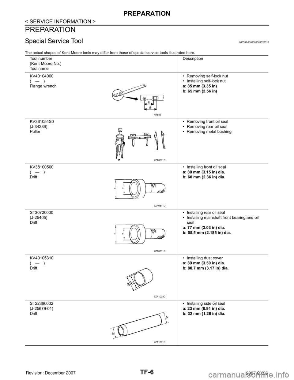
The actual shapes of Kent-Moore tools may differ from those of special service tools illustrated here.
Tool number
(Kent-Moore No.)
Tool nameDescription
KV40104000
(—)
Flange wrench• Removing self-lock nut
• Installing self-lock nut
a: 85 mm (3.35 in)
b: 65 mm (2.56 in)
KV381054S0
(J-34286)
Puller• Removing front oil seal
• Removing rear oil seal
• Removing metal bushing
KV38100500
(—)
Drift• Installing front oil seal
a: 80 mm (3.15 in) dia.
b: 60 mm (2.36 in) dia.
ST30720000
(J-25405)
Drift• Installing rear oil seal
• Installing mainshaft front bearing and oil
seal
a: 77 mm (3.03 in) dia.
b: 55.5 mm (2.185 in) dia.
KV40105310
(—)
Drift• Installing dust cover
a: 89 mm (3.50 in) dia.
b: 80.7 mm (3.17 in) dia.
ST22360002
(J-25679-01)
Drift• Installing side oil seal
a: 23 mm (0.91 in) dia.
b: 32 mm (1.26 in) dia.
NT659
ZZA0601D
ZZA0811D
ZZA0811D
ZZA1003D
ZZA1091D
Page 2839 of 3061

ALL-MODE 4WD SYSTEM
TF-17
< SERVICE INFORMATION >
C
E
F
G
H
I
J
K
L
MA
B
TF
N
O
P
*: After 2.5 seconds have elapsed.
• 4WD shift switch, PNP switch, Neutral-4LO switch, vehicle speed sensor and throttle position sensor are
used in conjunction with the transfer motor.
WAIT DETECTION SWITCH
• The wait detection switch operates when there is “circulating” torque produced in the propeller shaft (L→H)
or when there is a phase difference between 2-4 sleeve and clutch drum (H→L). After the release of the “cir-
culating” torque, the wait detection switch helps provide the 4WD lock gear (clutch drum) shifts. A difference
may occur between the operation of the 4WD shift switch and actual drive mode. At this point, the wait
detection switch senses an actual drive mode.
• The wait detection switch operates as follows.
- 4WD lock gear (clutch drum) locked: ON
- 4WD lock gear (clutch drum) released: OFF
• The wait detection switch senses an actual drive mode and the 4WD shift indicator lamp indicates the vehi-
cle drive mode.
NEUTRAL-4LO SWITCH
The neutral-4LO switch detects that transfer gear is in neutral or 4LO (or shifting from neutral to 4LO) condi-
tion by L-H shift fork position.
AT P S W I T C H
ATP switch detects if transfer gear is in a neutral condition by L-H shift fork position.
NOTE:
Transfer gear may be in a neutral condition in 4H-4LO.
2-4WD SHIFT SOLENOID VALVE
The 2-4WD shift solenoid valve operates to apply oil pressure to the wet-multiplate clutch, depending on the
drive mode. The driving force is transmitted to the front wheels through the clutch so the vehicle is set in the
4WD mode. Setting the vehicle in the 2WD mode requires no pressure buildup. In other words, pressure force
applied to the wet-multiplate clutch becomes zero.
CLUTCH PRESSURE SOLENOID VALVE
The clutch pressure solenoid valve distributes torque (front and rear) in AUTO mode.
4H (LOCK) and 4LO“N” position 0 — ON
“P” position 00 - 0.07/8 OFF*
0.07/8 - 1/8 HOLD
1/8 - MAX ON
Other than “R” position0 < VSS ≤ 50 km/h (31 MPH)
— ON
50 km/h (31 MPH) < VSS < 55
km/h (34 MPH) HOLD
55 km/h (34 MPH) ≤ VSS OFF
“R” position — — ON
“R” position — — ON
AUTO“P” or “N” position00 - 0.07/8 OFF*
0.07/8 - 1/8 HOLD
1/8 - MAX ON
0 < VSS ≤ 50 km/h (31 MPH)
— ON
50 km/h (31 MPH) < VSS < 55
km/h (34 MPH) HOLD
55 km/h (34 MPH) ≤ VSS OFF
Other than “R”, "P" and "N"
position0 < VSS ≤ 50 km/h (31 MPH)
— ON
50 km/h (31 MPH) < VSS < 55
km/h (34 MPH) HOLD
55 km/h (34 MPH) ≤ VSS OFF 4WD shift switch A/T selector lever positionVehicle speed
(VSS)Accelerator pedal positionMotor relay drive
command
Page 2841 of 3061
ALL-MODE 4WD SYSTEM
TF-19
< SERVICE INFORMATION >
C
E
F
G
H
I
J
K
L
MA
B
TF
N
O
P
*: When 4WD warning lamp is ON, all the 4WD shift indicator lamps turn OFF.
ATP WARNING LAMP
Even if A/T selector lever is in “P” position, vehicle may move because A/T parking mechanism does not oper-
ate when transfer is under neutral condition. ATP warning lamp is turned on so as to indicate this condition to
the driver.
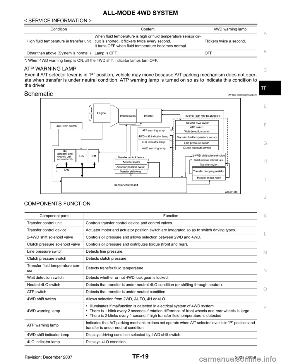
SchematicINFOID:0000000003532518
COMPONENTS FUNCTION
High fluid temperature in transfer unitWhen fluid temperature is high or fluid temperature sensor cir-
cuit is shorted, it flickers twice every second.
It turns OFF when fluid temperature becomes normal.Flickers twice a second.
Other than above (System is normal.) Lamp is OFF. OFFCondition Content 4WD warning lamp
WDIA0164E
Component parts Function
Transfer control unit Controls transfer control device and control valves.
Transfer control device Actuator motor and actuator position switch are integrated so as to switch driving types.
2-4WD shift solenoid valve Controls oil pressure and allows selection between 2WD and 4WD.
Clutch pressure solenoid valve Controls oil pressure and distributes torque (front and rear).
Line pressure switch Detects line pressure.
Clutch pressure switch Detects clutch pressure.
Transfer fluid temperature sen-
sorDetects transfer fluid temperature.
Wait detection switch Detects whether or not 4WD lock gear is locked.
Neutral-4LO switch Detects that transfer is under neutral-4LO condition (or shifting through neutral).
ATP switch Detects that transfer is under neutral condition.
4WD shift switch Allows selection from 2WD, AUTO, 4H or 4LO.
4WD warning lamp• Illuminates if malfunction is detected in electrical system of 4WD system.
• There is 1 blink every 2 seconds if rotation difference of front wheels and rear wheels is large.
• There is 2 blinks every 1 second if high transfer fluid temperature is detected.
AT P w a r n i n g l a m pIndicates that A/T parking mechanism does not operate when A/T selector lever is in “P” position and
transfer is under neutral condition.
4WD shift indicator lamp Displays driving condition selected by 4WD shift switch.
4LO indicator lamp Displays 4LO condition.
Page 2857 of 3061

TROUBLE DIAGNOSIS
TF-35
< SERVICE INFORMATION >
C
E
F
G
H
I
J
K
L
MA
B
TF
N
O
P
• Heavy tight-corner braking symptom occurs when vehicle is driven in the following conditions: 4WD shift
switch is "4H" or "4LO", steering wheel is turned fully to either side.
Transfer Control Unit Input/Output Signal Reference ValueINFOID:0000000003532526
TRANSFER CONTROL UNIT INSPECTION TABLE
Specifications with CONSULT-II
Monitored item [Unit] Content Condition Display value
VHCL/S SEN·FR [km/h]
or [mph]Front wheel speedVehicle stopped 0 km/h (0 MPH)
Vehicle running
CAUTION:
Check air pressure of tire under standard condition.Approximately
equal to the indica-
tion on speedome-
ter (Inside of
±10%)
VHCL/S SEN·RR [km/h]
or [mph]Rear wheel speedVehicle stopped 0 km/h (0 MPH)
Vehicle running
CAUTION:
Check air pressure of tire under standard condition.Approximately
equal to the indica-
tion on speedome-
ter (Inside of
±10%)
ENGINE SPEED [rpm] Engine speedEngine stopped
(Engine speed: Less than 400 rpm)0 rpm
Engine running
(Engine speed: 400 rpm or more)Approximately
equal to the indica-
tion on tachometer
THRTL POS SEN [V]Accelerator pedal posi-
tion (APP) sensor signal
voltageAccelerator pedal: Release Approx. 0.5V
Accelerator pedal: Fully depressed Approx. 4.0V
FLUID TEMP SE [V]Transfer fluid tempera-
ture signal voltageTransfer fluid temperature approx. 20 - 80°C (68 - 176°F) Approx. 1.1 - 0.3V
BATTERY VOLT [V]Power supply voltage for
transfer control unitIgnition switch: ON Battery voltage
2WD SWITCH [ON/OFF]Input condition from 4WD
shift switch4WD shift switch: 2WD ON
4WD shift switch: AUTO, 4H or 4LO OFF
AUTO SWITCH [ON/
OFF]Input condition from 4WD
shift switch4WD shift switch: AUTO ON
4WD shift switch: 2WD, 4H or 4LO OFF
LOCK SWITCH [ON/
OFF]Input condition from 4WD
shift switch4WD shift switch: 4H ON
4WD shift switch: 2WD, AUTO or 4LO OFF
4L SWITCH [ON/OFF]Input condition from 4WD
shift switch4WD shift switch: 4LO ON
4WD shift switch: 2WD, AUTO or 4H OFF
N POSI SW TF [ON/
OFF]Condition of neutral-4LO
switch• Vehicle stopped
• Engine running
• A/T selector lever “N” posi-
tion
• Brake pedal depressed4WD shift switch: 2WD,
AUTO or 4HOFF
4WD shift switch: 4H to
4LO (While actuator mo-
tor is operating.)OFF → ON
4WD shift switch: 4LO to
4H (While actuator motor
is operating.)ON → OFF
4WD shift switch: 4LO ON
Page 2858 of 3061
![INFINITI QX56 2007 Factory Service Manual TF-36
< SERVICE INFORMATION >
TROUBLE DIAGNOSIS
ATP SWITCH [ON/OFF] Condition of ATP switch• Vehicle stopped
• Engine running
• A/T selector lever “N”
• Brake pedal depressed4WD shift swit INFINITI QX56 2007 Factory Service Manual TF-36
< SERVICE INFORMATION >
TROUBLE DIAGNOSIS
ATP SWITCH [ON/OFF] Condition of ATP switch• Vehicle stopped
• Engine running
• A/T selector lever “N”
• Brake pedal depressed4WD shift swit](/manual-img/42/57029/w960_57029-2857.png)
TF-36
< SERVICE INFORMATION >
TROUBLE DIAGNOSIS
ATP SWITCH [ON/OFF] Condition of ATP switch• Vehicle stopped
• Engine running
• A/T selector lever “N”
• Brake pedal depressed4WD shift switch
: 4H to 4LO or 4LO to 4H
(While actuator motor is
operating.) ON
Except the above OFF
WAIT DETCT SW [ON/
OFF]Condition of wait detec-
tion switch• Vehicle stopped
• Engine running
• A/T selector lever “N” posi-
tion
• Brake pedal depressed4WD shift switch: 2WD,
AUTO or 4HOFF
4WD shift switch: 4H to
4LO (While actuator mo-
tor is operating.)OFF → ON
4WD shift switch: 4LO to
4H (While actuator motor
is operating.)ON → OFF
4WD shift switch: 4LO ON
LINE PRES SW [ON/
OFF]Condition of line pres-
sure switch• A/T selector lever “D” position
• 4WD shift switch: 2WD, AUTO or 4HON
• Except the above
• The vehicle has been left at
room temperature for 5
minutes and more with ig-
nition switch in “OFF” posi-
tion.• Ignition switch: ON
• A/T selector lever: “P”
or "N" position
• 4WD shift switch: other
than AUTOOFF
CL PRES SW [ON / OFF]Condition of clutch pres-
sure switch• Vehicle stopped
• Engine running
• A/T selector lever “D” position
• 4WD shift switch: AUTO or 4H (“Wait” function is not op-
erating.)ON
• Vehicle stopped
• Engine running
• 4WD shift switch: 2WD (“Wait” function is not operat-
ing.)OFF
N POSI SW AT [ON/
OFF]Input condition from A/T
PNP switch• Vehicle stopped
• Engine running
• Brake pedal depressedA/T selector lever posi-
tion: NON
Except the above OFF
R POSI SW AT [ON/
OFF]Input condition from A/T
PNP switch• Vehicle stopped
• Engine running
• Brake pedal depressedA/T selector lever posi-
tion: RON
Except the above OFF
P POSI SW AT [ON/OFF]Input condition from A/T
PNP switch• Vehicle stopped
• Engine running
• Brake pedal depressedA/T selector lever posi-
tion: PON
Except the above OFF
ABS OPER SW [ON/
OFF]Condition of ABS operat-
ingABS is operating. ON
ABS is not operating. OFF
VDC OPER SW [ON/
OFF]Condition of VDC operat-
ingVDC is operating. ON
VDC is not operating. OFF
TCS OPER SW [ON/
OFF]Condition of TCS operat-
ingTCS is operating. ON
TCS is not operating. OFF
THROTTLE POSI [0.0/8]Condition of throttle
openingWhen depressing accelerator pedal
(Value rises gradually in response to throttle position.)0.0/8 - 8.0/8
4WD MODE [AUTO/
LOCK/2WD/4L]Control status of 4WD
(Output condition of 4WD
shift indicator lamp and
4LO indicator lamp)• Vehicle stopped
• Engine running
• A/T selector lever “N” posi-
tion
• Brake pedal depressed4WD shift switch: 2WD 2WD
4WD shift switch: AUTO AUTO
4WD shift switch: 4H LOCK
4WD shift switch: 4LO 4L Monitored item [Unit] Content Condition Display value