2007 INFINITI QX56 check oil
[x] Cancel search: check oilPage 2626 of 3061
RSU-36
< SERVICE INFORMATION >
REAR LOWER LINK & COIL SPRING
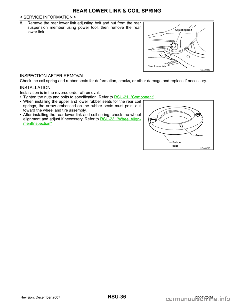
8. Remove the rear lower link adjusting bolt and nut from the rear
suspension member using power tool, then remove the rear
lower link.
INSPECTION AFTER REMOVAL
Check the coil spring and rubber seats for deformation, cracks, or other damage and replace if necessary.
INSTALLATION
Installation is in the reverse order of removal.
• Tighten the nuts and bolts to specification. Refer to RSU-21, "
Component" .
• When installing the upper and lower rubber seats for the rear coil
springs, the arrow embossed on the rubber seats must point out
toward the wheel and tire assembly.
• After installing the rear lower link and coil spring, check the wheel
alignment and adjust if necessary. Refer to RSU-23, "
Wheel Align-
mentInspection"
LEIA0009E
LEIA0076E
Page 2636 of 3061
SB-2
< SERVICE INFORMATION >
PRECAUTIONS
SERVICE INFORMATION
PRECAUTIONS
Precaution for Supplemental Restraint System (SRS) "AIR BAG" and "SEAT BELT
PRE-TENSIONER"
INFOID:0000000003532841
The Supplemental Restraint System such as “AIR BAG” and “SEAT BELT PRE-TENSIONER”, used along
with a front seat belt, helps to reduce the risk or severity of injury to the driver and front passenger for certain
types of collision. This system includes seat belt switch inputs and dual stage front air bag modules. The SRS
system uses the seat belt switches to determine the front air bag deployment, and may only deploy one front
air bag, depending on the severity of a collision and whether the front occupants are belted or unbelted.
Information necessary to service the system safely is included in the SRS and SB section of this Service Man-
ual.
WARNING:
• To avoid rendering the SRS inoperative, which could increase the risk of personal injury or death in
the event of a collision which would result in air bag inflation, all maintenance must be performed by
an authorized NISSAN/INFINITI dealer.
• Improper maintenance, including incorrect removal and installation of the SRS, can lead to personal
injury caused by unintentional activation of the system. For removal of Spiral Cable and Air Bag
Module, see the SRS section.
• Do not use electrical test equipment on any circuit related to the SRS unless instructed to in this
Service Manual. SRS wiring harnesses can be identified by yellow and/or orange harnesses or har-
ness connectors.
Precaution for Seat Belt ServiceINFOID:0000000003532842
CAUTION:
• Before removing the seat belt pre-tensioner assembly, turn the ignition switch OFF, disconnect both
battery cables and wait at least 3 minutes.
• After replacing or reinstalling seat belt pre-tensioner assembly, or reconnecting seat belt pre-ten-
sioner assembly connector, make sure entire SRS operates properly. Refer to SRS-20, "
SRS Opera-
tion Check".
• Do not disassemble buckle or seat belt assembly.
• Do not reuse seat belt anchor bolts after removal. Replace with new ones.
• Replace anchor bolts if they are deformed or worn out.
• Never oil tongue and buckle.
• If any component of seat belt assembly is questionable, do not repair. Replace the whole seat belt
assembly.
• If webbing is cut, frayed, or damaged, replace seat belt assembly.
• When replacing seat belt assembly, use a genuine NISSAN seat belt assembly.
AFTER A COLLISION
WARNING:
• Inspect all seat belt assemblies including retractors and attaching hardware after any collision.
• NISSAN recommends that all seat belt assemblies in use during a collision be replaced unless the
collision was minor and the belts show no damage and continue to operate properly. Failure to do so
could result in serious personal injury in an accident. Seat belt assemblies not in use during a colli-
sion should also be replaced if either damage or improper operation is noted. Seat belt pre-tensioner
should be replaced even if the seat belts are not in use during a frontal collision in which the air bags
are deployed.
Replace any seat belt assembly (including anchor bolts) if:
• The seat belt was in use at the time of a collision (except for minor collisions and the belts, retractors and
buckles show no damage and continue to operate properly).
• The seat belt was damaged in an accident. (i.e., torn webbing, bent retractor or guide, etc.)
• The seat belt attaching point was damaged in an accident. Inspect the seat belt attaching area for damage
or distortion and repair as necessary before installing a new seat belt assembly.
• Anchor bolts are deformed or worn out.
• The seat belt pre-tensioner should be replaced even if the seat belts are not in use during the collision in
which the air bags are deployed.
Page 2675 of 3061
PRECAUTIONS
SE-3
< SERVICE INFORMATION >
C
D
E
F
G
H
J
K
L
MA
B
SE
N
O
P
SERVICE INFORMATION
PRECAUTIONS
Precaution for Supplemental Restraint System (SRS) "AIR BAG" and "SEAT BELT
PRE-TENSIONER"
INFOID:0000000003533149
The Supplemental Restraint System such as “AIR BAG” and “SEAT BELT PRE-TENSIONER”, used along
with a front seat belt, helps to reduce the risk or severity of injury to the driver and front passenger for certain
types of collision. This system includes seat belt switch inputs and dual stage front air bag modules. The SRS
system uses the seat belt switches to determine the front air bag deployment, and may only deploy one front
air bag, depending on the severity of a collision and whether the front occupants are belted or unbelted.
Information necessary to service the system safely is included in the SRS and SB section of this Service Man-
ual.
WARNING:
• To avoid rendering the SRS inoperative, which could increase the risk of personal injury or death in
the event of a collision which would result in air bag inflation, all maintenance must be performed by
an authorized NISSAN/INFINITI dealer.
• Improper maintenance, including incorrect removal and installation of the SRS, can lead to personal
injury caused by unintentional activation of the system. For removal of Spiral Cable and Air Bag
Module, see the SRS section.
• Do not use electrical test equipment on any circuit related to the SRS unless instructed to in this
Service Manual. SRS wiring harnesses can be identified by yellow and/or orange harnesses or har-
ness connectors.
Precaution for WorkINFOID:0000000003533150
• When removing or disassembling each component, be careful not to damage or deform it. If a component
may be subject to interference, be sure to protect it with a shop cloth.
• When removing (disengaging) components with a screwdriver or similar tool, be sure to wrap the component
with a shop cloth or vinyl tape to protect it.
• Protect the removed parts with a shop cloth and keep them.
• Replace a deformed or damaged clip.
• If a part is specified as a non-reusable part, always replace it with new one.
• Be sure to tighten bolts and nuts securely to the specified torque.
• After re-installation is completed, be sure to check that each part works normally.
• Follow the steps below to clean components.
- Water soluble foul: Dip a soft cloth into lukewarm water, and wring the water out of the cloth to wipe the
fouled area.
Then rub with a soft and dry cloth.
- Oily foul: Dip a soft cloth into lukewarm water with mild detergent (concentration: within 2 to 3%), and wipe
the fouled area.
Then dip a cloth into fresh water, and wring the water out of the cloth to wipe the detergent off. Then rub with
a soft and dry cloth.
• Do not use organic solvent such as thinner, benzene, alcohol, or gasoline.
• For genuine leather seats, use a genuine leather seat cleaner.
Page 2806 of 3061
SRS-36
< SERVICE INFORMATION >
DRIVER AIR BAG MODULE
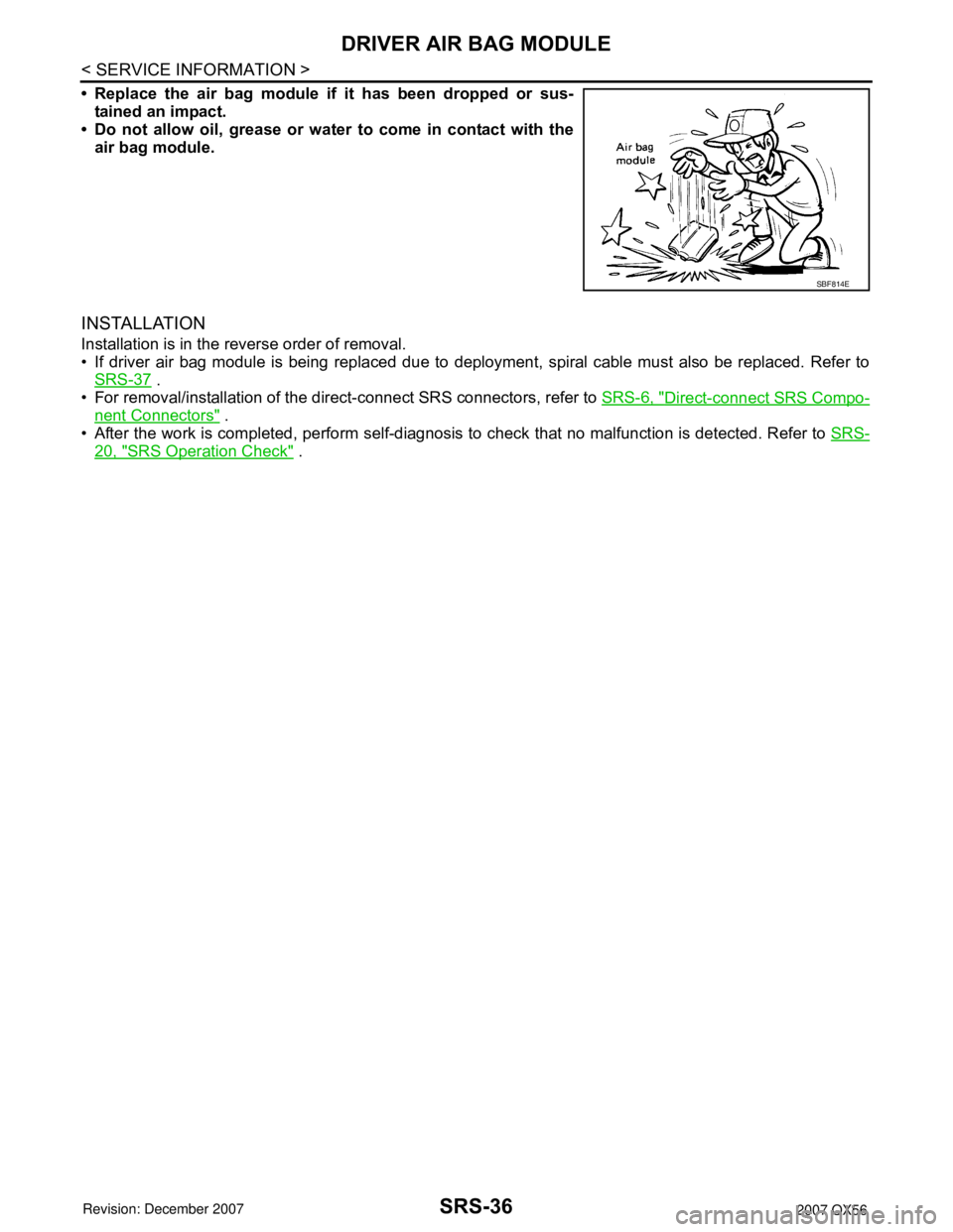
• Replace the air bag module if it has been dropped or sus-
tained an impact.
• Do not allow oil, grease or water to come in contact with the
air bag module.
INSTALLATION
Installation is in the reverse order of removal.
• If driver air bag module is being replaced due to deployment, spiral cable must also be replaced. Refer to
SRS-37
.
• For removal/installation of the direct-connect SRS connectors, refer to SRS-6, "
Direct-connect SRS Compo-
nent Connectors" .
• After the work is completed, perform self-diagnosis to check that no malfunction is detected. Refer to SRS-
20, "SRS Operation Check" .
SBF814E
Page 2840 of 3061

TF-18
< SERVICE INFORMATION >
ALL-MODE 4WD SYSTEM
LINE PRESSURE SWITCH
• With the transfer system design, control of the oil pressure provides the transmission of drive torque to the
front wheels. The main pressure to control the oil pressure is referred to as the line pressure.
• The line pressure switch determines whether or not adequate line pressure has built up under different oper-
ating conditions.
• The line pressure switch turns ON when line pressure is produced.
• The line pressure switch senses line pressure abnormalities and turns the 4WD warning lamp ON.
CLUTCH PRESSURE SWITCH
• The clutch pressure switch determines whether or not adequate clutch pressure has built up under different
operating conditions.
• The clutch pressure switch turns ON when clutch pressure is produced.
• The clutch pressure switch senses clutch pressure abnormalities and turns the 4WD warning lamp ON.
TRANSFER FLUID TEMPERATURE SENSOR
The transfer temperature sensor detects the transfer fluid temperature and sends a signal to the transfer con-
trol unit.
TRANSFER CONTROL UNIT
• Transfer control unit controls transfer control device by input signals of each sensor and each switch.
• Self-diagnosis can be done.
TRANSFER CONTROL DEVICE
The transfer control device changes the state of transfer assembly between 2WD, AUTO, 4H⇔4LO with the
2WD, AUTO, 4H and 4LO signals of 4WD shift switch.
NOTE:
• To shift between 4H⇔4LO, stop the vehicle, depress the brake pedal and shift the transmission selector to
the "N" position. Depress and turn the 4WD shift switch. The shift switch will not shift to the desired mode if
the transmission is not in "N" or the vehicle is moving. The 4LO indicator lamp will be lit when the 4LO is
engaged.
• Actuator motor and actuator position switch are integrated.
4WD SHIFT SWITCH AND INDICATOR LAMP
4WD Shift Switch
The 4WD shift switch allows selection from 2WD, AUTO, 4H or 4LO.
4WD Shift Indicator Lamp
• Displays driving conditions selected by 4WD shift switch with 2WD, AUTO and 4H indicators while engine is
running. (When 4WD warning lamp is turned on, all 4WD shift indicator lamps are turned off.)
• Turns ON for approximately 1 second when ignition switch is turned ON, for purpose of lamp check.
4LO Indicator Lamp
• Displays 4LO condition while engine is running. 4LO indicator lamp flashes if transfer gear does not shift
completely under 2WD, AUTO, 4H⇔4LO. (When 4WD warning lamp is turned on, 4LO indicator lamp is
turned off.)
• Turns ON for approximately 1 second when ignition switch is turned ON, for purpose of lamp check.
4WD WARNING LAMP
Turns ON or FLASH when there is a malfunction in 4WD system.
Also turns ON when ignition switch is turned ON, for purpose of lamp check. Turns OFF for approximately 1
second after the engine starts if system is normal.
4WD Warning Lamp Indication
Condition Content 4WD warning lamp
During self-diagnosis Indicates the malfunction position by number of flickers. Flickers at malfunction mode.
Lamp check*Checks the lamp by turning ON during engine starting. After
engine starts, it turns OFF if there are no malfunctions.ON
Malfunction in 4WD system*Turns ON to indicate malfunction. When ignition switch is
turned to “OFF” or the malfunction is corrected, it turns OFF.ON
When vehicle is driven with different
diameters of front and rear tiresFlickers once every 2 seconds.
Turns OFF when ignition switch is “OFF”.Flickers once every 2 sec-
onds.
Page 2866 of 3061
![INFINITI QX56 2007 Factory Service Manual TF-44
< SERVICE INFORMATION >
TROUBLE DIAGNOSIS
CAUTION:
• If “CAN COMM CIRCUIT [U1000]” is displayed with other DTCs, first perform the trouble diagnosis for CAN communication
line.
• If “V INFINITI QX56 2007 Factory Service Manual TF-44
< SERVICE INFORMATION >
TROUBLE DIAGNOSIS
CAUTION:
• If “CAN COMM CIRCUIT [U1000]” is displayed with other DTCs, first perform the trouble diagnosis for CAN communication
line.
• If “V](/manual-img/42/57029/w960_57029-2865.png)
TF-44
< SERVICE INFORMATION >
TROUBLE DIAGNOSIS
CAUTION:
• If “CAN COMM CIRCUIT [U1000]” is displayed with other DTCs, first perform the trouble diagnosis for CAN communication
line.
• If “VHCL SPEED SEN·AT [P1808]”, “ABS OP SIG [P1830]”, “VDC OP SIG [P1831]” or “TCS OP SIG [P1832]” is displayed, first
perform the trouble diagnosis for ABS system.
• If “VHCL SPEED SEN·AT [P1808]”, is displayed, first perform the trouble diagnosis for A/T system.
NOTE:
• If "SHIFT ACT POSI SW [P1818]" or “SHIFT ACT CIR [P1819]” is displayed, first erase self-diagnostic results. ("SHIFT ACT POSI SW
[P1818]" or “SHIFT ACT CIR [P1819]” may be displayed after installing transfer control unit or transfer assembly.)
• If “CL PRES SW [P1827]” or “LINE PRES SW [P1828]” is displayed only while driving in reverse, check the continuity of “R” position
on A/T PNP switch. When there is nothing wrong with the electrical system, check the hydraulic system.
How to Erase Self-diagnostic Results
1. Perform applicable inspection of malfunctioning item and then repair or replace.
SHIFT ACT CIR
[P1819]• Transfer control device actuator circuit is shorted or open. (Mal-
functions are detected when transfer shift relay circuit is open/
shorted or relay monitor circuit is open/shorted.)
• Malfunction occurs in transfer control device drive circuit.
• Malfunction is detected in transfer shut off relay.TF-72, "Transfer Control Device"
Malfunction is detected in transfer shut off relay.TF-51, "Power Supply Circuit for
Transfer Control Unit"
ENGINE SPEED SIG
[P1820]• Malfunction is detected in engine speed signal that is output from
ECM through CAN communication.
• Improper signal is input while driving.TF-76, "Engine Speed Signal
(ECM)"
DUTY SOLENOID
[P1822]• Proper voltage is not applied to clutch pressure solenoid valve
due to open or short circuit.TF-76, "Clutch Pressure Sole-
noid"
2-4WD SOLENOID
[P1823]• Proper voltage is not applied to 2-4WD solenoid valve due to open
or short circuit.TF-80, "2-4WD Solenoid"
MOTOR RELAY
[P1824]• Motor does not operate properly due to open or short circuit in
transfer motor or motor relay.TF-84, "Transfer Motor"
OIL TEMP SEN
[P1826]• Signal voltage from fluid temperature sensor is abnormally high
(Transfer fluid temperature is abnormally low) while driving.TF-90, "Transfer Fluid Tempera-
ture"
CLUTCH PRES SW
[P1827]• Improper signal from clutch pressure switch is input due to open or
short circuit.
• Malfunction occurs in clutch pressure switch or hydraulic circuit.TF-92, "Clutch Pressure Switch"
LINE PRES SW
[P1828]• Improper signal from line pressure switch is input due to open or
short circuit.
• Malfunction occurs in line pressure switch or hydraulic circuit.TF-94, "Line Pressure Switch"
THROTTLE POSI SEN
[P1829]• Malfunction is detected in accelerator pedal position signal that is
output from ECM through CAN communication.
• Signal voltage from accelerator pedal position sensor is abnormal-
ly high or low.TF-97, "Throttle Position Signal
(ECM)"
ABS OP SIG
[P1830]• Malfunction is detected in ABS operation signal that is output from
ABS actuator and electric unit (control unit) through CAN commu-
nication.TF-97, "ABS Operation Signal
(ABS)"
VDC OP SIG
[P1831]• Malfunction is detected in VDC operation signal that is output from
ABS actuator and electric unit (control unit) through CAN commu-
nication.TF-98, "VDC Operation Signal
(ABS)"
TCS OP SIG
[P1832]• Malfunction is detected in TCS operation signal that is output from
ABS through CAN communication.TF-98, "TCS Operation Signal
(ABS)"
CAN COMM CIRCUIT
[U1000]• Malfunction has been detected from CAN communication line.TF-99, "CAN Communication
Line"
NO DTC IS DETECTED.
FURTHER TESTING MAY
BE REQUIRED.• No NG item has been detected. — Items (CONSULT-II screen
terms)Diagnostic item is detected when... Check item
Page 2939 of 3061

FRONT OIL SEAL
TF-117
< SERVICE INFORMATION >
C
E
F
G
H
I
J
K
L
MA
B
TF
N
O
P
1. Install the new oil seal until it is flush with the end face of the
front case using Tool.
CAUTION:
• Do not reuse oil seal.
• Apply petroleum jelly to oil seal.
2. Align the matching mark of the front drive shaft with the match-
ing mark of the companion flange, then install the companion
flange.
3. Install the new self-lock nut. Tighten to the specified torque
using Tool. Refer to TF-128, "
Disassembly and Assembly".
CAUTION:
Do not reuse self-lock nut.
4. Install the front propeller shaft. Refer to PR-4, "
Removal and
Installation".
5. Refill the transfer with fluid and check fluid level. Refer to TF-11
.
6. Check the transfer for fluid leakage. Refer to TF-11, "
Inspec-
tion". Tool number : KV38100500 ( — )
SDIA2662E
SDIA2658E
Tool number : KV40104000 ( — )
LDIA0147E
Page 2941 of 3061
REAR OIL SEAL
TF-119
< SERVICE INFORMATION >
C
E
F
G
H
I
J
K
L
MA
B
TF
N
O
P
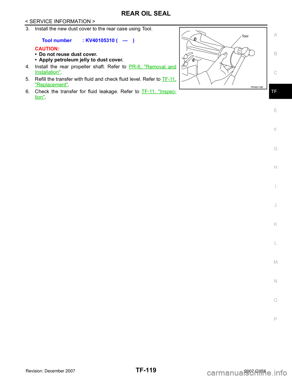
3. Install the new dust cover to the rear case using Tool.
CAUTION:
• Do not reuse dust cover.
• Apply petroleum jelly to dust cover.
4. Install the rear propeller shaft. Refer to PR-8, "
Removal and
Installation".
5. Refill the transfer with fluid and check fluid level. Refer to TF-11,
"Replacement".
6. Check the transfer for fluid leakage. Refer to TF-11, "
Inspec-
tion". Tool number : KV40105310 ( — )
PDIA0116E