2007 INFINITI QX56 check oil
[x] Cancel search: check oilPage 2569 of 3061
RFD-12
< SERVICE INFORMATION >
SIDE OIL SEAL
Check the differential gear oil level after installation. Refer to RFD-8, "Checking Differential Gear
Oil".
Page 2574 of 3061

REAR FINAL DRIVE ASSEMBLY
RFD-17
< SERVICE INFORMATION >
C
E
F
G
H
I
J
K
L
MA
B
RFD
N
O
P
ASSEMBLY INSPECTION AND ADJUSTMENT
• Drain the differential gear oil before inspection and adjustment. Refer to RFD-8.
• Remove and install the carrier cover as necessary for inspection and adjustment. Refer to RFD-13
.
Total Preload Torque
1. Remove the side flanges if necessary.
CAUTION:
The side flanges shaft must removed in order to measure total preload torque.
2. Rotate the drive pinion back and forth 2 to 3 times to check for unusual noise and rotation malfunction.
3. Rotate the drive pinion at least 20 times to check for smooth operation of the bearings.
4. Measure the total preload torque using Tool.
NOTE:
Total preload torque = Drive pinion bearing preload torque +
Side bearing preload torque
• If the measured value is out of the specification, check and adjust each part. Adjust the drive pinion
bearing preload torque first, then adjust the side bearing preload torque.
CAUTION:
Select a side bearing adjusting washer for right and left individually.
Drive Gear Runout
1. Fit a dial indicator to the drive gear back face.
2. Rotate the drive gear to measure runout.
• If the runout is outside of the limit, check the condition of the drive
gear assembly. Foreign material may be caught between the drive
gear and differential case, or the differential case or drive gear may
be deformed.
CAUTION:
Replace drive gear and drive pinion as a set.
Tooth Contact
19. Side bearing adjusting washer 20. Bearing cap 21. Carrier cover
22. Filler plug 23. Drain plug 24. Side oil seal
Tool number : ST3127S000 (J-25765-A)
Total preload torque:
2.05 - 4.11 N·m (0.21 - 0.42 kg-m, 19 - 36 in-lb)
SPD884
If the total preload torque is greater than specification
On drive pinion bearings: Replace the collapsible spacer.
On side bearings: Use thinner side bearing adjusting washers by the same
amount on each side. Refer to RFD-32, "
Inspection and Adjust-
ment".
If the total preload torque is less than specification
On drive pinion bearings: Tighten the drive pinion lock nut.
On side bearings: Use thicker side bearing adjusting washers by the same
amount on each side. Refer to RFD-32, "
Inspection and Adjust-
ment".
Runout limit : 0.05 mm (0.0020 in) or less
SPD886
Page 2576 of 3061
REAR FINAL DRIVE ASSEMBLY
RFD-19
< SERVICE INFORMATION >
C
E
F
G
H
I
J
K
L
MA
B
RFD
N
O
P Backlash
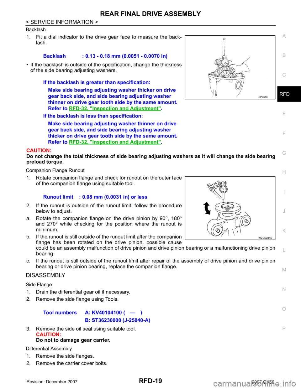
1. Fit a dial indicator to the drive gear face to measure the back-
lash.
• If the backlash is outside of the specification, change the thickness
of the side bearing adjusting washers.
CAUTION:
Do not change the total thickness of side bearing adjusting washers as it will change the side bearing
preload torque.
Companion Flange Runout
1. Rotate companion flange and check for runout on the outer face
of the companion flange using suitable tool.
2. If the runout is outside of the runout limit, follow the procedure
below to adjust.
a. Rotate the companion flange on the drive pinion by 90°, 180°
and 270° while checking for the position where the runout is
minimum.
b. If the runout is still outside of the runout limit after the companion
flange has been rotated on the drive pinion, possible cause
could be an assembly malfunction of drive pinion and drive pinion bearing or a malfunctioning drive pinion
bearing.
c. If the runout is still outside of the runout limit after repair of the assembly of drive pinion and drive pinion
bearing or drive pinion bearing, replace the companion flange.
DISASSEMBLY
Side Flange
1. Drain the differential gear oil if necessary.
2. Remove the side flange using Tools.
3. Remove the side oil seal using suitable tool.
CAUTION:
Do not to damage gear carrier.
Differential Assembly
1. Remove the side flanges.
2. Remove the carrier cover bolts.Backlash : 0.13 - 0.18 mm (0.0051 - 0.0070 in)
If the backlash is greater than specification:
Make side bearing adjusting washer thicker on drive
gear back side, and side bearing adjusting washer
thinner on drive gear tooth side by the same amount.
Refer to RFD-32, "
Inspection and Adjustment".
If the backlash is less than specification:
Make side bearing adjusting washer thinner on drive
gear back side, and side bearing adjusting washer
thicker on drive gear tooth side by the same amount.
Refer to RFD-32, "
Inspection and Adjustment".
SPD513
Runout limit : 0.08 mm (0.0031 in) or less
WDIA0231E
Tool numbers A: KV40104100 ( — )
B: ST36230000 (J-25840-A)
Page 2585 of 3061
RFD-28
< SERVICE INFORMATION >
REAR FINAL DRIVE ASSEMBLY
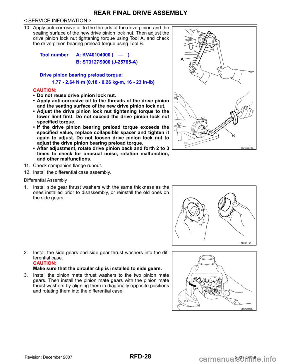
10. Apply anti-corrosive oil to the threads of the drive pinion and the
seating surface of the new drive pinion lock nut. Then adjust the
drive pinion lock nut tightening torque using Tool A, and check
the drive pinion bearing preload torque using Tool B.
CAUTION:
• Do not reuse drive pinion lock nut.
• Apply anti-corrosive oil to the threads of the drive pinion
and the seating surface of the new drive pinion lock nut.
• Adjust the drive pinion lock nut tightening torque to the
lower limit first. Do not exceed the drive pinion lock nut
specified torque.
• If the drive pinion bearing preload torque exceeds the
specified value, replace collapsible spacer and tighten it
again to adjust. Do not loosen drive pinion lock nut to
adjust the drive pinion bearing preload torque.
• After adjustment, rotate drive pinion back and forth 2 to 3
times to check for unusual noise, rotation malfunction,
and other malfunctions.
11. Check companion flange runout.
12. Install the differential case assembly.
Differential Assembly
1. Install side gear thrust washers with the same thickness as the
ones installed prior to disassembly, or reinstall the old ones on
the side gears.
2. Install the side gears and side gear thrust washers into the dif-
ferential case.
CAUTION:
Make sure that the circular clip is installed to side gears.
3. Install the pinion mate thrust washers to the two pinion mate
gears. Then install the pinion mate gears with the pinion mate
thrust washers by aligning them in diagonally opposite positions
and rotating them into the differential case.Tool number A: KV40104000 ( — )
B: ST3127S000 (J-25765-A)
Drive pinion bearing preload torque:
1.77 - 2.64 N·m (0.18 - 0.26 kg-m, 16 - 23 in-lb)
WDIA0379E
SDIA0193J
SDIA2025E
Page 2592 of 3061
RSU-2
< SERVICE INFORMATION >
PRECAUTIONS
SERVICE INFORMATION
PRECAUTIONS
Precaution for Supplemental Restraint System (SRS) "AIR BAG" and "SEAT BELT
PRE-TENSIONER"
INFOID:0000000003532652
The Supplemental Restraint System such as “AIR BAG” and “SEAT BELT PRE-TENSIONER”, used along
with a front seat belt, helps to reduce the risk or severity of injury to the driver and front passenger for certain
types of collision. This system includes seat belt switch inputs and dual stage front air bag modules. The SRS
system uses the seat belt switches to determine the front air bag deployment, and may only deploy one front
air bag, depending on the severity of a collision and whether the front occupants are belted or unbelted.
Information necessary to service the system safely is included in the SRS and SB section of this Service Man-
ual.
WARNING:
• To avoid rendering the SRS inoperative, which could increase the risk of personal injury or death in
the event of a collision which would result in air bag inflation, all maintenance must be performed by
an authorized NISSAN/INFINITI dealer.
• Improper maintenance, including incorrect removal and installation of the SRS, can lead to personal
injury caused by unintentional activation of the system. For removal of Spiral Cable and Air Bag
Module, see the SRS section.
• Do not use electrical test equipment on any circuit related to the SRS unless instructed to in this
Service Manual. SRS wiring harnesses can be identified by yellow and/or orange harnesses or har-
ness connectors.
Precaution for Rear SuspensionINFOID:0000000003532653
• When installing the rubber bushings, the final tightening must be done under unladen condition and with the
tires on level ground. Oil will shorten the life of the rubber bushings, so wipe off any spilled oil immediately.
• Unladen condition means the fuel tank, engine coolant and lubricants are at the full specification. The spare
tire, jack, hand tools, and mats are in their designated positions.
• After installing suspension components, check the wheel alignment.
• Caulking nuts are not reusable. Always use new caulking nuts for installation. New caulking nuts are pre-
oiled, do not apply any additional lubrication.
Page 2612 of 3061
RSU-22
< SERVICE INFORMATION >
REAR SUSPENSION ASSEMBLY
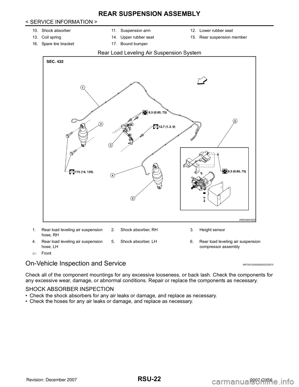
Rear Load Leveling Air Suspension System
On-Vehicle Inspection and ServiceINFOID:0000000003532670
Check all of the component mountings for any excessive looseness, or back lash. Check the components for
any excessive wear, damage, or abnormal conditions. Repair or replace the components as necessary.
SHOCK ABSORBER INSPECTION
• Check the shock absorbers for any air leaks or damage, and replace as necessary.
• Check the hoses for any air leaks or damage, and replace as necessary.
10. Shock absorber 11. Suspension arm 12. Lower rubber seat
13. Coil spring 14. Upper rubber seat 15. Rear suspension member
16. Spare tire bracket 17. Bound bumper
AWEIA0076ZZ
1. Rear load leveling air suspension
hose, RH2. Shock absorber, RH 3. Height sensor
4. Rear load leveling air suspension
hose, LH5. Shock absorber, LH 6. Rear load leveling air suspension
compressor assembly
⇐Front
Page 2618 of 3061

RSU-28
< SERVICE INFORMATION >
REAR SUSPENSION MEMBER
• Do not crimp or stretch the brake hose when repositioning the brake caliper out of the way.
• Do not press brake pedal while the brake caliper is removed.
7. Remove the spare tire.
8. Disconnect the two rear ABS sensor electrical connectors.
9. Remove the two rear drive shafts. Refer to RAX-7, "
Removal and Installation" .
10. Remove the rear final drive. Refer to RFD-14
.
11. Remove the EVAP canister bolt from the top of the rear suspension member.
12. Disconnect the parking brake cables from the brackets on the rear suspension member.
13. Set a suitable jack to support each of the rear lower links and the
coil spring tension.
14. Remove both of the rear lower link outer bolts and lower the jack to remove the rear coil springs.
15. Remove the two bolts to disconnect the seat belt latch anchor
from the rear suspension member.
16. Disconnect both of the connecting rods from the rear stabilizer
bar.
17. Set a suitable jack under the rear suspension member.
18. Remove the six rear suspension member bolts.
19. Slowly lower the jack to remove the rear suspension member,
suspension arm, front and rear lower links and stabilizer bar as
an assembly.
20. If necessary, remove the suspension arm, spare tire bracket,
height sensor, rear load leveling air suspension hoses, stabilizer
bar, knuckle, and front and rear lower links from the rear suspension member.
INSPECTION AFTER REMOVAL
Check the rear suspension member for deformation, cracks, and other damage and replace if necessary.
INSTALLATION
Installation is in the reverse order of removal.
• When raising the rear suspension member assembly, use the
locating pins to align the rear suspension member to the vehicle
body.
LEIA0077E
LEIA0075E
LEIA0083E
Page 2619 of 3061
REAR SUSPENSION MEMBER
RSU-29
< SERVICE INFORMATION >
C
D
F
G
H
I
J
K
L
MA
B
RSU
N
O
P
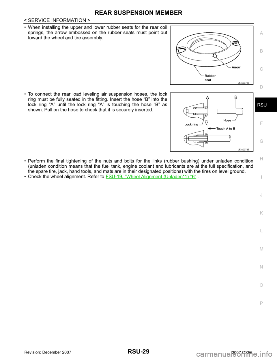
• When installing the upper and lower rubber seats for the rear coil
springs, the arrow embossed on the rubber seats must point out
toward the wheel and tire assembly.
• To connect the rear load leveling air suspension hoses, the lock
ring must be fully seated in the fitting. Insert the hose “B” into the
lock ring “A” until the lock ring “A” is touching the hose “B” as
shown. Pull on the hose to check that it is securely inserted.
• Perform the final tightening of the nuts and bolts for the links (rubber bushing) under unladen condition
(unladen condition means that the fuel tank, engine coolant and lubricants are at the full specification, and
the spare tire, jack, hand tools, and mats are in their designated positions) with the tires on level ground.
• Check the wheel alignment. Refer to FSU-19, "
Wheel Alignment (Unladen*1) *6" .
LEIA0076E
LEIA0078E