2007 INFINITI QX56 battery location
[x] Cancel search: battery locationPage 1982 of 3061
GI-16
< SERVICE INFORMATION >
HOW TO USE THIS MANUAL
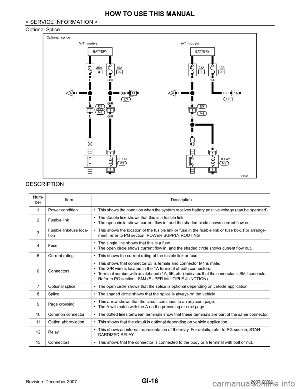
Optional Splice
DESCRIPTION
SGI942
Num-
berItem Description
1 Power condition • This shows the condition when the system receives battery positive voltage (can be operated).
2 Fusible link• The double line shows that this is a fusible link.
• The open circle shows current flow in, and the shaded circle shows current flow out.
3Fusible link/fuse loca-
tion• This shows the location of the fusible link or fuse in the fusible link or fuse box. For arrange-
ment, refer to PG section, POWER SUPPLY ROUTING.
4Fuse• The single line shows that this is a fuse.
• The open circle shows current flow in, and the shaded circle shows current flow out.
5 Current rating • This shows the current rating of the fusible link or fuse.
6 Connectors• This shows that connector E3 is female and connector M1 is male.
• The G/R wire is located in the 1A terminal of both connectors.
• Terminal number with an alphabet (1A, 5B, etc.) indicates that the connector is SMJ connector.
Refer to PG section, SMJ (SUPER MULTIPLE JUNCTION).
7 Optional splice • The open circle shows that the splice is optional depending on vehicle application.
8 Splice • The shaded circle shows that the splice is always on the vehicle.
9 Page crossing• This arrow shows that the circuit continues to an adjacent page.
• The A will match with the A on the preceding or next page.
10 Common connector • The dotted lines between terminals show that these terminals are part of the same connector.
11 Option abbreviation • This shows that the circuit is optional depending on vehicle application.
12 Relay• This shows an internal representation of the relay. For details, refer to PG section, STAN-
DARDIZED RELAY.
13 Connectors • This shows that the connector is connected to the body or a terminal with bolt or nut.
Page 2301 of 3061
LT-94
< SERVICE INFORMATION >
TRAILER TOW
TRAILER TOW
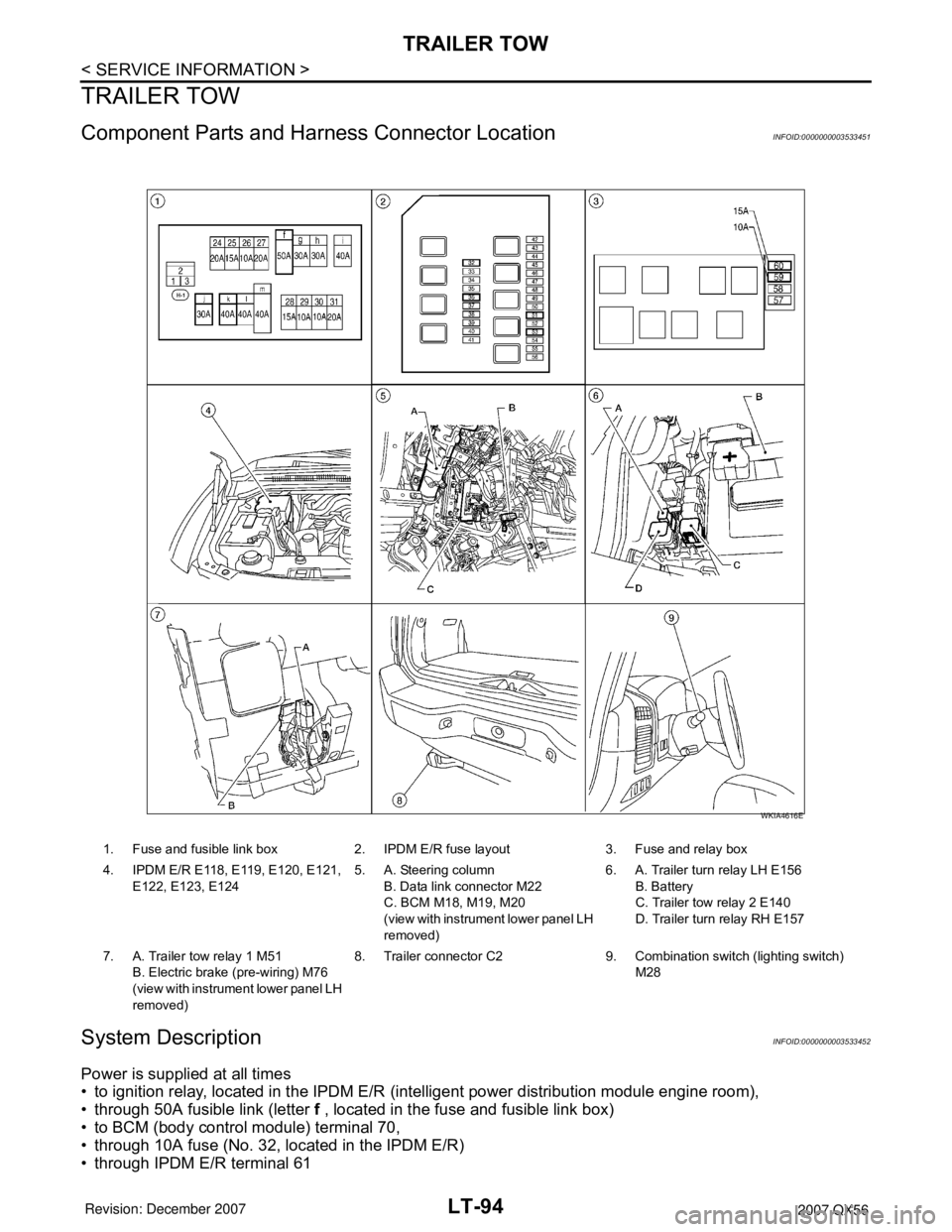
Component Parts and Harness Connector LocationINFOID:0000000003533451
System DescriptionINFOID:0000000003533452
Power is supplied at all times
• to ignition relay, located in the IPDM E/R (intelligent power distribution module engine room),
• through 50A fusible link (letter f , located in the fuse and fusible link box)
• to BCM (body control module) terminal 70,
• through 10A fuse (No. 32, located in the IPDM E/R)
• through IPDM E/R terminal 61
1. Fuse and fusible link box 2. IPDM E/R fuse layout 3. Fuse and relay box
4. IPDM E/R E118, E119, E120, E121,
E122, E123, E1245. A. Steering column
B. Data link connector M22
C. BCM M18, M19, M20
(view with instrument lower panel LH
removed)6. A. Trailer turn relay LH E156
B. Battery
C. Trailer tow relay 2 E140
D. Trailer turn relay RH E157
7. A. Trailer tow relay 1 M51
B. Electric brake (pre-wiring) M76
(view with instrument lower panel LH
removed)8. Trailer connector C2 9. Combination switch (lighting switch)
M28
WKIA4616E
Page 2879 of 3061
TROUBLE DIAGNOSIS FOR SYSTEM
TF-57
< SERVICE INFORMATION >
C
E
F
G
H
I
J
K
L
MA
B
TF
N
O
P
2. Disconnect neutral-4LO switch harness connector.
3. Remove neutral-4LO switch. Refer to TF-22, "
Location of Electrical Parts".
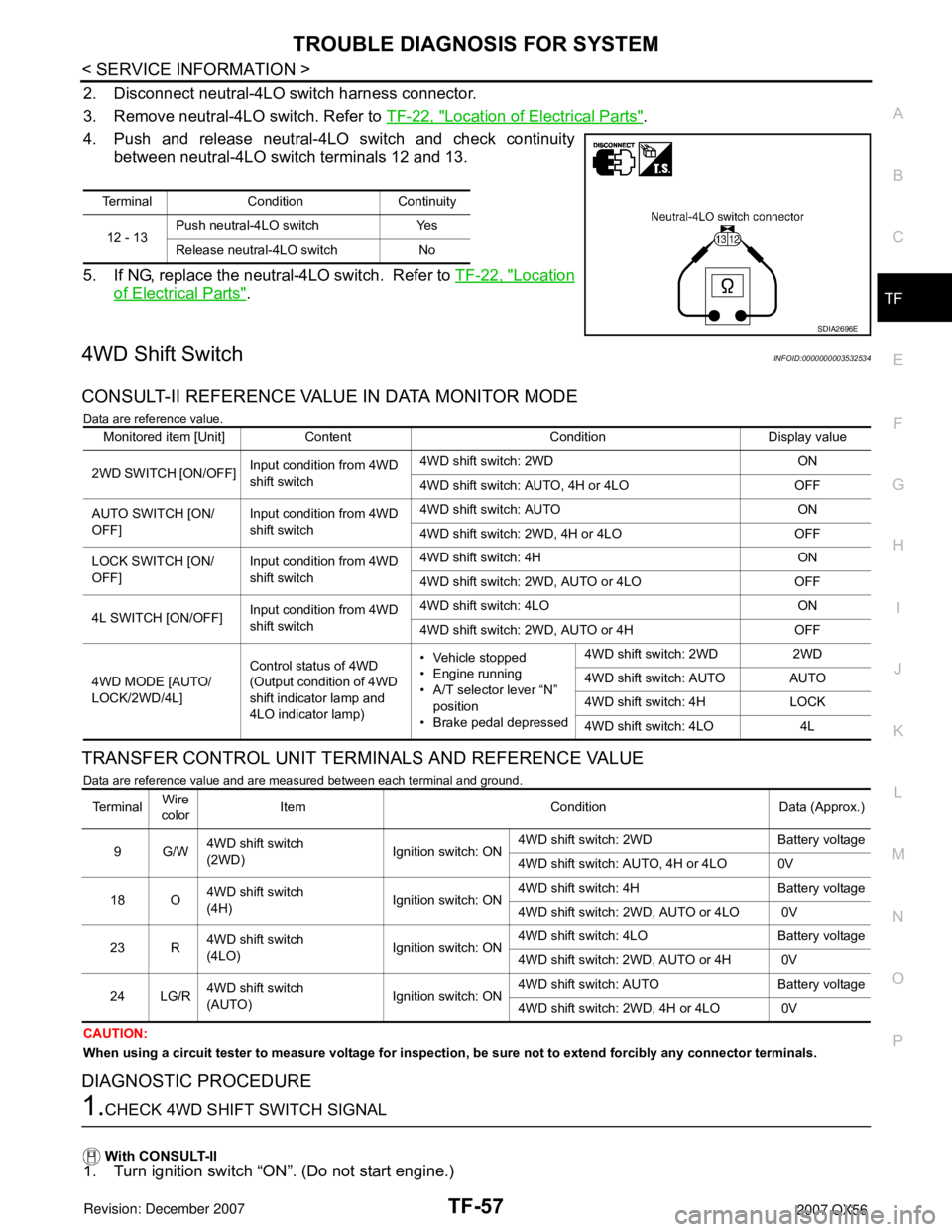
4. Push and release neutral-4LO switch and check continuity
between neutral-4LO switch terminals 12 and 13.
5. If NG, replace the neutral-4LO switch. Refer to TF-22, "
Location
of Electrical Parts".
4WD Shift SwitchINFOID:0000000003532534
CONSULT-II REFERENCE VALUE IN DATA MONITOR MODE
Data are reference value.
TRANSFER CONTROL UNIT TERMINALS AND REFERENCE VALUE
Data are reference value and are measured between each terminal and ground.
CAUTION:
When using a circuit tester to measure voltage for inspection, be sure not to extend forcibly any connector terminals.
DIAGNOSTIC PROCEDURE
1.CHECK 4WD SHIFT SWITCH SIGNAL
With CONSULT-II
1. Turn ignition switch “ON”. (Do not start engine.)
Terminal Condition Continuity
12 - 13Push neutral-4LO switch Yes
Release neutral-4LO switch No
SDIA2696E
Monitored item [Unit] Content Condition Display value
2WD SWITCH [ON/OFF]Input condition from 4WD
shift switch4WD shift switch: 2WD ON
4WD shift switch: AUTO, 4H or 4LO OFF
AUTO SWITCH [ON/
OFF]Input condition from 4WD
shift switch4WD shift switch: AUTO ON
4WD shift switch: 2WD, 4H or 4LO OFF
LOCK SWITCH [ON/
OFF]Input condition from 4WD
shift switch4WD shift switch: 4H ON
4WD shift switch: 2WD, AUTO or 4LO OFF
4L SWITCH [ON/OFF]Input condition from 4WD
shift switch4WD shift switch: 4LO ON
4WD shift switch: 2WD, AUTO or 4H OFF
4WD MODE [AUTO/
LOCK/2WD/4L]Control status of 4WD
(Output condition of 4WD
shift indicator lamp and
4LO indicator lamp)• Vehicle stopped
• Engine running
• A/T selector lever “N”
position
• Brake pedal depressed4WD shift switch: 2WD 2WD
4WD shift switch: AUTO AUTO
4WD shift switch: 4H LOCK
4WD shift switch: 4LO 4L
Te r m i n a lWire
colorItem Condition Data (Approx.)
9G/W4WD shift switch
(2WD)Ignition switch: ON4WD shift switch: 2WD Battery voltage
4WD shift switch: AUTO, 4H or 4LO 0V
18 O4WD shift switch
(4H)Ignition switch: ON4WD shift switch: 4H Battery voltage
4WD shift switch: 2WD, AUTO or 4LO 0V
23 R4WD shift switch
(4LO)Ignition switch: ON4WD shift switch: 4LO Battery voltage
4WD shift switch: 2WD, AUTO or 4H 0V
24 LG/R4WD shift switch
(AUTO)Ignition switch: ON4WD shift switch: AUTO Battery voltage
4WD shift switch: 2WD, 4H or 4LO 0V
Page 2884 of 3061
TF-62
< SERVICE INFORMATION >
TROUBLE DIAGNOSIS FOR SYSTEM
2. Check voltage between transfer control unit harness connector
terminal and ground.
OK or NG
OK >> GO TO 5.
NG >> GO TO 2.
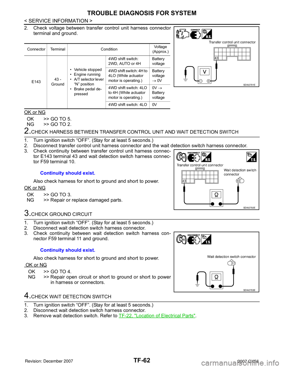
2.CHECK HARNESS BETWEEN TRANSFER CONTROL UNIT AND WAIT DETECTION SWITCH
1. Turn ignition switch “OFF”. (Stay for at least 5 seconds.)
2. Disconnect transfer control unit harness connector and the wait detection switch harness connector.
3. Check continuity between transfer control unit harness connec-
tor E143 terminal 43 and wait detection switch harness connec-
tor F59 terminal 10.
Also check harness for short to ground and short to power.
OK or NG
OK >> GO TO 3.
NG >> Repair or replace damaged parts.
3.CHECK GROUND CIRCUIT
1. Turn ignition switch “OFF”. (Stay for at least 5 seconds.)
2. Disconnect wait detection switch harness connector.
3. Check continuity between wait detection switch harness con-
nector F59 terminal 11 and ground.
Also check harness for short to ground and short to power.
OK or NG
OK >> GO TO 4.
NG >> Repair open circuit or short to ground or short to power
in harness or connectors.
4.CHECK WAIT DETECTION SWITCH
1. Turn ignition switch “OFF”. (Stay for at least 5 seconds.)
2. Disconnect wait detection switch harness connector.
3. Remove wait detection switch. Refer to TF-22, "
Location of Electrical Parts".
Connector Terminal ConditionVoltage
(Approx.)
E14343 -
Ground• Vehicle stopped
• Engine running
• A/T selector lever
“N” position
• Brake pedal de-
pressed4WD shift switch:
2WD, AUTO or 4HBattery
voltage
4WD shift switch: 4H to
4LO (While actuator
motor is operating.)Battery
voltage
→ 0V
4WD shift switch: 4LO
to 4H (While actuator
motor is operating.)0V →
Battery
voltage
4WD shift switch: 4LO 0V
SDIA2701E
Continuity should exist.
SDIA2702E
Continuity should exist.
SDIA2703E
Page 2889 of 3061
TROUBLE DIAGNOSIS FOR SYSTEM
TF-67
< SERVICE INFORMATION >
C
E
F
G
H
I
J
K
L
MA
B
TF
N
O
P
• Harness for short or open between battery, transfer shift high relay harness connector terminal 5
and transfer shift low relay harness connector terminal 5.
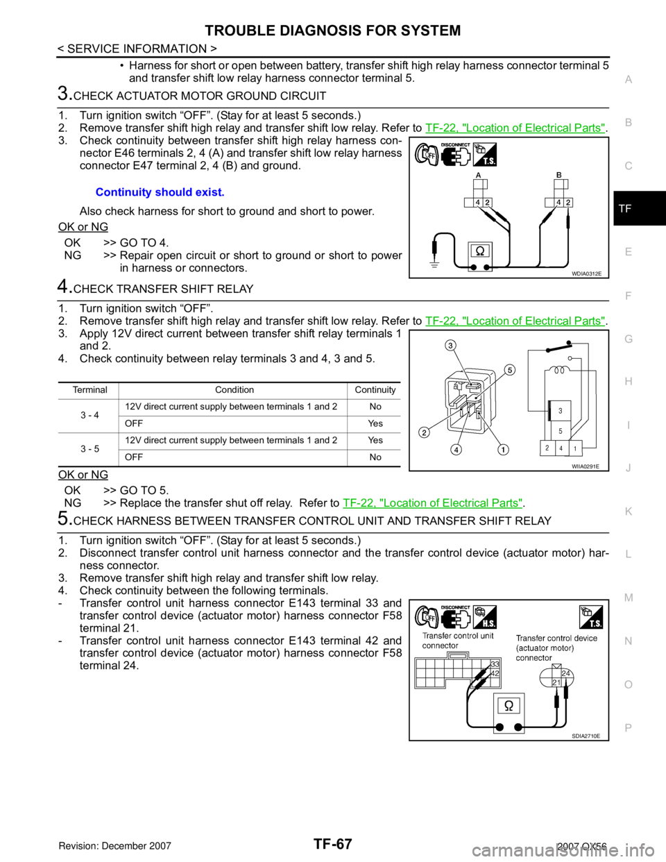
3.CHECK ACTUATOR MOTOR GROUND CIRCUIT
1. Turn ignition switch “OFF”. (Stay for at least 5 seconds.)
2. Remove transfer shift high relay and transfer shift low relay. Refer to TF-22, "
Location of Electrical Parts".
3. Check continuity between transfer shift high relay harness con-
nector E46 terminals 2, 4 (A) and transfer shift low relay harness
connector E47 terminal 2, 4 (B) and ground.
Also check harness for short to ground and short to power.
OK or NG
OK >> GO TO 4.
NG >> Repair open circuit or short to ground or short to power
in harness or connectors.
4.CHECK TRANSFER SHIFT RELAY
1. Turn ignition switch “OFF”.
2. Remove transfer shift high relay and transfer shift low relay. Refer to TF-22, "
Location of Electrical Parts".
3. Apply 12V direct current between transfer shift relay terminals 1
and 2.
4. Check continuity between relay terminals 3 and 4, 3 and 5.
OK or NG
OK >> GO TO 5.
NG >> Replace the transfer shut off relay. Refer to TF-22, "
Location of Electrical Parts".
5.CHECK HARNESS BETWEEN TRANSFER CONTROL UNIT AND TRANSFER SHIFT RELAY
1. Turn ignition switch “OFF”. (Stay for at least 5 seconds.)
2. Disconnect transfer control unit harness connector and the transfer control device (actuator motor) har-
ness connector.
3. Remove transfer shift high relay and transfer shift low relay.
4. Check continuity between the following terminals.
- Transfer control unit harness connector E143 terminal 33 and
transfer control device (actuator motor) harness connector F58
terminal 21.
- Transfer control unit harness connector E143 terminal 42 and
transfer control device (actuator motor) harness connector F58
terminal 24.Continuity should exist.
WDIA0312E
Terminal Condition Continuity
3 - 412V direct current supply between terminals 1 and 2 No
OFF Yes
3 - 512V direct current supply between terminals 1 and 2 Yes
OFF No
WIIA0291E
SDIA2710E
Page 2891 of 3061
TROUBLE DIAGNOSIS FOR SYSTEM
TF-69
< SERVICE INFORMATION >
C
E
F
G
H
I
J
K
L
MA
B
TF
N
O
P
Perform the self-diagnosis, after driving a vehicle for a while.
OK or NG
OK >> Inspection End.
NG >> Replace transfer control unit. Refer to TF-115, "
Removal and Installation".
COMPONENT INSPECTION
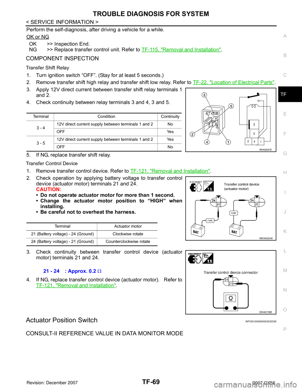
Transfer Shift Relay
1. Turn ignition switch “OFF”. (Stay for at least 5 seconds.)
2. Remove transfer shift high relay and transfer shift low relay. Refer to TF-22, "
Location of Electrical Parts".
3. Apply 12V direct current between transfer shift relay terminals 1
and 2.
4. Check continuity between relay terminals 3 and 4, 3 and 5.
5. If NG, replace transfer shift relay.
Transfer Control Device
1. Remove transfer control device. Refer to TF-121, "Removal and Installation".
2. Check operation by applying battery voltage to transfer control
device (actuator motor) terminals 21 and 24.
CAUTION:
• Do not operate actuator motor for more than 1 second.
• Change the actuator motor position to “HIGH” when
installing.
• Be careful not to overheat the harness.
3. Check continuity between transfer control device (actuator
motor) terminals 21 and 24.
4. If NG, replace transfer control device (actuator motor). Refer to
TF-121, "
Removal and Installation".
Actuator Position SwitchINFOID:0000000003532538
CONSULT-II REFERENCE VALUE IN DATA MONITOR MODE
Terminal Condition Continuity
3 - 412V direct current supply between terminals 1 and 2 No
OFF Yes
3 - 512V direct current supply between terminals 1 and 2 Yes
OFF No
WIIA0291E
Terminal Actuator motor
21 (Battery voltage) - 24 (Ground) Clockwise rotate
24 (Battery voltage) - 21 (Ground) Counterclockwise rotate
WDIA0224E
21 - 24 : Approx. 0.2 Ω
SDIA2726E
Page 2896 of 3061
TF-74
< SERVICE INFORMATION >
TROUBLE DIAGNOSIS FOR SYSTEM
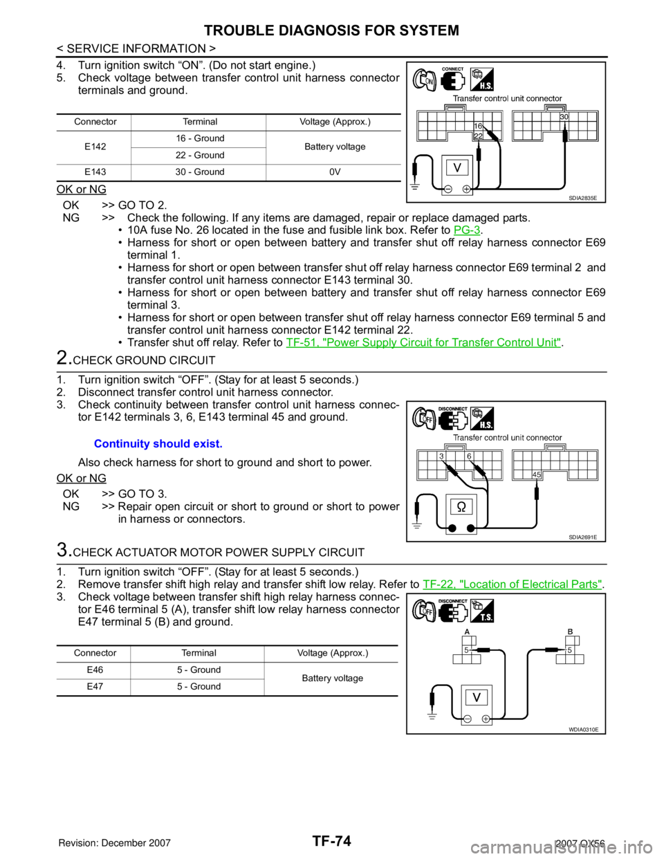
4. Turn ignition switch “ON”. (Do not start engine.)
5. Check voltage between transfer control unit harness connector
terminals and ground.
OK or NG
OK >> GO TO 2.
NG >> Check the following. If any items are damaged, repair or replace damaged parts.
• 10A fuse No. 26 located in the fuse and fusible link box. Refer to PG-3
.
• Harness for short or open between battery and transfer shut off relay harness connector E69
terminal 1.
• Harness for short or open between transfer shut off relay harness connector E69 terminal 2 and
transfer control unit harness connector E143 terminal 30.
• Harness for short or open between battery and transfer shut off relay harness connector E69
terminal 3.
• Harness for short or open between transfer shut off relay harness connector E69 terminal 5 and
transfer control unit harness connector E142 terminal 22.
• Transfer shut off relay. Refer to TF-51, "
Power Supply Circuit for Transfer Control Unit".
2.CHECK GROUND CIRCUIT
1. Turn ignition switch “OFF”. (Stay for at least 5 seconds.)
2. Disconnect transfer control unit harness connector.
3. Check continuity between transfer control unit harness connec-
tor E142 terminals 3, 6, E143 terminal 45 and ground.
Also check harness for short to ground and short to power.
OK or NG
OK >> GO TO 3.
NG >> Repair open circuit or short to ground or short to power
in harness or connectors.
3.CHECK ACTUATOR MOTOR POWER SUPPLY CIRCUIT
1. Turn ignition switch “OFF”. (Stay for at least 5 seconds.)
2. Remove transfer shift high relay and transfer shift low relay. Refer to TF-22, "
Location of Electrical Parts".
3. Check voltage between transfer shift high relay harness connec-
tor E46 terminal 5 (A), transfer shift low relay harness connector
E47 terminal 5 (B) and ground.
Connector Terminal Voltage (Approx.)
E14216 - Ground
Battery voltage
22 - Ground
E143 30 - Ground 0V
SDIA2835E
Continuity should exist.
SDIA2691E
Connector Terminal Voltage (Approx.)
E46 5 - Ground
Battery voltage
E47 5 - Ground
WDIA0310E
Page 2897 of 3061
TROUBLE DIAGNOSIS FOR SYSTEM
TF-75
< SERVICE INFORMATION >
C
E
F
G
H
I
J
K
L
MA
B
TF
N
O
P
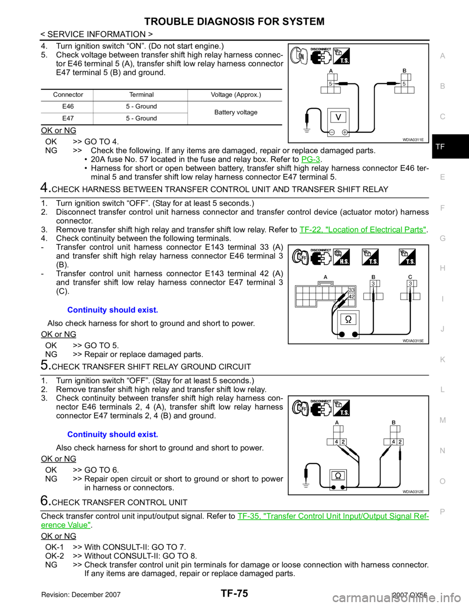
4. Turn ignition switch “ON”. (Do not start engine.)
5. Check voltage between transfer shift high relay harness connec-
tor E46 terminal 5 (A), transfer shift low relay harness connector
E47 terminal 5 (B) and ground.
OK or NG
OK >> GO TO 4.
NG >> Check the following. If any items are damaged, repair or replace damaged parts.
• 20A fuse No. 57 located in the fuse and relay box. Refer to PG-3
.
• Harness for short or open between battery, transfer shift high relay harness connector E46 ter-
minal 5 and transfer shift low relay harness connector E47 terminal 5.
4.CHECK HARNESS BETWEEN TRANSFER CONTROL UNIT AND TRANSFER SHIFT RELAY
1. Turn ignition switch “OFF”. (Stay for at least 5 seconds.)
2. Disconnect transfer control unit harness connector and transfer control device (actuator motor) harness
connector.
3. Remove transfer shift high relay and transfer shift low relay. Refer to TF-22, "
Location of Electrical Parts".
4. Check continuity between the following terminals.
- Transfer control unit harness connector E143 terminal 33 (A)
and transfer shift high relay harness connector E46 terminal 3
(B).
- Transfer control unit harness connector E143 terminal 42 (A)
and transfer shift low relay harness connector E47 terminal 3
(C).
Also check harness for short to ground and short to power.
OK or NG
OK >> GO TO 5.
NG >> Repair or replace damaged parts.
5.CHECK TRANSFER SHIFT RELAY GROUND CIRCUIT
1. Turn ignition switch “OFF”. (Stay for at least 5 seconds.)
2. Remove transfer shift high relay and transfer shift low relay.
3. Check continuity between transfer shift high relay harness con-
nector E46 terminals 2, 4 (A), transfer shift low relay harness
connector E47 terminals 2, 4 (B) and ground.
Also check harness for short to ground and short to power.
OK or NG
OK >> GO TO 6.
NG >> Repair open circuit or short to ground or short to power
in harness or connectors.
6.CHECK TRANSFER CONTROL UNIT
Check transfer control unit input/output signal. Refer to TF-35, "
Transfer Control Unit Input/Output Signal Ref-
erence Value".
OK or NG
OK-1 >> With CONSULT-II: GO TO 7.
OK-2 >> Without CONSULT-II: GO TO 8.
NG >> Check transfer control unit pin terminals for damage or loose connection with harness connector.
If any items are damaged, repair or replace damaged parts.
Connector Terminal Voltage (Approx.)
E46 5 - Ground
Battery voltage
E47 5 - Ground
WDIA0311E
Continuity should exist.
WDIA0315E
Continuity should exist.
WDIA0312E