2007 INFINITI QX56 brake sensor
[x] Cancel search: brake sensorPage 2112 of 3061

IDX-8
ALPHABETICAL INDEX
Three way catalyst ............................................ EM-21
Three way catalyst function (Bank 1) ............... EC-376
Three way catalyst function (Bank 2) ............... EC-376
Three way catalyst precautions ............................ GI-5
Throttle control motor ....................................... EC-601
Throttle control motor relay .............................. EC-589
Throttle position sensor (TPS) .. EC-224, EC-343, EC-
514, EC-516, EC-621
Throttle valve closed position learning ............... EC-80
Tie-rod ............................................................... PS-15
Timing chain ..................................................... EM-37
Tire rotation ....................................................... MA-28
Tire size .............................................................. GI-51
Torque converter installation AT-239, AT-240, AT-243,
AT-244
Torque convertor clutch solenoid valve ... AT-114, AT-
116
Tow truck towing ................................................. GI-44
Towing point ....................................................... GI-45
TPS1 - Wiring diagram .................................... EC-345
TPS2 - Wiring diagram .................................... EC-226
TPS3 - Wiring diagram .................................... EC-623
Traction control system - Wiring diagram ....... BRC-16
Transfer control device ............. TF-75, TF-79, TF-138
Transfer control unit inspection table ................. TF-35
Transfer dropping resistor .................................. TF-89
Transfer fluid temperature sensor TF-103, TF-154, TF-
167
Transfer motor .................................... TF-101, TF-142
Transfer motor relay ........................................ TF-101
Transfer oil replacement ................................... MA-24
Transfer serial number ........................................ GI-50
Transmission serial number ................................ GI-50
Tread-FR&RR (Dimensions) ............................... GI-51
Trim ..................................................................... EI-35
TRNSCV - Wiring diagram .................. BL-130, BL-146
Trouble diagnoses .............................................. GI-11
Turbine revolution sensor ................................ AT-105
TURN - Wiring diagram ...................................... LT-67
Turn signal lamp ................................................. LT-63
Two trip detection logic ...................................... EC-49
Two-pole lift ........................................................ GI-43
V
Vacuum hose (brake system) ............................ BR-20
Vacuum hose drawing (Engine control) ........... EC-106
Valve clearance ................................................ EM-55
Valve guide ....................................................... EM-69
Vanity mirror lamp ............................................. LT-110
VDC (vehicle dynamics control) ........................ BRC-7
VDC -Wiring diagram ...................................... BRC-16
Vehicle identification number .............................. GI-49
Vehicle recovery (freeing a stuck vehicle) .......... GI-45
Vehicle security (theft warning) system ............. BL-67
Vehicle speed sensor (VSS) ............................ EC-464
VEHSEC - Wiring diagram ................................. BL-71
VENT/V - Wiring diagram .................. EC-412, EC-419
VIN registration .................................................. EC-79
Viscosity number (SAE) .................................... MA-12
VSS A/T - Wiring diagram .................. AT-107, AT-109
W
W/ANT - Wiring diagram .................................... AV-59
Wait detection switch ......................................... TF-68
WARN - Wiring diagram ...................................... DI-29
Warning chime .................................................... DI-38
Warning lamps .................................................... DI-28
Washer, front ..................................................... WW-4
Washer, rear .................................................... WW-29
Water pump ...................................................... CO-19
Water temperature gauge ..................................... DI-5
Wheel alignment (front) ..................................... FSU-6
Wheel alignment (rear) ................................... RSU-25
Wheel bearing (front) ........................................ FAX-5
Wheel bearing (rear) ......................................... RAX-5
Wheel hub (rear) ............................................... RAX-5
Wheel size .......................................................... GI-51
Wheelbase (Dimensions) .................................... GI-51
Width (Dimensions) ............................................. GI-51
WINDOW - Wiring diagram .............................. GW-22
Window, door ...................................... GW-62, GW-65
Windshield ....................................................... GW-11
WIP/R - Wiring diagram ................................... WW-33
WIPER - Wiring diagram .................................... WW-8
Wiper, front ........................................................ WW-4
Wiper, rear ....................................................... WW-29
Wiring Diagram (Cell code) list ......................... PG-62
Wiring diagrams .................................................. GI-15
WT-T/WARN - Wiring diagram .......................... WT-11
Page 2177 of 3061
![INFINITI QX56 2007 Factory Service Manual LAN-46
< SERVICE INFORMATION >[CAN]
TROUBLE DIAGNOSIS
NOTE:
CAN data of the air bag diagnosis sensor unit is not used by usual service work, thus it is omitted.
TYPE 3/TYPE 4
NOTE:
Refer to LAN-37, " INFINITI QX56 2007 Factory Service Manual LAN-46
< SERVICE INFORMATION >[CAN]
TROUBLE DIAGNOSIS
NOTE:
CAN data of the air bag diagnosis sensor unit is not used by usual service work, thus it is omitted.
TYPE 3/TYPE 4
NOTE:
Refer to LAN-37, "](/manual-img/42/57029/w960_57029-2176.png)
LAN-46
< SERVICE INFORMATION >[CAN]
TROUBLE DIAGNOSIS
NOTE:
CAN data of the air bag diagnosis sensor unit is not used by usual service work, thus it is omitted.
TYPE 3/TYPE 4
NOTE:
Refer to LAN-37, "
Abbreviation List" for the abbreviations of the connecting units.
T: Transmit R: Receive
A/C switch/indicator signalTR
RT
1st position switch signal R T
4th position switch signal R T
Distance to empty signal R T
Fuel level low warning signal R T
Fuel level sensor signal R T
Parking brake switch signal R T
Stop lamp switch signal R T
Tow mode switch signal R T
Vehicle speed signalRR T
RRR RRR T
Steering angle sensor signalTR
ABS malfunction signal R T
ABS warning lamp signalRT
Brake pressure sensor signal R T
Brake warning lamp signalRT
SLIP indicator lamp signalRT
TCS malfunction signal R T
VDC malfunction signal R T
VDC OFF indicator lamp signal R R T
VDC operation signal R T
Front wiper stop position signal R T
High beam status signal RT
Hood switch signal R T
Low beam status signal RT
Rear window defogger control signal R R TSignal name/Connecting unit
ECM
TCM
LASER
ICC
ADP
BCM
DISP
HVAC
M&A
STRG
ABS
IPDM-E
Signal name/Connecting unitECM
TCM
LASER
ICC
ADP
BCM
DISP
HVAC
M&A
STRG
4WD
ABS
IPDM-E
A/C compressor request signal TR
Accelerator pedal position signal T R R R R
ASCD CRUISE lamp signal T R
ASCD OD cancel request signal T R
ASCD operation signal T R
ASCD SET lamp signal T R
Battery voltage signal T R
Closed throttle position signal T R R
Page 2179 of 3061
![INFINITI QX56 2007 Factory Service Manual LAN-48
< SERVICE INFORMATION >[CAN]
TROUBLE DIAGNOSIS
NOTE:
CAN data of the air bag diagnosis sensor unit is not used by usual service work, thus it is omitted.
Tire pressure signal T R R
Turn indica INFINITI QX56 2007 Factory Service Manual LAN-48
< SERVICE INFORMATION >[CAN]
TROUBLE DIAGNOSIS
NOTE:
CAN data of the air bag diagnosis sensor unit is not used by usual service work, thus it is omitted.
Tire pressure signal T R R
Turn indica](/manual-img/42/57029/w960_57029-2178.png)
LAN-48
< SERVICE INFORMATION >[CAN]
TROUBLE DIAGNOSIS
NOTE:
CAN data of the air bag diagnosis sensor unit is not used by usual service work, thus it is omitted.
Tire pressure signal T R R
Turn indicator signal T R
A/C switch/indicator signalTR
RT
1st position switch signal R T
4th position switch signal R T
Distance to empty signal R T
Fuel level low warning signal R T
Fuel level sensor signal R T
Parking brake switch signal R T
Stop lamp switch signal R T
Tow mode switch signal R T
Vehicle speed signalRR R T
RRR RRR T
Steering angle sensor signalTR
ABS malfunction signal R T
ABS warning lamp signalRT
Brake pressure sensor signal R T
Brake warning lamp signalRT
SLIP indicator lamp signalRT
TCS malfunction signal R T
VDC malfunction signal R T
VDC OFF indicator lamp signal R R T
VDC operation signal R T
Front wiper stop position signal R T
High beam status signal RT
Hood switch signal R T
Low beam status signal RT
Rear window defogger control signal R R TSignal name/Connecting unit
ECM
TCM
LASER
ICC
ADP
BCM
DISP
HVAC
M&A
STRG
4WD
ABS
IPDM-E
Page 2399 of 3061

PB-6
< SERVICE INFORMATION >
PARKING BRAKE SHOE
PARKING BRAKE SHOE
Removal and InstallationINFOID:0000000003532758
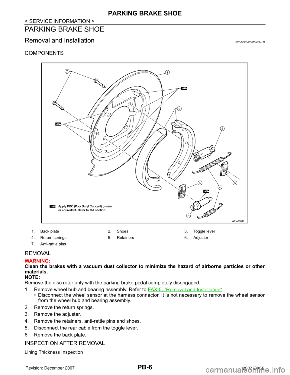
COMPONENTS
REMOVAL
WARNING:
Clean the brakes with a vacuum dust collector to minimize the hazard of airborne particles or other
materials.
NOTE:
Remove the disc rotor only with the parking brake pedal completely disengaged.
1. Remove wheel hub and bearing assembly. Refer to FA X - 5 , "
Removal and Installation" .
• Disconnect the wheel sensor at the harness connector. It is not necessary to remove the wheel sensor
from the wheel hub and bearing assembly.
2. Remove the return springs.
3. Remove the adjuster.
4. Remove the retainers, anti-rattle pins and shoes.
5. Disconnect the rear cable from the toggle lever.
6. Remove the back plate.
INSPECTION AFTER REMOVAL
Lining Thickness Inspection
1. Back plate 2. Shoes 3. Toggle lever
4. Return springs 5. Retainers 6. Adjuster
7. Anti-rattle pins
WFIA0164E
Page 2462 of 3061

PG-60
< SERVICE INFORMATION >
HARNESS
Code Section Wiring Diagram Name
A/C,A ATC Auto Air Conditioner
A/SUSP RSU Rear Air Suspension
AF1B1 EC Air Fuel Ratio (A/F) Sensor 1 (Bank 1)
AF1B2 EC Air Fuel Ratio (A/F) Sensor 1 (Bank 2)
AF1HB1 EC Air Fuel Ratio (A/F) Sensor 1 (Bank 1)
AF1HB2 EC Air Fuel Ratio (A/F) Sensor 1 (Bank 2)
APPS1 EC Accelerator Pedal Position Sensor
APPS2 EC Accelerator Pedal Position Sensor
APPS3 EC Accelerator Pedal Position Sensor
ASC/BS EC ASCD Brake Switch
ASC/SW EC ASCD Steering Switch
ASCBOF EC ASCD Brake Switch
ASCIND EC ASCD Indicator
A/T AT A/T Assembly
AT/IND DI A/T Indicator Lamp
AUDIO AV Audio
AUT/DP SE Automatic Drive Positioner
AUTO/L LT Auto Light Control
B/CLOS BL Back Door Auto Closure System
BACK/L LT Back-up Lamp
BRK/SW EC Brake Switch
CAN EC CAN Communication Line
CAN LAN CAN System
CHARGE SC Charging System
CHIME DI Warning Chime
CLOCK DI Clock
COOL/F EC Cooling Fan Control
COMBSW LT Combination Switch
COMM AV Audio Visual Communication System
COMPAS DI Compass and Thermometer
D/LOCK BL Power Door Lock
DEF GW Rear Window Defogger
DTRL LT Headlamp - With Daytime Light System
DVD AV DVD Entertainment System
ECM/PW EC ECM Power Supply for Back-Up
ECTS EC Engine Coolant Temperature Sensor
ETC1 EC Electric Throttle Control Function
ETC2 EC Throttle Control Motor Relay
ETC3 EC Throttle Control Motor
F/FOG LT Front Fog Lamp
F/PUMP EC Fuel Pump
FTTS EC Fuel Tank Temperature Sensor
FUELB1 EC Fuel Injection System Bank 1
FUELB2 EC Fuel Injection System Bank 2
H/AIM LT Headlamp Aiming Control
H/PHON AV Hands Free Telephone
H/LAMP LT Headlamp
HORN WW Horn
HSEAT SE Heated Seat
ICC ACS Intelligent Cruise Control
ICCBOF EC ICC Brake Switch
Page 2463 of 3061

HARNESS
PG-61
< SERVICE INFORMATION >
C
D
E
F
G
H
I
J
L
MA
B
PG
N
O
P
ICC/BS EC ICC Steering Switch
ICC/SW EC ICC Brake Switch
I/MIRR GW Inside Mirror (Auto Anti-Dazzling Mirror)
IATS EC Intake Air Temperature Sensor
IGNSYS EC Ignition System
ILL LT Illumination
INJECT EC Injector
INT/L LT Room/Map, Vanity, Cargo, Personal, Foot, Step, and Puddle Lamps
KEYLES BL Remote Keyless Entry System
KS EC Knock Sensor
MAFS EC Mass Air Flow Sensor
MAIN EC Main Power Supply and Ground Circuit
METER DI Speedometer, Tachometer, Temp. and Fuel Gauges
MIL/DL EC Malfunction Indicator Lamp
MIRROR GW Door Mirror
NATS BL Nissan Anti-Theft System
NAVI AV Navigation System
O2H2B1 EC Rear Heated Oxygen Sensor 2 Heater Bank 1
O2H2B2 EC Rear Heated Oxygen Sensor 2 Heater Bank 2
O2S2B1 EC Heated Oxygen Sensor 2 Bank 1
O2S2B2 EC Heated Oxygen Sensor 2 Bank 2
P/SCKT WW Power Socket
PGC/V EC EVAP Canister Purge Volume Control Solenoid Valve
PHASE EC Camshaft Position Sensor (PHASE) (Bank 1)
PNP/SW EC Park/Neutral Position Switch
POS EC Crankshaft Position Sensor (POS)
POWER PG Power Supply Routing
PRE/SE EC EVAP Control System Pressure Sensor
PS/SEN EC Power Steering Pressure Sensor
R/VIEW DI Rear View Monitor
RP/SEN EC Refrigerant Pressure Sensor
SEN/PW EC Sensor Power Supply
SHIFT AT A/T Shift Lock System
SONAR DI Rear Sonar System
SROOF RF Sunroof
SRS SRS Supplemental Restraint System
START SC Starting System
STOP/L LT Stop Lamp
T/TOW LT Trailer Tow
T/WARN WT Low Tire Pressure Warning System
TAIL/L LT Parking, License and Tail Lamps
T/F TF Transfer Case
TPS1 EC Throttle Position Sensor
TPS2 EC Throttle Position Sensor
TPS3 EC Throttle Position Sensor
TRNSCV BL HOMELINK® Universal Transceiver
TURN LT Turn Signal and Hazard Warning Lamps
VDC BRC Vehicle Dynamic Control System
VEHSEC BL Vehicle security (theft warning) system
VENT/V EC EVAP Canister Vent Control Valve
W/ANT AV Audio Antenna
WARN DI Warning Lamps
Page 2523 of 3061

WHEEL HUB
RAX-5
< SERVICE INFORMATION >
C
E
F
G
H
I
J
K
L
MA
B
RAX
N
O
P
WHEEL HUB
On-Vehicle Inspection and ServiceINFOID:0000000003532624
Inspect the components for any looseness or back lash. Inspect each component for any excessive wear or
damage. Replace any components as necessary.
WHEEL BEARING INSPECTION
• Move the wheel hub and bearing assembly in the axial direction by hand to check the axial end play. Check
that the axial end play is with specification. Replace the wheel hub and bearing assembly as necessary.
• Rotate the wheel hub and bearing assembly to check that there are no unusual noises or other abnormal
conditions. Replace the wheel hub and bearing assembly as necessary.
Removal and InstallationINFOID:0000000003532625
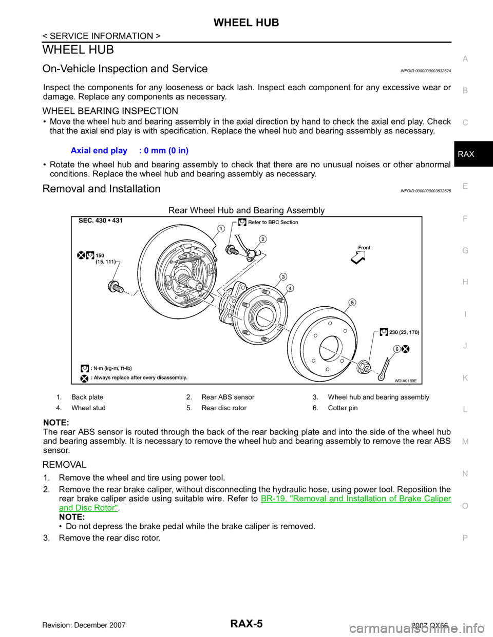
Rear Wheel Hub and Bearing Assembly
NOTE:
The rear ABS sensor is routed through the back of the rear backing plate and into the side of the wheel hub
and bearing assembly. It is necessary to remove the wheel hub and bearing assembly to remove the rear ABS
sensor.
REMOVAL
1. Remove the wheel and tire using power tool.
2. Remove the rear brake caliper, without disconnecting the hydraulic hose, using power tool. Reposition the
rear brake caliper aside using suitable wire. Refer to BR-19, "
Removal and Installation of Brake Caliper
and Disc Rotor".
NOTE:
• Do not depress the brake pedal while the brake caliper is removed.
3. Remove the rear disc rotor.Axial end play : 0 mm (0 in)
WDIA0189E
1. Back plate 2. Rear ABS sensor 3. Wheel hub and bearing assembly
4. Wheel stud 5. Rear disc rotor 6. Cotter pin
Page 2524 of 3061

RAX-6
< SERVICE INFORMATION >
WHEEL HUB
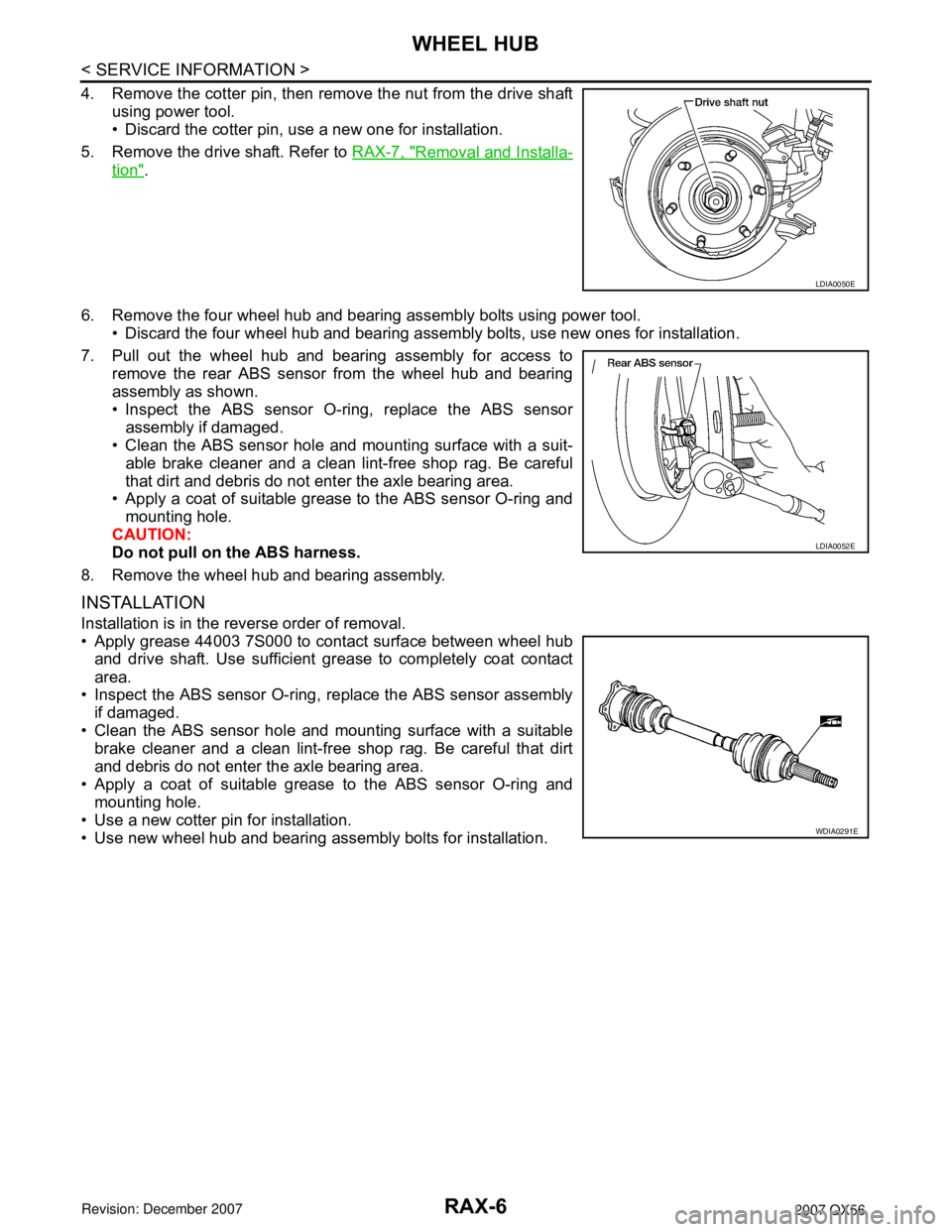
4. Remove the cotter pin, then remove the nut from the drive shaft
using power tool.
• Discard the cotter pin, use a new one for installation.
5. Remove the drive shaft. Refer to RAX-7, "
Removal and Installa-
tion".
6. Remove the four wheel hub and bearing assembly bolts using power tool.
• Discard the four wheel hub and bearing assembly bolts, use new ones for installation.
7. Pull out the wheel hub and bearing assembly for access to
remove the rear ABS sensor from the wheel hub and bearing
assembly as shown.
• Inspect the ABS sensor O-ring, replace the ABS sensor
assembly if damaged.
• Clean the ABS sensor hole and mounting surface with a suit-
able brake cleaner and a clean lint-free shop rag. Be careful
that dirt and debris do not enter the axle bearing area.
• Apply a coat of suitable grease to the ABS sensor O-ring and
mounting hole.
CAUTION:
Do not pull on the ABS harness.
8. Remove the wheel hub and bearing assembly.
INSTALLATION
Installation is in the reverse order of removal.
• Apply grease 44003 7S000 to contact surface between wheel hub
and drive shaft. Use sufficient grease to completely coat contact
area.
• Inspect the ABS sensor O-ring, replace the ABS sensor assembly
if damaged.
• Clean the ABS sensor hole and mounting surface with a suitable
brake cleaner and a clean lint-free shop rag. Be careful that dirt
and debris do not enter the axle bearing area.
• Apply a coat of suitable grease to the ABS sensor O-ring and
mounting hole.
• Use a new cotter pin for installation.
• Use new wheel hub and bearing assembly bolts for installation.
LDIA0050E
LDIA0052E
WDIA0291E