Page 1014 of 3061

PRECAUTIONDI-3
< SERVICE INFORMATION >
C
DE
F
G H
I
J
L
M A
B
DI
N
O P
SERVICE INFORMATION
PRECAUTION
Precaution for Supplemental Restraint System (SRS) "AIR BAG" and "SEAT BELT
PRE-TENSIONER"
INFOID:0000000003533477
The Supplemental Restraint System such as “A IR BAG” and “SEAT BELT PRE-TENSIONER”, used along
with a front seat belt, helps to reduce the risk or severi ty of injury to the driver and front passenger for certain
types of collision. This system includes seat belt switch inputs and dual stage front air bag modules. The SRS
system uses the seat belt switches to determine the front air bag deployment, and may only deploy one front
air bag, depending on the severity of a collision and w hether the front occupants are belted or unbelted.
Information necessary to service the system safely is included in the SRS and SB section of this Service Man-
ual.
WARNING:
• To avoid rendering the SRS inoper ative, which could increase the risk of personal injury or death in
the event of a collision which would result in air bag inflation, all maintenance must be performed by
an authorized NISSAN/INFINITI dealer.
• Improper maintenance, including in correct removal and installation of the SRS, can lead to personal
injury caused by unintentional act ivation of the system. For removal of Spiral Cable and Air Bag
Module, see the SRS section.
• Do not use electrical test equipm ent on any circuit related to the SRS unless instructed to in this
Service Manual. SRS wiring harnesses can be identi fied by yellow and/or orange harnesses or har-
ness connectors.
Page 1015 of 3061
DI-4
< SERVICE INFORMATION >
PREPARATION
PREPARATION
Commercial Service ToolINFOID:0000000003533478
Tool nameDescription
Power tool Loosening bolts and nuts.
PBIC0191E
Page 1016 of 3061

COMBINATION METERSDI-5
< SERVICE INFORMATION >
C
DE
F
G H
I
J
L
M A
B
DI
N
O P
COMBINATION METERS
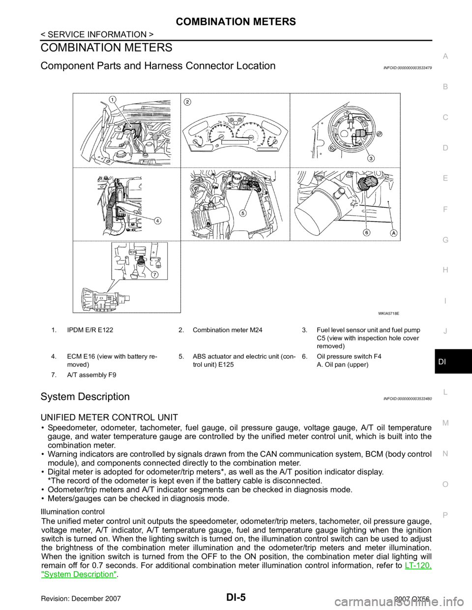
Component Parts and Har ness Connector LocationINFOID:0000000003533479
System DescriptionINFOID:0000000003533480
UNIFIED METER CONTROL UNIT
• Speedometer, odometer, tachometer, fuel gauge, oil pressure gauge, voltage gauge, A/T oil temperature
gauge, and water temperature gauge are controlled by the unified meter control unit, which is built into the
combination meter.
• Warning indicators are controlled by signals drawn fr om the CAN communication system, BCM (body control
module), and components connected directly to the combination meter.
• Digital meter is adopted for odometer/trip meters*, as well as the A/T position indicator display. *The record of the odometer is kept ev en if the battery cable is disconnected.
• Odometer/trip meters and A/T indicator segments can be checked in diagnosis mode.
• Meters/gauges can be checked in diagnosis mode.
Illumination control
The unified meter control unit outputs the speedometer, odometer/trip meters, tachometer, oil pressure gauge,
voltage meter, A/T indicator, A/T temperature gauge, fuel and temperature gauge lighting when the ignition
switch is turned on. When the lighting switch is turned on, the illumination control switch can be used to adjust
the brightness of the combination meter illuminati on and the odometer/trip meters and meter illumination.
When the ignition switch is turned from the OFF to the ON position, the combination meter dial lighting will
remain off for 0.7 seconds. For additional combination meter illumination control information, refer to LT-120,
"System Description".
1. IPDM E/R E122 2. Combination meter M24 3. Fuel level sensor unit and fuel pump
C5 (view with inspection hole cover
removed)
4. ECM E16 (view with battery re- moved) 5. ABS actuator and electric unit (con-
trol unit) E125 6. Oil pressure switch F4
A. Oil pan (upper)
7. A/T assembly F9
WKIA5718E
Page 1017 of 3061
![INFINITI QX56 2007 Factory Service Manual
DI-6
< SERVICE INFORMATION >
COMBINATION METERS
POWER SUPPLY AND GROUND CIRCUIT
Power is supplied at all times
• through 10A fuse [No.19, located in the fuse block (J/B)]
• to combination meter t INFINITI QX56 2007 Factory Service Manual
DI-6
< SERVICE INFORMATION >
COMBINATION METERS
POWER SUPPLY AND GROUND CIRCUIT
Power is supplied at all times
• through 10A fuse [No.19, located in the fuse block (J/B)]
• to combination meter t](/manual-img/42/57029/w960_57029-1016.png)
DI-6
< SERVICE INFORMATION >
COMBINATION METERS
POWER SUPPLY AND GROUND CIRCUIT
Power is supplied at all times
• through 10A fuse [No.19, located in the fuse block (J/B)]
• to combination meter terminal 8.
With the ignition switch in the ON or START position, power is supplied
• through 10A fuse [No.14, located in the fuse block (J/B)]
• to combination meter terminal 24.
Ground is supplied
• to combination meter terminal 17
• through body grounds M57, M61 and M79.
WATER TEMPERATURE GAUGE
The water temperature gauge indicates the engine coolant temperature.
ECM provides an engine coolant temperature signal to combination meter via CAN communication lines.
ENGINE OIL PRESSURE GAUGE
The engine oil pressure gauge indicates whether the engine oil pressure is low or normal.
The oil pressure gauge is controlled by the IPDM E/R (intelligent power distribution module engine room). Low
oil pressure causes oil pressure switch terminal 1 to provide ground to IPDM E/R terminal 42. The IPDM E/R
then signals the combination meter (unified meter control unit) via CAN communication lines and a low oil
pressure indication is displayed by the oil pressure gauge.
A/T OIL TEMPERATURE GAUGE
The A/T oil temperature gauge indicates the A/T fluid temperature.
TCM (transmission control module) provides an A/T flui d temperature signal to combination meter via CAN
communication lines.
VOLTAGE GAUGE
The voltage gauge indicates the battery/charging system voltage.
The voltage gauge is regulated by the unified meter control unit.
TA C H O M E T E R
The tachometer indicates engine speed in revolutions per minute (rpm).
ECM provides an engine speed signal to combination meter via CAN communication lines.
FUEL GAUGE
The fuel gauge indicates the approximate fuel level in the fuel tank.
The fuel gauge is regulated by the unified meter control unit and a variable resistor signal supplied
• to combination meter terminal 15.
• through fuel level sensor unit and fuel pump terminal 2
• through fuel level sensor unit and fuel pump terminal 5
• from combination meter terminal 16
SPEEDOMETER
ABS actuator and electric unit (contro l unit) provides a vehicle speed signal to the combination meter via CAN
communication lines.
ODO/TRIP METER
The vehicle speed signal and the memory signals from the meter memory circuit are processed by the combi-
nation meter and the mileage is displayed.
How to Change the Display
Refer to Owner's Manual for odo/tr ip meter operating instructions.
CAN COMMUNICATION SYSTEM DESCRIPTION
Refer to LAN-4.
Page 1018 of 3061
COMBINATION METERSDI-7
< SERVICE INFORMATION >
C
DE
F
G H
I
J
L
M A
B
DI
N
O P
Arrangement of Combination MeterINFOID:0000000003533481
WKIA4592E
Page 1019 of 3061
DI-8
< SERVICE INFORMATION >
COMBINATION METERS
Internal Circuit
INFOID:0000000003533482
WKWA5131E
Page 1020 of 3061
COMBINATION METERSDI-9
< SERVICE INFORMATION >
C
DE
F
G H
I
J
L
M A
B
DI
N
O P
Wiring Diagram - METER -INFOID:0000000003533483
WKWA5132E
Page 1021 of 3061
DI-10
< SERVICE INFORMATION >
COMBINATION METERS
AWNWA0334G