Page 1238 of 3061
DTC P0011, P0021 IVT CONTROL
EC-155
< SERVICE INFORMATION >
C
D
E
F
G
H
I
J
K
L
MA
EC
N
P O
: Average voltage for pulse signal (Actual pulse signal can be confirmed by oscilloscope.)
Diagnosis ProcedureINFOID:0000000003531653
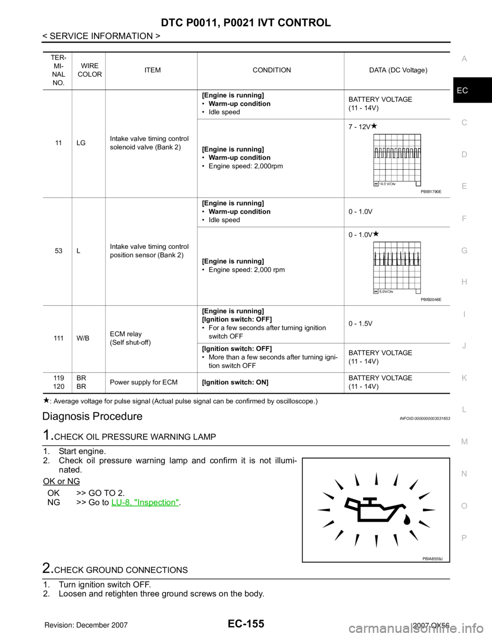
1.CHECK OIL PRESSURE WARNING LAMP
1. Start engine.
2. Check oil pressure warning lamp and confirm it is not illumi-
nated.
OK or NG
OK >> GO TO 2.
NG >> Go to LU-8, "
Inspection".
2.CHECK GROUND CONNECTIONS
1. Turn ignition switch OFF.
2. Loosen and retighten three ground screws on the body.
TER-
MI-
NAL
NO.WIRE
COLORITEM CONDITION DATA (DC Voltage)
11 L GIntake valve timing control
solenoid valve (Bank 2)[Engine is running]
•Warm-up condition
• Idle speedBATTERY VOLTAGE
(11 - 14V)
[Engine is running]
•Warm-up condition
• Engine speed: 2,000rpm7 - 12V
53 LIntake valve timing control
position sensor (Bank 2)[Engine is running]
•Warm-up condition
• Idle speed0 - 1.0V
[Engine is running]
• Engine speed: 2,000 rpm0 - 1.0V
111 W / BECM relay
(Self shut-off)[Engine is running]
[Ignition switch: OFF]
• For a few seconds after turning ignition
switch OFF0 - 1.5V
[Ignition switch: OFF]
• More than a few seconds after turning igni-
tion switch OFFBATTERY VOLTAGE
(11 - 14V)
11 9
120BR
BRPower supply for ECM[Ignition switch: ON]BATTERY VOLTAGE
(11 - 14V)
PBIB1790E
PBIB2046E
PBIA8559J
Page 1263 of 3061
EC-180
< SERVICE INFORMATION >
DTC P0075, P0081 IVT CONTROL SOLENOID VALVE
Do not use ECM ground terminals when measuring input/output voltage. Doing so may result in dam-
age to the ECM's transistor. Use a ground other than ECM terminals, such as the ground.
: Average voltage for pulse signal (Actual pulse signal can be confirmed by oscilloscope.)TER-
MI-
NAL
NO.WIRE
COLORITEM CONDITION DATA (DC Voltage)
10 WIntake valve timing control
solenoid valve (Bank 1)[Engine is running]
•Warm-up condition
• Idle speedBATTERY VOLTAGE
(11 - 14V)
[Engine is running]
•Warm-up condition
• Engine speed: 2,000rpm7 - 12V
111 W / BECM relay
(Self shut-off)[Engine is running]
[Ignition switch: OFF]
• For a few seconds after turning ignition
switch OFF0 - 1.5V
[Ignition switch: OFF]
• More than a few seconds after turning igni-
tion switch OFFBATTERY VOLTAGE
(11 - 14V)
11 9
120BR
BRPower supply for ECM[Ignition switch: ON]BATTERY VOLTAGE
(11 - 14V)
PBIB1790E
Page 1265 of 3061
EC-182
< SERVICE INFORMATION >
DTC P0075, P0081 IVT CONTROL SOLENOID VALVE
: Average voltage for pulse signal (Actual pulse signal can be confirmed by oscilloscope.)
Diagnosis ProcedureINFOID:0000000003531677
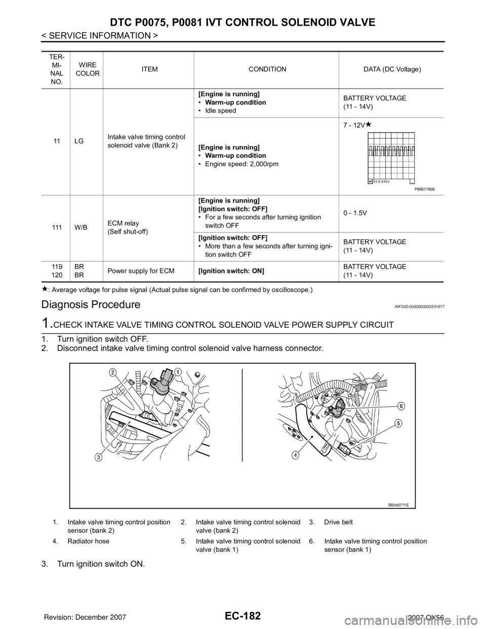
1.CHECK INTAKE VALVE TIMING CONTROL SOLENOID VALVE POWER SUPPLY CIRCUIT
1. Turn ignition switch OFF.
2. Disconnect intake valve timing control solenoid valve harness connector.
3. Turn ignition switch ON.
TER-
MI-
NAL
NO.WIRE
COLORITEM CONDITION DATA (DC Voltage)
11 L GIntake valve timing control
solenoid valve (Bank 2)[Engine is running]
•Warm-up condition
• Idle speedBATTERY VOLTAGE
(11 - 14V)
[Engine is running]
•Warm-up condition
• Engine speed: 2,000rpm7 - 12V
111 W / BECM relay
(Self shut-off)[Engine is running]
[Ignition switch: OFF]
• For a few seconds after turning ignition
switch OFF0 - 1.5V
[Ignition switch: OFF]
• More than a few seconds after turning igni-
tion switch OFFBATTERY VOLTAGE
(11 - 14V)
11 9
120BR
BRPower supply for ECM[Ignition switch: ON]BATTERY VOLTAGE
(11 - 14V)
PBIB1790E
1. Intake valve timing control position
sensor (bank 2)2. Intake valve timing control solenoid
valve (bank 2)3. Drive belt
4. Radiator hose 5. Intake valve timing control solenoid
valve (bank 1)6. Intake valve timing control position
sensor (bank 1)
BBIA0771E
Page 1273 of 3061

EC-190
< SERVICE INFORMATION >
DTC P0101 MAF SENSOR
Diagnosis Procedure
INFOID:0000000003531686
1.INSPECTION START
Which malfunction (A or B) is duplicated?
A or B
A>>GO TO 3.
B>>GO TO 2.
2.CHECK INTAKE SYSTEM
Check the following for connection.
• Air duct
• Vacuum hoses
• Intake air passage between air duct to intake manifold
OK or NG
OK >> GO TO 3.
NG >> Reconnect the parts.
3.CHECK GROUND CONNECTIONS
1. Turn ignition switch OFF.
2. Loosen and retighten three ground screws on the body.
Refer to EC-143, "
Ground Inspection".
OK or NG
OK >> GO TO 4.
NG >> Repair or replace ground connections.
TER-
MI-
NAL
NO.WIRE
COLORITEM CONDITION DATA (DC Voltage)
51 W Mass air flow sensor[Engine is running]
•Warm-up condition
• Idle speed1.0 - 1.3V
[Engine is running]
•Warm-up condition
• Engine speed: 2,500 rpm.1.7 - 2.1V
67 B Sensor ground[Engine is running]
•Warm-up condition
• Idle speedApproximately 0V
111 W / BECM relay
(Self shut-off)[Engine is running]
[Ignition switch: OFF]
• For a few seconds after turning ignition
switch OFF0 - 1.5V
[Ignition switch: OFF]
• More than a few seconds after turning igni-
tion switch OFFBATTERY VOLTAGE
(11 - 14V)
11 9
120BR
BRPower supply for ECM[Ignition switch: ON]BATTERY VOLTAGE
(11 - 14V)
BBIA0354E
Page 1280 of 3061
DTC P0102, P0103 MAF SENSOR
EC-197
< SERVICE INFORMATION >
C
D
E
F
G
H
I
J
K
L
MA
EC
N
P O
Diagnosis ProcedureINFOID:0000000003531694
1.INSPECTION START
Which malfunction (P0102 or P0103) is duplicated?
P0102 or P0103
P0102 >> GO TO 2.
P0103 >> GO TO 3.
2.CHECK INTAKE SYSTEM
Check the following for connection.
• Air duct
• Vacuum hoses
• Intake air passage between air duct to intake manifold
OK or NG
OK >> GO TO 3.
NG >> Reconnect the parts.
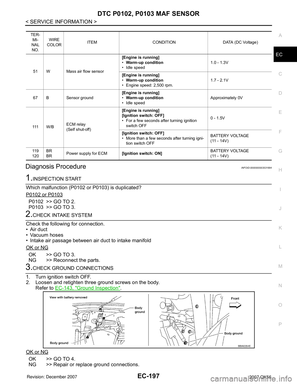
3.CHECK GROUND CONNECTIONS
1. Turn ignition switch OFF.
2. Loosen and retighten three ground screws on the body.
Refer to EC-143, "
Ground Inspection".
OK or NG
OK >> GO TO 4.
NG >> Repair or replace ground connections.
TER-
MI-
NAL
NO.WIRE
COLORITEM CONDITION DATA (DC Voltage)
51 W Mass air flow sensor[Engine is running]
•Warm-up condition
• Idle speed1.0 - 1.3V
[Engine is running]
•Warm-up condition
• Engine speed: 2,500 rpm.1.7 - 2.1V
67 B Sensor ground[Engine is running]
•Warm-up condition
• Idle speedApproximately 0V
111 W / BECM relay
(Self shut-off)[Engine is running]
[Ignition switch: OFF]
• For a few seconds after turning ignition
switch OFF0 - 1.5V
[Ignition switch: OFF]
• More than a few seconds after turning igni-
tion switch OFFBATTERY VOLTAGE
(11 - 14V)
11 9
120BR
BRPower supply for ECM[Ignition switch: ON]BATTERY VOLTAGE
(11 - 14V)
BBIA0354E
Page 1422 of 3061
DTC P0335 CKP SENSOR (POS)
EC-339
< SERVICE INFORMATION >
C
D
E
F
G
H
I
J
K
L
MA
EC
N
P O
Do not use ECM ground terminals when measuring input/output voltage. Doing so may result in dam-
age to the ECM's transistor. Use a ground other than ECM terminals, such as the ground.
: Average voltage for pulse signal (Actual pulse signal can be confirmed by oscilloscope.)
Diagnosis ProcedureINFOID:0000000003531837
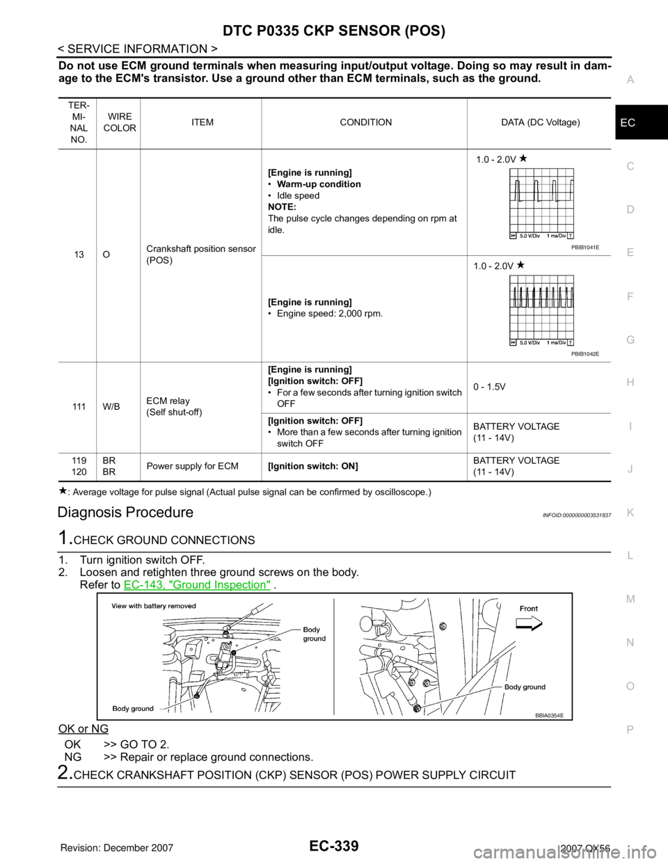
1.CHECK GROUND CONNECTIONS
1. Turn ignition switch OFF.
2. Loosen and retighten three ground screws on the body.
Refer to EC-143, "
Ground Inspection" .
OK or NG
OK >> GO TO 2.
NG >> Repair or replace ground connections.
2.CHECK CRANKSHAFT POSITION (CKP) SENSOR (POS) POWER SUPPLY CIRCUIT
TER-
MI-
NAL
NO.WIRE
COLORITEM CONDITION DATA (DC Voltage)
13 OCrankshaft position sensor
(POS)[Engine is running]
•Warm-up condition
• Idle speed
NOTE:
The pulse cycle changes depending on rpm at
idle. 1.0 - 2.0V
[Engine is running]
• Engine speed: 2,000 rpm.1.0 - 2.0V
111 W / BECM relay
(Self shut-off)[Engine is running]
[Ignition switch: OFF]
• For a few seconds after turning ignition switch
OFF0 - 1.5V
[Ignition switch: OFF]
• More than a few seconds after turning ignition
switch OFFBATTERY VOLTAGE
(11 - 14V)
11 9
120BR
BRPower supply for ECM[Ignition switch: ON]BATTERY VOLTAGE
(11 - 14V)
PBIB1041E
PBIB1042E
BBIA0354E
Page 1428 of 3061
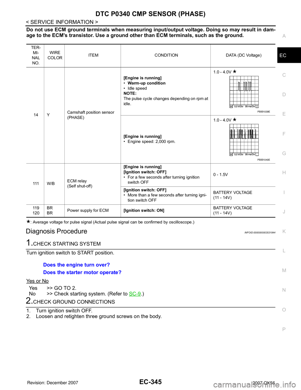
DTC P0340 CMP SENSOR (PHASE)
EC-345
< SERVICE INFORMATION >
C
D
E
F
G
H
I
J
K
L
MA
EC
N
P O
Do not use ECM ground terminals when measuring input/output voltage. Doing so may result in dam-
age to the ECM's transistor. Use a ground other than ECM terminals, such as the ground.
: Average voltage for pulse signal (Actual pulse signal can be confirmed by oscilloscope.)
Diagnosis ProcedureINFOID:0000000003531844
1.CHECK STARTING SYSTEM
Turn ignition switch to START position.
Ye s o r N o
Yes >> GO TO 2.
No >> Check starting system. (Refer to SC-9
.)
2.CHECK GROUND CONNECTIONS
1. Turn ignition switch OFF.
2. Loosen and retighten three ground screws on the body.
TER-
MI-
NAL
NO.WIRE
COLORITEM CONDITION DATA (DC Voltage)
14 YCamshaft position sensor
(PHASE)[Engine is running]
•Warm-up condition
• Idle speed
NOTE:
The pulse cycle changes depending on rpm at
idle.1.0 - 4.0V
[Engine is running]
• Engine speed: 2,000 rpm.1.0 - 4.0V
111 W / BECM relay
(Self shut-off)[Engine is running]
[Ignition switch: OFF]
• For a few seconds after turning ignition
switch OFF0 - 1.5V
[Ignition switch: OFF]
• More than a few seconds after turning igni-
tion switch OFFBATTERY VOLTAGE
(11 - 14V)
11 9
120BR
BRPower supply for ECM[Ignition switch: ON]BATTERY VOLTAGE
(11 - 14V)
PBIB1039E
PBIB1040E
Does the engine turn over?
Does the starter motor operate?
Page 1452 of 3061

DTC P0443 EVAP CANISTER PURGE VOLUME CONTROL SOLENOID VALVE
EC-369
< SERVICE INFORMATION >
C
D
E
F
G
H
I
J
K
L
MA
EC
N
P O
Do not use ECM ground terminals when measuring input/output voltage. Doing so may result in dam-
age to the ECM's transistor. Use a ground other than ECM terminals, such as the ground.
: Average voltage for pulse signal (Actual pulse signal can be confirmed by oscilloscope.)
Diagnosis ProcedureINFOID:0000000003531864
1.CHECK EVAP CANISTER PURGE VOLUME CONTROL SOLENOID VALVE POWER SUPPLY CIRCUIT
1. Turn ignition switch OFF.
2. Disconnect EVAP canister purge volume control solenoid valve
harness connector.
3. Turn ignition switch ON.
TER-
MI-
NAL
NO.WIRE
COLORITEM CONDITION DATA (DC Voltage)
45 L/YEVAP canister purge volume
control solenoid valve[Engine is running]
• Idle speed
• Accelerator pedal: Not depressed even
slightly, after starting engineBATTERY VOLTAGE
(11 - 14V)
[Engine is running]
• Engine speed: About 2,000 rpm (More than
100 seconds after starting engine)11 - 1 4 V
111 W / BECM relay
(Self shut-off)[Engine is running]
[Ignition switch: OFF]
• For a few seconds after turning ignition
switch OFF0 - 1.5V
[Ignition switch: OFF]
• More than a few seconds after turning igni-
tion switch OFFBATTERY VOLTAGE
(11 - 14V)
11 9
120BR
BRPower supply for ECM[Ignition switch: ON]BATTERY VOLTAGE
(11 - 14V)
PBIB0050E
PBIB0051E
BBIA0366E