Page 1355 of 4647
![INFINITI M35 2007 Factory Service Manual BRC-54
[VDC/TCS/ABS]
WHEEL SENSOR
Revision: 2007 April2007 M35/M45
WHEEL SENSORPFP:47910
Removal and InstallationNFS000RA
COMPONENT
NOTE:
The above figure (front side) shows left side. Right side is t](/manual-img/42/57024/w960_57024-1354.png "INFINITI M35 2007 Factory Service Manual BRC-54
[VDC/TCS/ABS]
WHEEL SENSOR
Revision: 2007 April2007 M35/M45
WHEEL SENSORPFP:47910
Removal and InstallationNFS000RA
COMPONENT
NOTE:
The above figure (front side) shows left side. Right side is t")
BRC-54
[VDC/TCS/ABS]
WHEEL SENSOR
Revision: 2007 April2007 M35/M45
WHEEL SENSORPFP:47910
Removal and InstallationNFS000RA
COMPONENT
NOTE:
The above figure (front side) shows left side. Right side is the mirror image.
REMOVAL
Pay attention to the following when removing sensor.
CAUTION:
�Do not twist sensor harness as much as possible, when removing it. Pull sensors out without pull-
ing on sensor harness.
�Take care to avoid damaging sensor edges or rotor teeth. Remove wheel sensor first before
removing front or rear wheel hub. This is to avoid damage to sensor wiring and loss of sensor
function.
INSTALLATION
Pay attention to the following when installing wheel sensor. Tighten installation bolts to the specified torques.
Refer to BRC-54, "
COMPONENT" .
1. Front LH wheel sensor 2. Front LH wheel sensor connector 3. Clamp
4. Bracket 5. Rear RH wheel sensor connector 6. Rear LH wheel sensor connector
7. Rear LH wheel sensor 8. Rear RH wheel sensor
A. Front side B. Rear side : Front
Refer to GI section GI-11, "
Components" for symbol marks in the figure.
SFIA2723J
Page 1356 of 4647
WHEEL SENSOR
BRC-55
[VDC/TCS/ABS]
C
D
E
G
H
I
J
K
L
MA
B
BRC
Revision: 2007 April2007 M35/M45
�When installing, make sure there is no foreign material such as iron chips on and in the mounting hole of
the wheel sensor. Make sure no foreign material has been caught in the sensor rotor. Remove any foreign
material and clean the mount.
�When installing wheel sensor, be sure to press rubber grommets in until they lock at locations shown
above in the figure. When installed, harness must not be twisted.
Page 1357 of 4647
BRC-56
[VDC/TCS/ABS]
SENSOR ROTOR
Revision: 2007 April2007 M35/M45
SENSOR ROTORPFP:47970
Removal and InstallationNFS000RB
REMOVAL
CAUTION:
Do not reuse sensor rotor.
Front
�Sensor rotor cannot be disassembled. Remove the sensor rotor together with hub bearing assembly.
Refer to FAX-5, "
REMOVAL" .
Rear
�Follow the procedure below to remove rear sensor rotor.
–Remove side flange. Refer to RFD-14, "SIDE OIL SEAL" .
–Using a bearing replacer (suitable tool) and puller (suitable tool), remove sensor rotor from side flange.
INSTALLATION
Front
�Sensor rotor cannot be disassembled. Remove the sensor rotor together with hub bearing assembly.
Refer to FAX-7, "
INSTALLATION" .
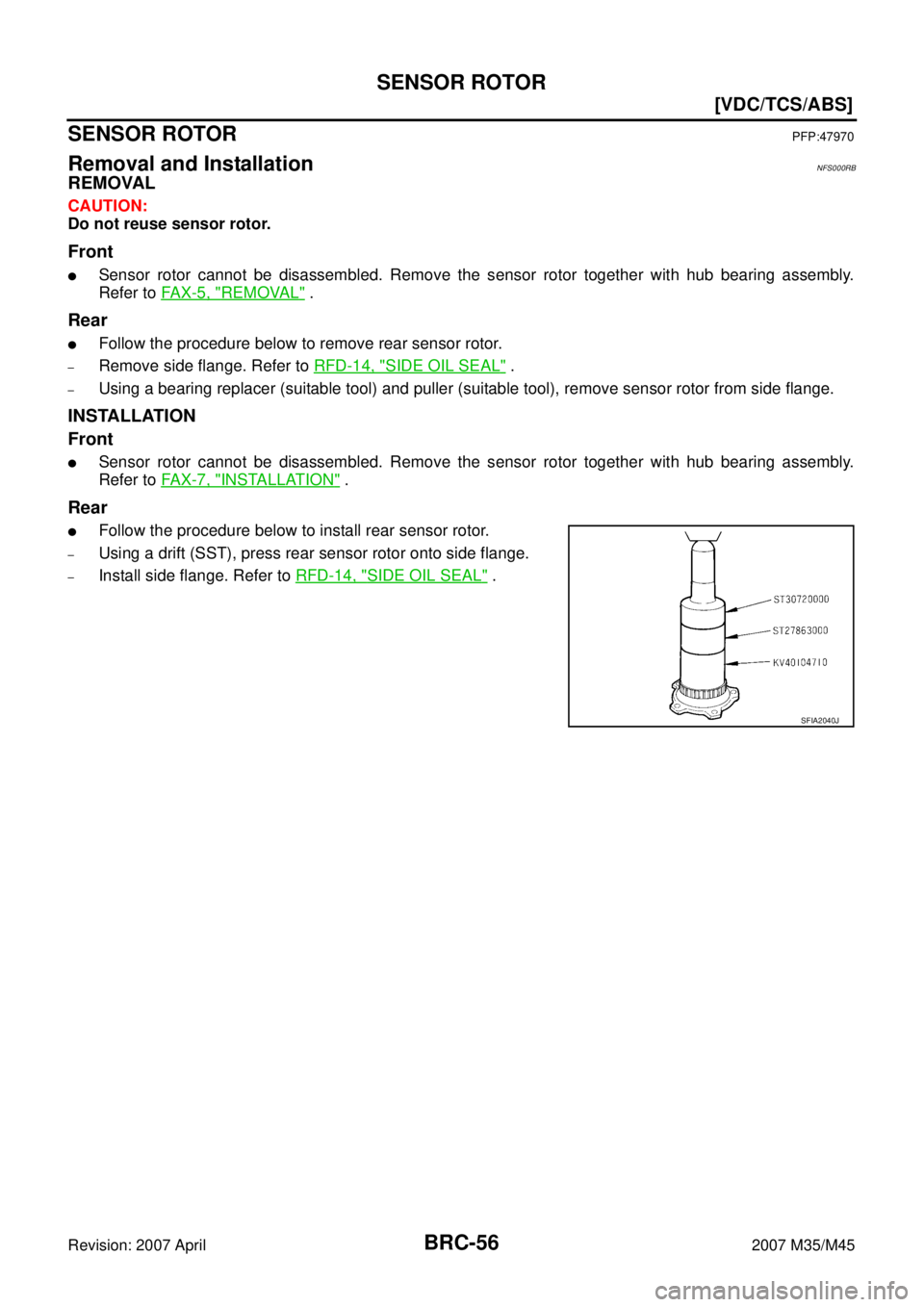
Rear
�Follow the procedure below to install rear sensor rotor.
–Using a drift (SST), press rear sensor rotor onto side flange.
–Install side flange. Refer to RFD-14, "SIDE OIL SEAL" .
SFIA2040J
Page 1358 of 4647
![INFINITI M35 2007 Factory Service Manual ACTUATOR AND ELECTRIC UNIT (ASSEMBLY)
BRC-57
[VDC/TCS/ABS]
C
D
E
G
H
I
J
K
L
MA
B
BRC
Revision: 2007 April2007 M35/M45
ACTUATOR AND ELECTRIC UNIT (ASSEMBLY)PFP:47660
Removal and InstallationNFS000RC
C](/manual-img/42/57024/w960_57024-1357.png "INFINITI M35 2007 Factory Service Manual ACTUATOR AND ELECTRIC UNIT (ASSEMBLY)
BRC-57
[VDC/TCS/ABS]
C
D
E
G
H
I
J
K
L
MA
B
BRC
Revision: 2007 April2007 M35/M45
ACTUATOR AND ELECTRIC UNIT (ASSEMBLY)PFP:47660
Removal and InstallationNFS000RC
C")
ACTUATOR AND ELECTRIC UNIT (ASSEMBLY)
BRC-57
[VDC/TCS/ABS]
C
D
E
G
H
I
J
K
L
MA
B
BRC
Revision: 2007 April2007 M35/M45
ACTUATOR AND ELECTRIC UNIT (ASSEMBLY)PFP:47660
Removal and InstallationNFS000RC
COMPONENT
CAUTION:
Be careful of the following.
�Before servicing, disconnect the battery cable from negative terminal.
�To remove brake tube, use a flare nut wrench to prevent flare nuts and brake tube from being dam-
aged. To install, use flare nut torque wrench.
�Do not apply excessive impact to ABS actuator and electric unit (control unit), such as dropping it.
�Do not remove and install actuator by holding harness.
�After work is completed, bleed air from brake tube. Refer to BR-10, "Bleeding Brake System" .
�After installing harness connector in the ABS actuator and electric unit (control unit), make sure
connector is securely locked.
REMOVAL
1. Remove cowl top cover. Refer to EI-18, "REMOVAL" .
2. Disconnect ABS actuator and electric unit (control unit) connector.
3. Loosen brake tube flare nuts, then remove brake tubes from ABS actuator and electric unit (control unit).
4. Remove tire.
5. Remove fender protector (rear): (front LH side). Refer to EI-20, "
REMOVAL" .
6. Remove ABS actuator and electric unit (control unit) bracket mounting nut.
1. ABS actuator and electric unit (con-
trol unit)2. Connector 3. To front RH brake caliper
4. To rear LH brake caliper 5. To rear RH brake caliper 6. To front LH brake caliper
7. From master cylinder primary side 8. From master cylinder secondary side 9. Bushing
10. Bracket A. Left side of dash panel
Refer to GI section GI-11, "
Components" for symbol marks in the figure.
SFIA3018E
Page 1359 of 4647
BRC-58
[VDC/TCS/ABS]
ACTUATOR AND ELECTRIC UNIT (ASSEMBLY)
Revision: 2007 April2007 M35/M45
7. Remove ABS actuator and electric unit (control unit) from vehicle.
INSTALLATION
Installation is the reverse order of removal.
CAUTION:
When replacing ABS actuator and electric unit (control unit), make sure to adjust neutral position of
steering angle sensor. Refer to BRC-6, "
Adjustment of Steering Angle Sensor Neutral Position"
Page 1360 of 4647
G-SENSOR
BRC-59
[VDC/TCS/ABS]
C
D
E
G
H
I
J
K
L
MA
B
BRC
Revision: 2007 April2007 M35/M45
G-SENSORPFP:47930
Removal and InstallationNFS000RD
CAUTION:
�Do not drop or strike yaw rate/side G sensor, because it has little endurance to impact.
�Do not use power tool etc., because yaw rate/side G sensor is sensitive for the impact.
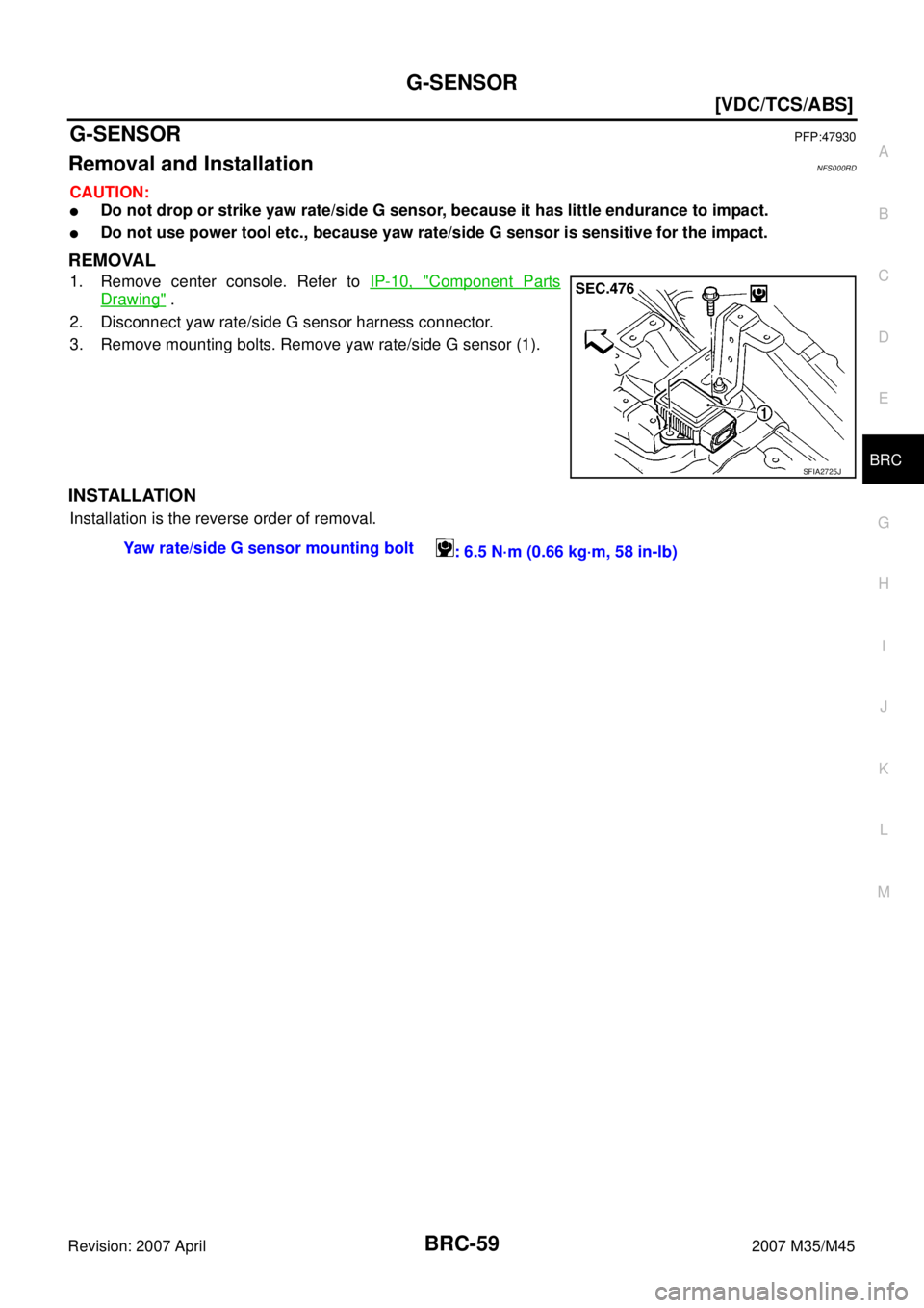
REMOVAL
1. Remove center console. Refer to IP-10, "Component Parts
Drawing" .
2. Disconnect yaw rate/side G sensor harness connector.
3. Remove mounting bolts. Remove yaw rate/side G sensor (1).
INSTALLATION
Installation is the reverse order of removal.
SFIA2725J
Yaw rate/side G sensor mounting bolt
: 6.5 N·m (0.66 kg·m, 58 in-lb)
Page 1361 of 4647
BRC-60
[VDC/TCS/ABS]
STEERING ANGLE SENSOR
Revision: 2007 April2007 M35/M45
STEERING ANGLE SENSORPFP:25554
Removal and InstallationNFS000RE
REMOVAL
1. Remove spiral cable assembly. Refer to SRS-44, "SPIRAL CABLE" .
2. Remove steering angle sensor from spiral cable assembly.
INSTALLATION
Installation is the reverse order of removal.
CAUTION:
After work, make sure to adjust neutral position of steering angle sensor. Refer to BRC-6, "
Adjustment
of Steering Angle Sensor Neutral Position" .
SFIA1404E
Page 1428 of 4647

COMBINATION METERS
DI-9
C
D
E
F
G
H
I
J
L
MA
B
DI
Revision: 2007 April2007 M35/M45
FA I L - S A F E
Combination meter performs fail-safe operation when unified meter and A/C amp. communication is malfunc-
tion.
Solution for communication error between the unified meter and A/C amp. and combination meter
Function Specifications
Speedometer
Reset to zero by suspending communication. Tachometer
Fuel gauge
Water temperature gauge
Illumination control Meter illumination When suspending communication, change to nighttime mode.
Dot matrix LCDPush engine starter
The display turns off by suspending communication. A/T position
ICC system
Buzzer The buzzer turns off by suspending communication.
Warning lamp/indicator lampABS warning lamp
The lamp turns on by suspending communication. Brake warning lamp
CRUISE warning lamp
VDC OFF indicator lamp
SLIP indicator lamp
A/T CHECK warning lamp
The lamp turns off by suspending communication. AWD warning lamp
Oil pressure warning lamp
Door warning lamp
Malfunction indicator lamp
CRUISE indicator lamp
SET indicator lamp
Low tire pressure warning lamp
AFS OFF indicator lamp
Front fog indicator lamp
High beam indicator
Turn signal indicator lamp
Key warning lamp

![INFINITI M35 2007 Factory Service Manual BRC-58
[VDC/TCS/ABS]
ACTUATOR AND ELECTRIC UNIT (ASSEMBLY)
Revision: 2007 April2007 M35/M45
7. Remove ABS actuator and electric unit (control unit) from vehicle.
INSTALLATION
Installation is the rever](/manual-img/42/57024/w960_57024-1358.png "INFINITI M35 2007 Factory Service Manual BRC-58
[VDC/TCS/ABS]
ACTUATOR AND ELECTRIC UNIT (ASSEMBLY)
Revision: 2007 April2007 M35/M45
7. Remove ABS actuator and electric unit (control unit) from vehicle.
INSTALLATION
Installation is the rever")
![INFINITI M35 2007 Factory Service Manual BRC-60
[VDC/TCS/ABS]
STEERING ANGLE SENSOR
Revision: 2007 April2007 M35/M45
STEERING ANGLE SENSORPFP:25554
Removal and InstallationNFS000RE
REMOVAL
1. Remove spiral cable assembly. Refer to SRS-44, "S](/manual-img/42/57024/w960_57024-1360.png "INFINITI M35 2007 Factory Service Manual BRC-60
[VDC/TCS/ABS]
STEERING ANGLE SENSOR
Revision: 2007 April2007 M35/M45
STEERING ANGLE SENSORPFP:25554
Removal and InstallationNFS000RE
REMOVAL
1. Remove spiral cable assembly. Refer to SRS-44, \"S")