Page 3232 of 4647
POWER WINDOW SYSTEM
GW-33
C
D
E
F
G
H
J
K
L
MA
B
GW
Revision: 2007 April2007 M35/M45
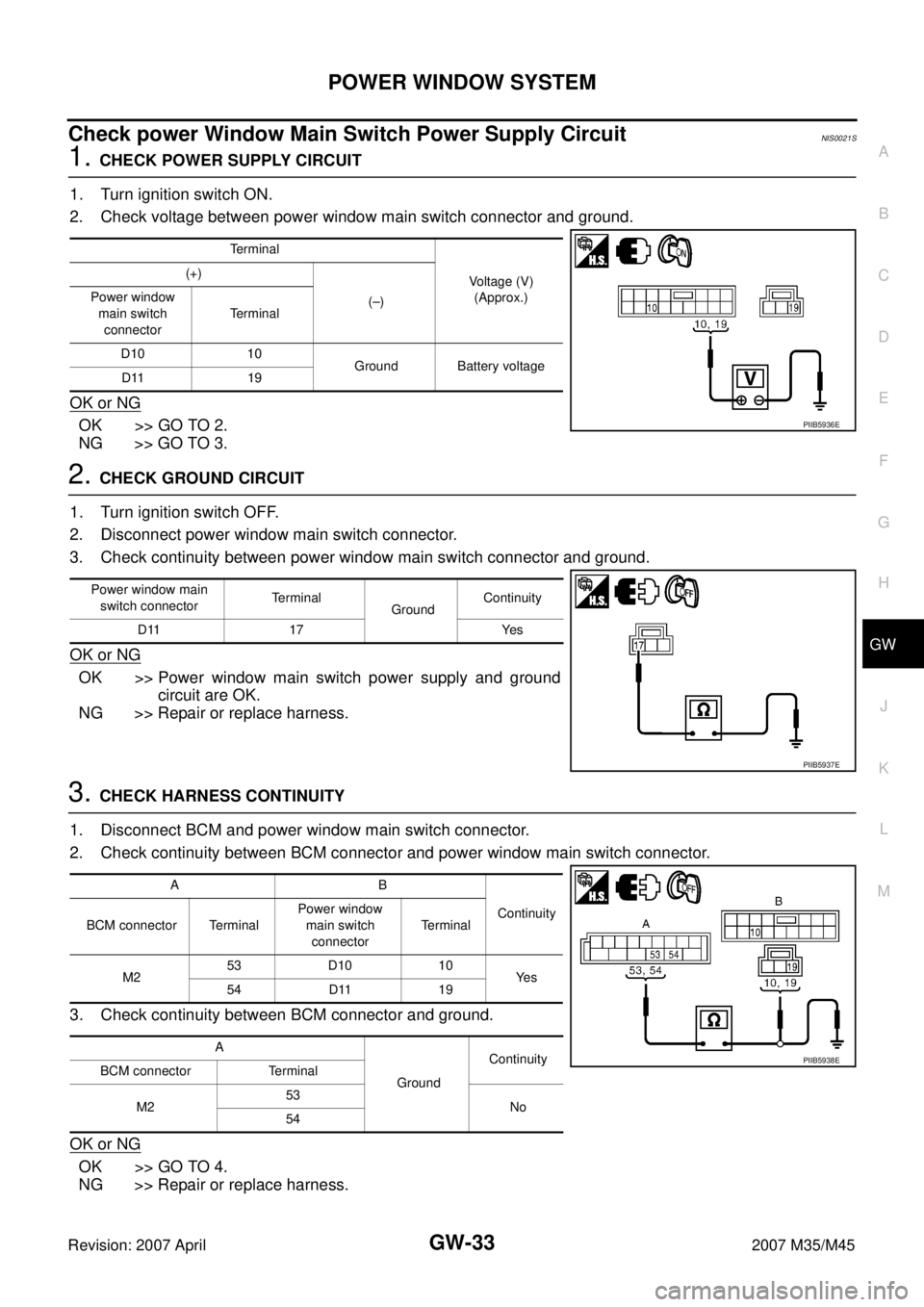
Check power Window Main Switch Power Supply Circuit NIS0021S
1. CHECK POWER SUPPLY CIRCUIT
1. Turn ignition switch ON.
2. Check voltage between power window main switch connector and ground.
OK or NG
OK >> GO TO 2.
NG >> GO TO 3.
2. CHECK GROUND CIRCUIT
1. Turn ignition switch OFF.
2. Disconnect power window main switch connector.
3. Check continuity between power window main switch connector and ground.
OK or NG
OK >> Power window main switch power supply and ground
circuit are OK.
NG >> Repair or replace harness.
3. CHECK HARNESS CONTINUITY
1. Disconnect BCM and power window main switch connector.
2. Check continuity between BCM connector and power window main switch connector.
3. Check continuity between BCM connector and ground.
OK or NG
OK >> GO TO 4.
NG >> Repair or replace harness.
Terminal
Voltage (V)
(Approx.) (+)
(–) Power window
main switch
connectorTerminal
D10 10
Ground Battery voltage
D11 19
PIIB5936E
Power window main
switch connectorTerminal
GroundContinuity
D11 17 Yes
PIIB5937E
AB
Continuity
BCM connector TerminalPower window
main switch
connectorTerminal
M253 D10 10
Ye s
54 D11 19
A
GroundContinuity
BCM connector Terminal
M253
No
54
PIIB5938E
Page 3233 of 4647

GW-34
POWER WINDOW SYSTEM
Revision: 2007 April2007 M35/M45
4. CHECK BCM OUTPUT SIGNAL
1. Connect BCM connector.
2. Turn ignition switch ON.
3. Check voltage between BCM connector and ground.
OK or NG
OK >> Check condition of harness and connector.
NG >> Replace BCM.
Check power Window Sub-Switch (Front Passenger Side) Power Supply and
Ground Circuit
NIS0021T
1. CHECK POWER SUPPLY CIRCUIT
1. Turn ignition switch OFF.
2. Check voltage between power window sub-switch (front passenger side) connector and ground
OK or NG
OK >> GO TO 2.
NG >> GO TO 3.
2. CHECK GROUND CIRCUIT
1. Disconnect power window sub-switch (front passenger side) connector.
2. Check continuity between power window sub-switch (front passenger side) connector and ground.
OK or NG
OK >> Power window sub-switch (front passenger side) power
supply and ground circuit are OK.
NG >> Repair or replace harness.
Terminals
Voltage (V)
(Approx.) (+)
(–)
BCM connector Terminal
M253
Ground Battery voltage
54
PIIB5939E
Terminal
Voltage (V)
(Approx.) (+)
(–) Power window
sub-switch
(front passenger side)
connectorTerminal
D46 10 Ground Battery voltage
PIIB5940E
Power window
sub-switch
(front passenger side)
connectorTerminal
GroundContinuity
D46 11 Yes
PIIB5941E
Page 3234 of 4647
POWER WINDOW SYSTEM
GW-35
C
D
E
F
G
H
J
K
L
MA
B
GW
Revision: 2007 April2007 M35/M45
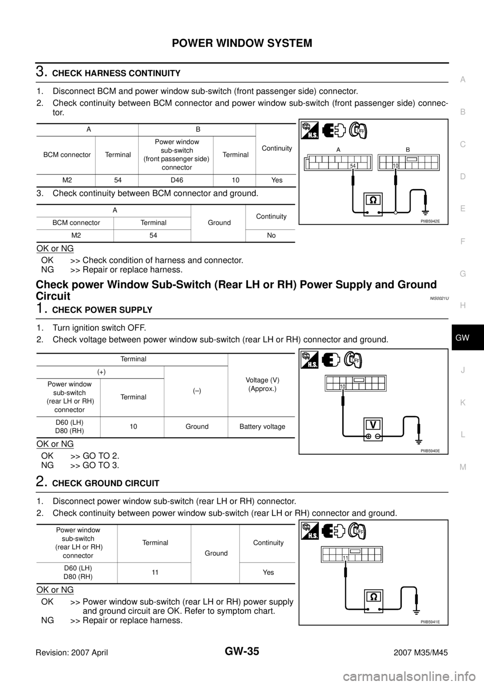
3. CHECK HARNESS CONTINUITY
1. Disconnect BCM and power window sub-switch (front passenger side) connector.
2. Check continuity between BCM connector and power window sub-switch (front passenger side) connec-
tor.
3. Check continuity between BCM connector and ground.
OK or NG
OK >> Check condition of harness and connector.
NG >> Repair or replace harness.
Check power Window Sub-Switch (Rear LH or RH) Power Supply and Ground
Circuit
NIS0021U
1. CHECK POWER SUPPLY
1. Turn ignition switch OFF.
2. Check voltage between power window sub-switch (rear LH or RH) connector and ground.
OK or NG
OK >> GO TO 2.
NG >> GO TO 3.
2. CHECK GROUND CIRCUIT
1. Disconnect power window sub-switch (rear LH or RH) connector.
2. Check continuity between power window sub-switch (rear LH or RH) connector and ground.
OK or NG
OK >> Power window sub-switch (rear LH or RH) power supply
and ground circuit are OK. Refer to symptom chart.
NG >> Repair or replace harness.
AB
Continuity
BCM connector TerminalPower window
sub-switch
(front passenger side)
connectorTerminal
M2 54 D46 10 Yes
A
GroundContinuity
BCM connector Terminal
M2 54 No
PIIB5942E
Terminal
Voltage (V)
(Approx.) (+)
(–) Power window
sub-switch
(rear LH or RH)
connectorTerminal
D60 (LH)
D80 (RH)10 Ground Battery voltage
PIIB5940E
Power window
sub-switch
(rear LH or RH)
connectorTerminal
GroundContinuity
D60 (LH)
D80 (RH)11 Ye s
PIIB5941E
Page 3235 of 4647
GW-36
POWER WINDOW SYSTEM
Revision: 2007 April2007 M35/M45
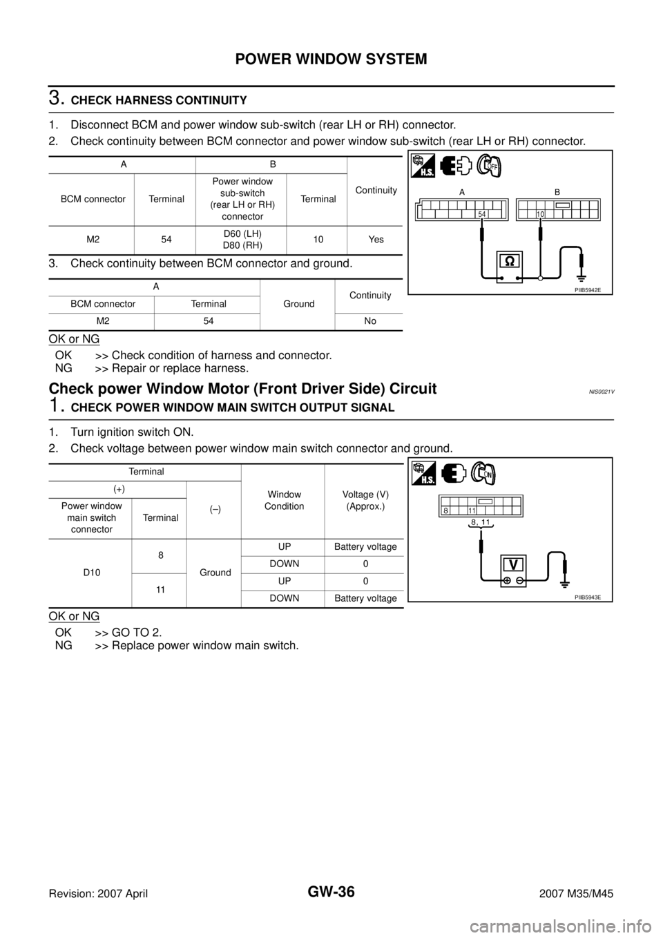
3. CHECK HARNESS CONTINUITY
1. Disconnect BCM and power window sub-switch (rear LH or RH) connector.
2. Check continuity between BCM connector and power window sub-switch (rear LH or RH) connector.
3. Check continuity between BCM connector and ground.
OK or NG
OK >> Check condition of harness and connector.
NG >> Repair or replace harness.
Check power Window Motor (Front Driver Side) Circuit NIS0021V
1. CHECK POWER WINDOW MAIN SWITCH OUTPUT SIGNAL
1. Turn ignition switch ON.
2. Check voltage between power window main switch connector and ground.
OK or NG
OK >> GO TO 2.
NG >> Replace power window main switch.
AB
Continuity
BCM connector TerminalPower window
sub-switch
(rear LH or RH)
connectorTerminal
M2 54D60 (LH)
D80 (RH)10 Yes
A
GroundContinuity
BCM connector Terminal
M2 54 No
PIIB5942E
Terminal
Window
ConditionVoltage (V)
(Approx.) (+)
(–) Power window
main switch
connectorTerminal
D108
GroundUP Battery voltage
DOWN 0
11UP 0
DOWN Battery voltage
PIIB5943E
Page 3236 of 4647
POWER WINDOW SYSTEM
GW-37
C
D
E
F
G
H
J
K
L
MA
B
GW
Revision: 2007 April2007 M35/M45
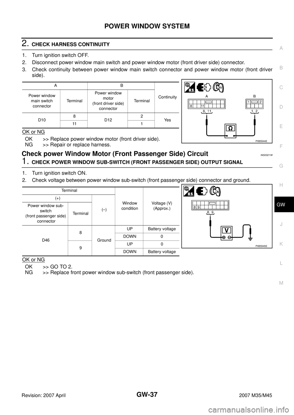
2. CHECK HARNESS CONTINUITY
1. Turn ignition switch OFF.
2. Disconnect power window main switch and power window motor (front driver side) connector.
3. Check continuity between power window main switch connector and power window motor (front driver
side).
OK or NG
OK >> Replace power window motor (front driver side).
NG >> Repair or replace harness.
Check power Window Motor (Front Passenger Side) Circuit NIS0021W
1. CHECK POWER WINDOW SUB-SWITCH (FRONT PASSENGER SIDE) OUTPUT SIGNAL
1. Turn ignition switch ON.
2. Check voltage between power window sub-switch (front passenger side) connector and ground.
OK or NG
OK >> GO TO 2.
NG >> Replace front power window sub-switch (front passenger side).
AB
Continuity Power window
main switch
connectorTerminalPower window
motor
(front driver side)
connectorTerminal
D108
D122
Ye s
11 1
PIIB5944E
Terminal
Window
conditionVoltage (V)
(Approx.) (+)
(–) Power window sub-
switch
(front passenger side)
connectorTerminal
D468
GroundUP Battery voltage
DOWN 0
9UP 0
DOWN Battery voltage
PIIB5945E
Page 3237 of 4647
GW-38
POWER WINDOW SYSTEM
Revision: 2007 April2007 M35/M45
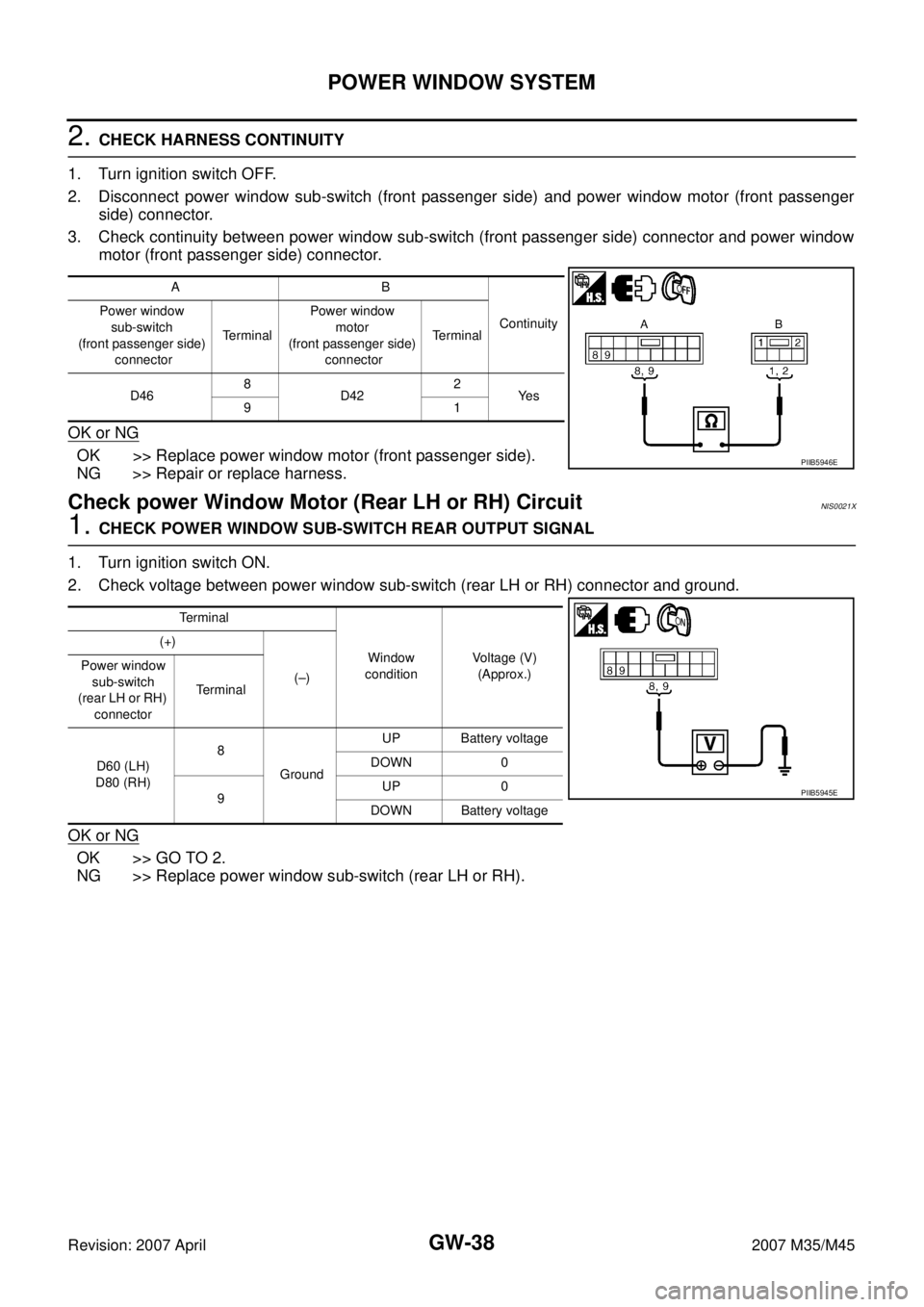
2. CHECK HARNESS CONTINUITY
1. Turn ignition switch OFF.
2. Disconnect power window sub-switch (front passenger side) and power window motor (front passenger
side) connector.
3. Check continuity between power window sub-switch (front passenger side) connector and power window
motor (front passenger side) connector.
OK or NG
OK >> Replace power window motor (front passenger side).
NG >> Repair or replace harness.
Check power Window Motor (Rear LH or RH) Circuit NIS0021X
1. CHECK POWER WINDOW SUB-SWITCH REAR OUTPUT SIGNAL
1. Turn ignition switch ON.
2. Check voltage between power window sub-switch (rear LH or RH) connector and ground.
OK or NG
OK >> GO TO 2.
NG >> Replace power window sub-switch (rear LH or RH).
AB
Continuity Power window
sub-switch
(front passenger side)
connectorTerminalPower window
motor
(front passenger side)
connectorTerminal
D468
D422
Ye s
91
PIIB5946E
Terminal
Window
conditionVoltage (V)
(Approx.) (+)
(–) Power window
sub-switch
(rear LH or RH)
connectorTerminal
D60 (LH)
D80 (RH)8
GroundUP Battery voltage
DOWN 0
9UP 0
DOWN Battery voltage
PIIB5945E
Page 3249 of 4647
GW-50
POWER WINDOW SYSTEM
Revision: 2007 April2007 M35/M45
Check door Switch NIS00221
1. CHECK DOOR SWITCH INPUT SIGNAL
With CONSULT-II
Check (“DOOR SW-DR” and “DOOR SW-AS”) in “DATA MONITOR” mode with CONSULT-II.
Without CONSULT-II
Check voltage between BCM connector and ground.
OK or NG
OK >> Door switch circuit is OK.
NG >> GO TO 2.
Monitor item Condition
DOOR SW-DROPEN : ON
CLOSE : OFF
DOOR SW-ASOPEN : ON
CLOSE : OFF
PIIA2464E
Terminals
Door conditionVoltage (V)
(Approx.) (+)
(–) BCM
connec-
torTerminal
M1 12
GroundPassenger
sideOPEN 0
CLOSE Battery voltage
M3 62 Driver sideOPEN 0
CLOSE Battery voltage
PIIB5955E
Page 3250 of 4647
POWER WINDOW SYSTEM
GW-51
C
D
E
F
G
H
J
K
L
MA
B
GW
Revision: 2007 April2007 M35/M45
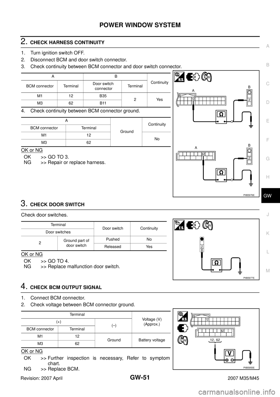
2. CHECK HARNESS CONTINUITY
1. Turn ignition switch OFF.
2. Disconnect BCM and door switch connector.
3. Check continuity between BCM connector and door switch connector.
4. Check continuity between BCM connector ground.
OK or NG
OK >> GO TO 3.
NG >> Repair or replace harness.
3. CHECK DOOR SWITCH
Check door switches.
OK or NG
OK >> GO TO 4.
NG >> Replace malfunction door switch.
4. CHECK BCM OUTPUT SIGNAL
1. Connect BCM connector.
2. Check voltage between BCM connector ground.
OK or NG
OK >> Further inspection is necessary, Refer to symptom
chart.
NG >> Replace BCM.
AB
Continuity
BCM connector TerminalDoor switch
connectorTerminal
M1 12 B35
2Yes
M3 62 B11
A
GroundContinuity
BCM connector Terminal
M1 12
No
M3 62
PIIB5976E
Terminal
Door switch Continuity
Door switches
2Ground part of
door switchPushed No
Released Yes
PIIB5977E
Terminal
Voltage (V)
(Approx.) (+)
(–)
BCM connector Terminal
M1 12
Ground Battery voltage
M3 62
PIIB5955E