Page 1451 of 4647

DI-32
UNIFIED METER AND A/C AMP
Revision: 2007 April2007 M35/M45
DATA MONITOR
Operation Procedure
1. Touch “METER A/C AMP” on “SELECT SYSTEM” screen.
2. Touch “DATA MONITOR” on “SELECT DIAG MODE” screen.
3. Touch either “MAIN SIGNALS” or “SELECTION FROM MENU” on the “DATA MONITOR” screen.
4. When “SELECTION FROM MENU” is selected, touch individual items to be monitored. When “MAIN SIG-
NALS” is selected, main items will be monitored.
5. Touch “START”.
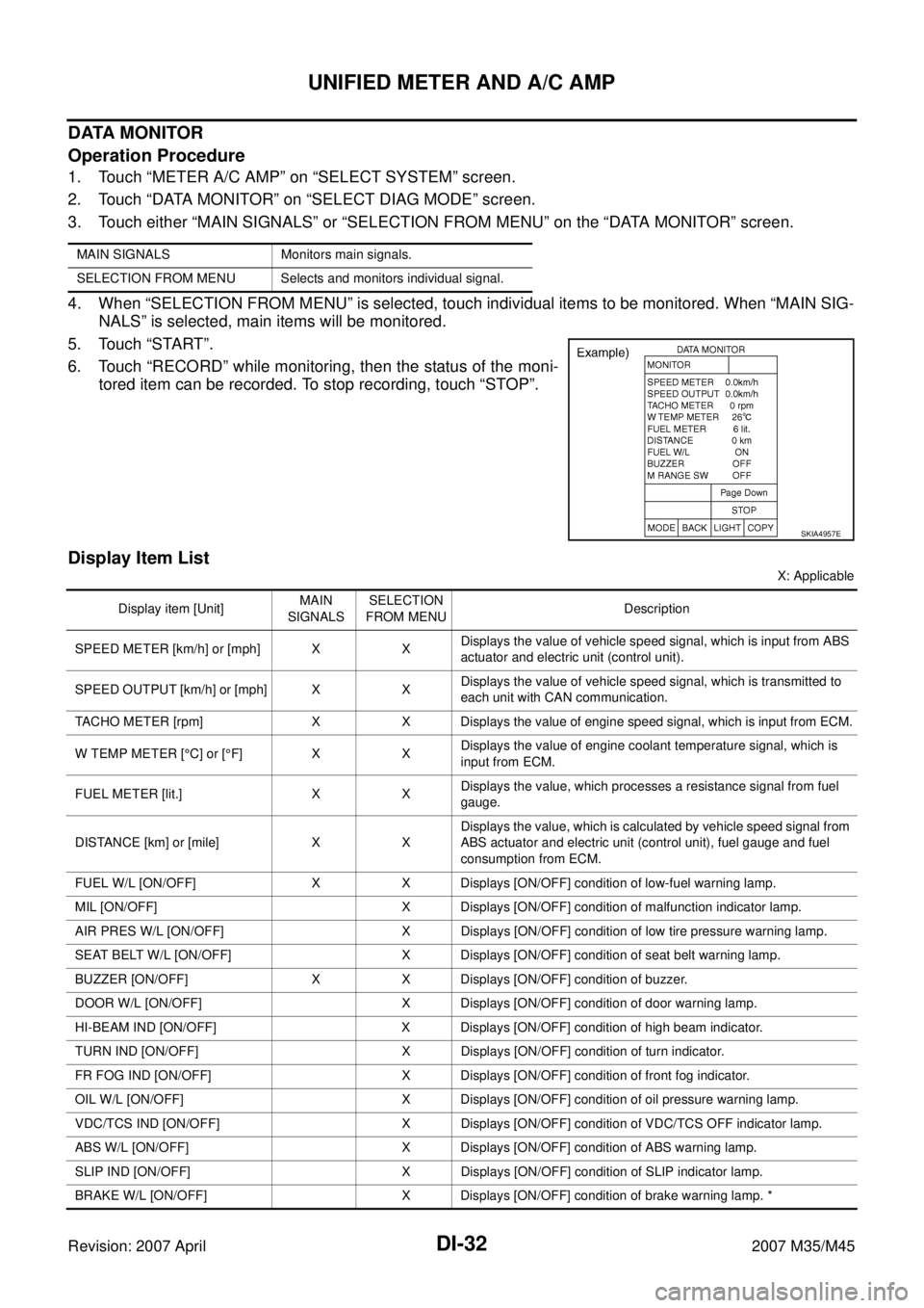
6. Touch “RECORD” while monitoring, then the status of the moni-
tored item can be recorded. To stop recording, touch “STOP”.
Display Item List
X: Applicable MAIN SIGNALS Monitors main signals.
SELECTION FROM MENU Selects and monitors individual signal.
SKIA4957E
Display item [Unit]MAIN
SIGNALSSELECTION
FROM MENUDescription
SPEED METER [km/h] or [mph] X XDisplays the value of vehicle speed signal, which is input from ABS
actuator and electric unit (control unit).
SPEED OUTPUT [km/h] or [mph] X XDisplays the value of vehicle speed signal, which is transmitted to
each unit with CAN communication.
TACHO METER [rpm] X X Displays the value of engine speed signal, which is input from ECM.
W TEMP METER [°C] or [°F] X XDisplays the value of engine coolant temperature signal, which is
input from ECM.
FUEL METER [lit.] X XDisplays the value, which processes a resistance signal from fuel
gauge.
DISTANCE [km] or [mile] X XDisplays the value, which is calculated by vehicle speed signal from
ABS actuator and electric unit (control unit), fuel gauge and fuel
consumption from ECM.
FUEL W/L [ON/OFF] X X Displays [ON/OFF] condition of low-fuel warning lamp.
MIL [ON/OFF] X Displays [ON/OFF] condition of malfunction indicator lamp.
AIR PRES W/L [ON/OFF] X Displays [ON/OFF] condition of low tire pressure warning lamp.
SEAT BELT W/L [ON/OFF] X Displays [ON/OFF] condition of seat belt warning lamp.
BUZZER [ON/OFF] X X Displays [ON/OFF] condition of buzzer.
DOOR W/L [ON/OFF] X Displays [ON/OFF] condition of door warning lamp.
HI-BEAM IND [ON/OFF] X Displays [ON/OFF] condition of high beam indicator.
TURN IND [ON/OFF] X Displays [ON/OFF] condition of turn indicator.
FR FOG IND [ON/OFF] X Displays [ON/OFF] condition of front fog indicator.
OIL W/L [ON/OFF] X Displays [ON/OFF] condition of oil pressure warning lamp.
VDC/TCS IND [ON/OFF] X Displays [ON/OFF] condition of VDC/TCS OFF indicator lamp.
ABS W/L [ON/OFF] X Displays [ON/OFF] condition of ABS warning lamp.
SLIP IND [ON/OFF] X Displays [ON/OFF] condition of SLIP indicator lamp.
BRAKE W/L [ON/OFF] X Displays [ON/OFF] condition of brake warning lamp. *
Page 1458 of 4647
WARNING LAMPS
DI-39
C
D
E
F
G
H
I
J
L
MA
B
DI
Revision: 2007 April2007 M35/M45
WARNING LAMPSPFP:24814
System DescriptionNKS003UO
OIL PRESSURE WARNING LAMP
Oil pressure warning lamp turns ON when reducing engine oil pressure abnormally.
�IPDM E/R inputs oil pressure switch signal from oil pressure switch, and transmits the signal to unified
meter and A/C amp. through BCM with CAN communication.
�Unified meter and A/C amp. transmits oil pressure switch signal to combination meter with communication
line.
�Let the combination meter turn oil pressure warning lamp ON with received oil pressure switch signal.
PKIB7655E
Page 1471 of 4647

DI-52
WARNING LAMPS
Revision: 2007 April2007 M35/M45
Oil Pressure Warning Lamp Stays Off (Ignition Switch ON)NKS003US
1. CHECK OPERATION OF OIL PRESSURE WARNING LAMP
Activate IPDM E/R auto active test. Refer to PG-23, "
Auto Active Test" .
Does oil pressure warning lamp is blinking?
YES >> GO TO 2.
NO >> GO TO 4.
2. CHECK OIL PRESSURE SWITCH CIRCUIT
1. Turn ignition switch OFF.
2. Disconnect IPDM E/R connector and oil pressure switch con-
nector.
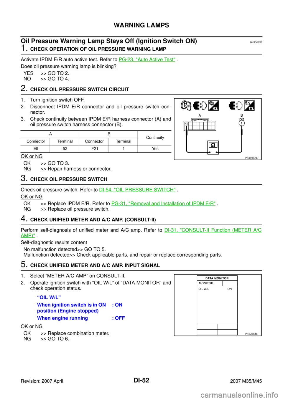
3. Check continuity between IPDM E/R harness connector (A) and
oil pressure switch harness connector (B).
OK or NG
OK >> GO TO 3.
NG >> Repair harness or connector.
3. CHECK OIL PRESSURE SWITCH
Check oil pressure switch. Refer to DI-54, "
OIL PRESSURE SWITCH" .
OK or NG
OK >> Replace IPDM E/R. Refer to PG-31, "Removal and Installation of IPDM E/R" .
NG >> Replace oil pressure switch.
4. CHECK UNIFIED METER AND A/C AMP. (CONSULT-II)
Perform self-diagnosis of unified meter and A/C amp. Refer to DI-31, "
CONSULT-II Function (METER A/C
AMP)" .
Self
-diagnostic results content
No malfunction detected>> GO TO 5.
Malfunction detected>> Check applicable parts, and repair or replace corresponding parts.
5. CHECK UNIFIED METER AND A/C AMP. INPUT SIGNAL
1. Select “METER A/C AMP” on CONSULT-II.
2. Operate ignition switch with “OIL W/L” of “DATA MONITOR” and
check operation status.
OK or NG
OK >> Replace combination meter.
NG >> GO TO 6.
AB
Continuity
Connector Terminal Connector Terminal
E9 52 F21 1 Yes
PKIB7657E
“OIL W/L”
When ignition switch is in ON
position (Engine stopped): ON
When engine running : OFF
PKIA2064E
Page 1472 of 4647

WARNING LAMPS
DI-53
C
D
E
F
G
H
I
J
L
MA
B
DI
Revision: 2007 April2007 M35/M45
6. CHECK BCM INPUT SIGNAL
1. Select “SIGNAL BUFFER” of “BCM” on CONSULT-II.
2. Operate ignition switch with “OIL PRESS SW” of “DATA MONI-
TOR” and check operate status.
OK or NG
OK >> Replace BCM. Refer to BCS-15, "Removal and Installa-
tion of BCM" .
NG >> Replace IPDM E/R. Refer to PG-31, "
Removal and Installation of IPDM E/R" .
Oil Pressure Warning Lamp Does Not Turn Off (Oil Pressure Is Normal)NKS003UT
NOTE:
For oil pressure inspection, refer to LU-8, "
OIL PRESSURE CHECK" (VQ35DE) or LU-27, "OIL PRESSURE
CHECK" (VK45DE).
1. CHECK OPERATION OF OIL PRESSURE WARNING LAMP
Activate IPDM E/R auto active test. Refer to PG-23, "
Auto Active Test" .
Does oil pressure warning lamp is blinking?
YES >> GO TO 2.
NO >> GO TO 5.
2. CHECK IPDM E/R OUTPUT SIGNAL
1. Turn ignition switch OFF.
2. Disconnect oil pressure switch connector.
3. Turn ignition switch ON.
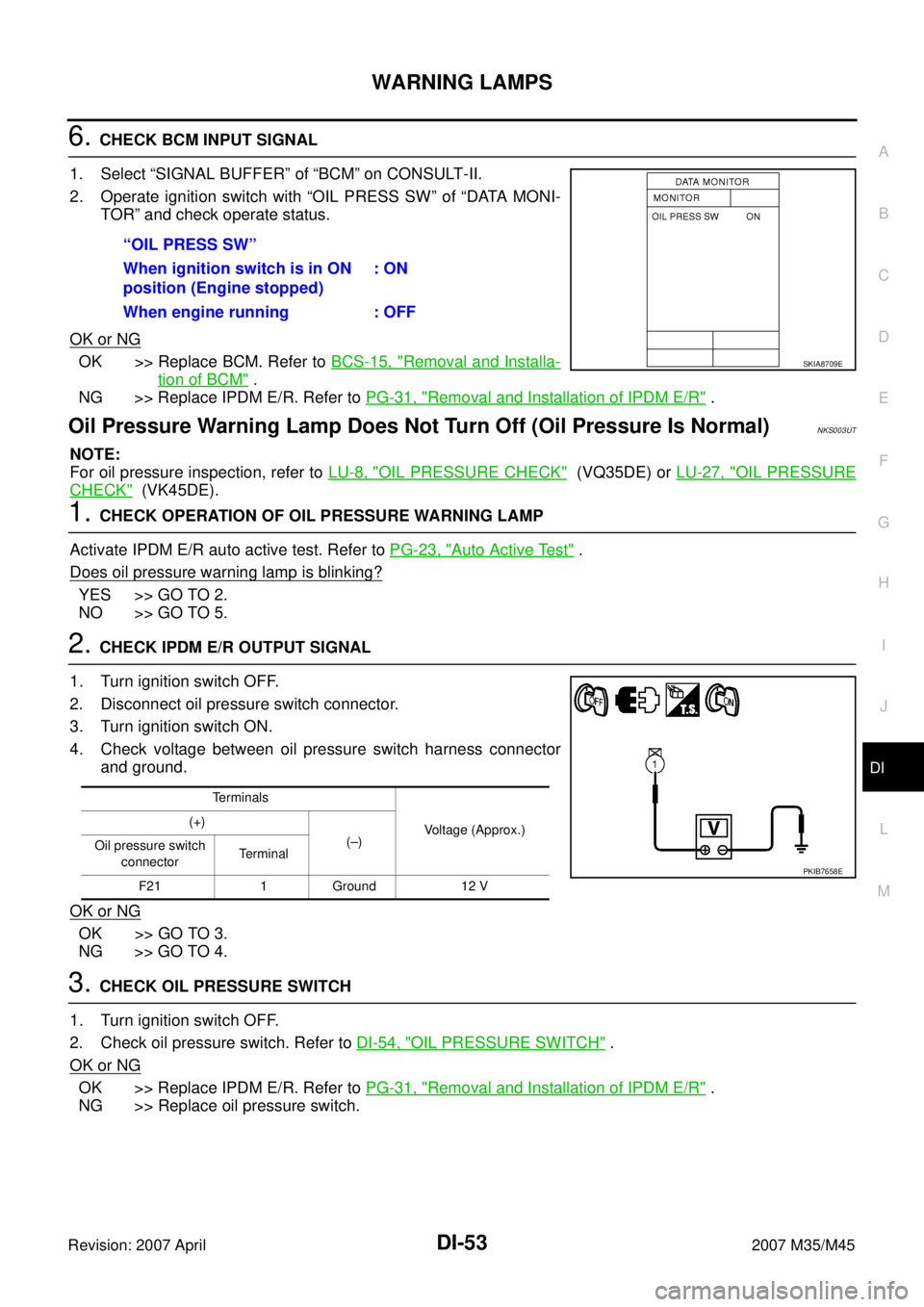
4. Check voltage between oil pressure switch harness connector
and ground.
OK or NG
OK >> GO TO 3.
NG >> GO TO 4.
3. CHECK OIL PRESSURE SWITCH
1. Turn ignition switch OFF.
2. Check oil pressure switch. Refer to DI-54, "
OIL PRESSURE SWITCH" .
OK or NG
OK >> Replace IPDM E/R. Refer to PG-31, "Removal and Installation of IPDM E/R" .
NG >> Replace oil pressure switch.“OIL PRESS SW”
When ignition switch is in ON
position (Engine stopped): ON
When engine running : OFF
SKIA8709E
Terminals
Voltage (Approx.) (+)
(–)
Oil pressure switch
connectorTerminal
F21 1 Ground 12 V
PKIB7658E
Page 1473 of 4647
DI-54
WARNING LAMPS
Revision: 2007 April2007 M35/M45
4. CHECK OIL PRESSURE SWITCH CIRCUIT
1. Turn ignition switch OFF.
2. Disconnect IPDM E/R connector.
3. Check continuity between IPDM E/R harness connector and
ground.
OK or NG
OK >> Replace IPDM E/R. Refer to PG-31, "Removal and
Installation of IPDM E/R" .
NG >> Repair harness or connector.
5. CHECK IPDM E/R (CONSULT-II)
Perform self-diagnosis of IPDM E/R. Refer to PG-20, "
CONSULT-II Function (IPDM E/R)" .
Self
-diagnostic results content
No malfunction detected>> Replace combination meter.
Malfunction detected>> Check applicable parts, and repair or replace corresponding parts.
Electrical Component InspectionNKS003UU
OIL PRESSURE SWITCH
Check continuity between oil pressure switch and ground.
IPDM E/R connector Terminal
GroundContinuity
E9 52 No
PKIB7659E
Condition
Oil pressure [kPa (kg/cm2 , psi)]Continuity
Engine stopped Less than 29 (0.3, 4) Yes
Engine running More than 29 (0.3, 4) No
ELF0044D
Page 1497 of 4647
DI-78
LANE DEPARTURE WARNING SYSTEM
Revision: 2007 April2007 M35/M45
Camera Aiming AdjustmentNKS003VI
OUTLINE
Adjust the camera aiming every time the LDW camera unit is removed or installed.
CAUTION:
�Place the vehicle on the level ground when the camera aiming adjustment is operated.
�Follow the CONSULT-II when adjusting the camera aiming. (Camera aiming adjustment cannot be
operated without CONSULT-II.)
PREPARATION
�Keep all tires inflated to correct pressures. Adjust the tire pressure to the specified pressure value.
�There is no-load in vehicle. Check if coolant, engine oil are filled up to correct level and fuel tank is full.
�Shift the gear into “P” position and release the parking brake.
�Clean the windshield.
NOTE:
Do not place anything reflective on the upper surface of instrument panel.
TARGET SETTING
Preparation Aiming Adjustment Jig
For aiming adjustment, prepare the following jigs and targets.
PKIB4693E
Page 1628 of 4647
![INFINITI M35 2007 Factory Service Manual TROUBLE DIAGNOSIS
EC-99
[VQ35DE]
C
D
E
F
G
H
I
J
K
L
MA
EC
Revision: 2007 April2007 M35/M45
Symptom Matrix ChartNBS004T1
SYSTEM — BASIC ENGINE CONTROL SYSTEM
SYMPTOM
Reference
page
HARD/NO START/RE INFINITI M35 2007 Factory Service Manual TROUBLE DIAGNOSIS
EC-99
[VQ35DE]
C
D
E
F
G
H
I
J
K
L
MA
EC
Revision: 2007 April2007 M35/M45
Symptom Matrix ChartNBS004T1
SYSTEM — BASIC ENGINE CONTROL SYSTEM
SYMPTOM
Reference
page
HARD/NO START/RE](/manual-img/42/57024/w960_57024-1627.png)
TROUBLE DIAGNOSIS
EC-99
[VQ35DE]
C
D
E
F
G
H
I
J
K
L
MA
EC
Revision: 2007 April2007 M35/M45
Symptom Matrix ChartNBS004T1
SYSTEM — BASIC ENGINE CONTROL SYSTEM
SYMPTOM
Reference
page
HARD/NO START/RESTART (EXCP. HA)
ENGINE STALL
HESITATION/SURGING/FLAT SPOT
SPARK KNOCK/DETONATION
LACK OF POWER/POOR ACCELERATION
HIGH IDLE/LOW IDLE
ROUGH IDLE/HUNTING
IDLING VIBRATION
SLOW/NO RETURN TO IDLE
OVERHEATS/WATER TEMPERATURE HIGH
EXCESSIVE FUEL CONSUMPTION
EXCESSIVE OIL CONSUMPTION
BATTERY DEAD (UNDER CHARGE)
Warranty symptom code AA AB AC AD AE AF AG AH AJ AK AL AM HA
Fuel Fuel pump circuit 11232 22 3 2EC-675
Fuel pressure regulator system334444444 4EC-88
Fuel injector circuit 11232 22 2EC-669
Evaporative emission system334444444 4EC-39
Air Positive crankcase ventilation sys-
tem
334444444 41EC-51
Incorrect idle speed adjustment 1 1 1 1 1EC-78
Electric throttle control actuator 112332222 2 2EC-
604,EC-
598 ,EC-
610 ,EC-
615
IgnitionIncorrect ignition timing adjustment33111 11 1EC-78
Ignition circuit 11222 22 2EC-691
Main power supply and ground circuit22333 33 23EC-154
Mass air flow sensor circuit
1
122
222 2EC-193,
EC-202
Engine coolant temperature sensor circuit
333EC-214,
EC-226
Air fuel ratio (A/F) sensor 1 circuitEC-234
,
EC-244
,
EC-253
,
EC-262
,
EC-646
Throttle position sensor circuit
22EC-219
,
EC-342
,
EC-518
,
EC-520
,
EC-631
Accelerator pedal position sensor circuit 3 2 1EC-
617,EC-
624 ,EC-
638 ,EC-
486
Knock sensor circuit 2 3EC-359
Crankshaft position sensor (POS) circuit 2 2EC-364
Page 1629 of 4647
![INFINITI M35 2007 Factory Service Manual EC-100
[VQ35DE]
TROUBLE DIAGNOSIS
Revision: 2007 April2007 M35/M45
1 - 6: The numbers refer to the order of inspection.
(continued on next page)Camshaft position sensor (PHASE) circuit 3 2EC-371
Vehic INFINITI M35 2007 Factory Service Manual EC-100
[VQ35DE]
TROUBLE DIAGNOSIS
Revision: 2007 April2007 M35/M45
1 - 6: The numbers refer to the order of inspection.
(continued on next page)Camshaft position sensor (PHASE) circuit 3 2EC-371
Vehic](/manual-img/42/57024/w960_57024-1628.png)
EC-100
[VQ35DE]
TROUBLE DIAGNOSIS
Revision: 2007 April2007 M35/M45
1 - 6: The numbers refer to the order of inspection.
(continued on next page)Camshaft position sensor (PHASE) circuit 3 2EC-371
Vehicle speed signal circuit 2 3 3 3EC-468
Power steering pressure sensor circuit 2 3 3EC-474
ECM 22333333333EC-479,
EC-483
Intake valve timing control solenoid valve cir-
cuit32 13223 3EC-185
PNP switch circuit 3 3 3 3 3EC-491
Refrigerant pressure sensor circuit 2 3 3 4EC-704
Electrical load signal circuit 3EC-667
Air conditioner circuit 223333333 3 2AT C - 4 0
ABS actuator and electric unit (control unit) 4BRC-10
SYMPTOM
Reference
page
HARD/NO START/RESTART (EXCP. HA)
ENGINE STALL
HESITATION/SURGING/FLAT SPOT
SPARK KNOCK/DETONATION
LACK OF POWER/POOR ACCELERATION
HIGH IDLE/LOW IDLE
ROUGH IDLE/HUNTING
IDLING VIBRATION
SLOW/NO RETURN TO IDLE
OVERHEATS/WATER TEMPERATURE HIGH
EXCESSIVE FUEL CONSUMPTION
EXCESSIVE OIL CONSUMPTION
BATTERY DEAD (UNDER CHARGE)
Warranty symptom code AA AB AC AD AE AF AG AH AJ AK AL AM HA