Page 4529 of 4647
TF-40
FRONT OIL SEAL
Revision: 2007 April2007 M35/M45
FRONT OIL SEALPFP:38189
Removal and InstallationNDS000E1
REMOVAL
1. Remove the drain plug to drain the transfer fluid. Refer to TF-9, "Replacement" .
2. Remove the front propeller shaft. Refer to PR-4, "
FRONT PROPELLER SHAFT" .
3. Remove front oil seal using a flat-bladed screwdriver.
CAUTION:
Be careful not to damage the front case and front drive
shaft.
INSTALLATION
1. Apply ATF to front oil seal, install it with a drift until the end face
of front case.
CAUTION:
�Do not reuse front oil seal.
�When installing, do not incline front oil seal.
2. Install front propeller shaft. Refer to PR-4, "
FRONT PROPEL-
LER SHAFT" .
3. Install transfer fluid, check fluid level and for fluid leakage. Refer
to TF-9, "
Inspection" .
SDIA1782E
Tool number : ST27862000 ( — )
SDIA1783E
Page 4530 of 4647
REAR OIL SEAL
TF-41
C
E
F
G
H
I
J
K
L
MA
B
TF
Revision: 2007 April2007 M35/M45
REAR OIL SEALPFP:33140
Removal and InstallationNDS000E2
REMOVAL
1. Remove the rear propeller shaft. Refer to PR-6, "REAR PROPELLER SHAFT" .
2. Remove self-lock nut of companion flange using a flange
wrench.
3. Put matching mark on the end of the mainshaft. The mark
should be in line with the mark on the companion flange.
CAUTION:
For matching mark, use paint. Do not damage mainshaft.
4. Remove the companion flange using a puller.
CAUTION:
Be careful not to damage the companion flange.
5. Remove the rear oil seal using the puller.
CAUTION:
Be careful not to damage the rear case.
SDIA2454E
SDIA2378E
SDIA1785E
Tool number : KV381054S0 (J-34286)
SDIA1786E
Page 4531 of 4647
TF-42
REAR OIL SEAL
Revision: 2007 April2007 M35/M45
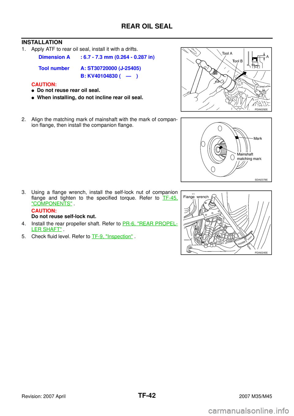
INSTALLATION
1. Apply ATF to rear oil seal, install it with a drifts.
CAUTION:
�Do not reuse rear oil seal.
�When installing, do not incline rear oil seal.
2. Align the matching mark of mainshaft with the mark of compan-
ion flange, then install the companion flange.
3. Using a flange wrench, install the self-lock nut of companion
flange and tighten to the specified torque. Refer to TF-45,
"COMPONENTS" .
CAUTION:
Do not reuse self-lock nut.
4. Install the rear propeller shaft. Refer to PR-6, "
REAR PROPEL-
LER SHAFT" .
5. Check fluid level. Refer to TF-9, "
Inspection" . Dimension A : 6.7 - 7.3 mm (0.264 - 0.287 in)
Tool number A: ST30720000 (J-25405)
B: KV40104830 ( — )
PDIA0292E
SDIA2378E
PDIA0245E
Page 4533 of 4647

TF-44
TRANSFER ASSEMBLY
Revision: 2007 April2007 M35/M45
TRANSFER ASSEMBLYPFP:33100
Removal and InstallationNDS000E4
REMOVAL
1. Remove exhaust front tube with power tool. Refer to EX-3, "EXHAUST SYSTEM" .
2. Remove front and rear propeller shaft. Refer to PR-4, "
FRONT PROPELLER SHAFT" and PR-6, "REAR
PROPELLER SHAFT" .
3. Disconnect transfer assembly harness connector and separate harness from transfer assembly.
4. Remove air breather hose. Refer to TF-43, "
AIR BREATHER HOSE" .
5. Remove control rod. Refer to AT- 2 2 6 , "
Control Rod Removal and Installation" .
6. Support transfer assembly and transmission assembly with a jack.
7. Remove rear engine mounting member and engine mounting insulator with power tool. Refer to EM-114,
"ENGINE ASSEMBLY" .
8. Lower jack to the position where the top transfer mounting bolts
can be removed.
9. Remove transfer mounting bolts with power tool and separate
transfer from transmission.
CAUTION:
Secure transfer assembly and transmission assembly to a
jack.
INSTALLATION
Note the following, and install in the reverse order of removal.
�When installing the transfer to the transmission, install the
mounting bolts following the standard below.
�After the installation, check the fluid level, fluid leakage and the
A/T positions. Refer to TF-9, "
Inspection" ,AT- 2 2 7 , "Adjustment
of A/T Position" .
PDIA0560J
Bolt No. 1 2 3 4
Quantity 4 3 2 1
Bolt length “ ” mm (in)75 (2.95) 45 (1.77) 40 (1.57) 30 (1.18)
Tightening torque
N·m (kg-m, ft-lb)37 (3.8, 27)
SDIA2284E
Page 4554 of 4647
 TROUBLESHOOTING
WT-5
C
D
F
G
H
I
J
K
L
MA
B
WT
Revision: 2007 April2007 M35/M45
NOISE, VIBRATION AND HARSHNESS (NVH) TROUBLESHOOTINGPFP:00003
NVH Troubleshooting C")
NOISE, VIBRATION AND HARSHNESS (NVH) TROUBLESHOOTING
WT-5
C
D
F
G
H
I
J
K
L
MA
B
WT
Revision: 2007 April2007 M35/M45
NOISE, VIBRATION AND HARSHNESS (NVH) TROUBLESHOOTINGPFP:00003
NVH Troubleshooting ChartNES000JN
Use chart below to help you find the cause of the symptom. If necessary, repair or replace these parts.
×: ApplicableReference page
FAX-5
, RAX-5WT-6WT-7WT-41WT-8—
—
WT-41
NVH in PR section.
NVH in FFD and RFD section.
NVH in FAX and FSU sections.
NVH in RAX and RSU sections.
Refer to TIRES in this chart.
Refer to ROAD WHEEL in this chart.
NVH in FAX, RAX section.
NVH in BR section.
NVH in PS section.
Possible cause and SUSPECTED PARTS
Improper installation, looseness
Out-of-round
Unbalance
Incorrect tire pressure
Uneven tire wear
Deformation or damage
Non-uniformity
Incorrect tire size
PROPELLER SHAFT
DIFFERENTIAL
FRONT AXLE AND FRONT SUSPENSION
REAR AXLE AND REAR SUSPENSION
TIRES
ROAD WHEELS
DRIVE SHAFT
BRAKE
STEERING
SymptomTIRESNoise××××××× ×××× ××××
Shake×××××× ×× ×× ××××
Vibration×××××××
Shimmy×××××××× ×× × ××
Judder×××××× × ×× × ××
Poor quality ride or
handling×××××× × × ××
ROAD
WHEELNoise××× × ××××× ×××
Shake××× × × ××× ×××
Shimmy, Judder××× × ××× ××
Poor quality ride or
handling××× × ×××