Page 4000 of 4647

POWER STEERING GEAR AND LINKAGE
PS-19
C
D
E
F
H
I
J
K
L
MA
B
PS
Revision: 2007 April2007 M35/M45
POWER STEERING GEAR AND LINKAGEPFP:49001
Removal and InstallationNGS000DC
COMPONENTS
CAUTION:
Spiral cable may be cut if steering wheel turns while separating steering column assembly and steer-
ing gear assembly. Be sure to secure steering wheel using string to avoid turning.
REMOVAL
1. Set vehicle to the straight-ahead position.
2. Remove tires from vehicle with a power tool.
3. Remove undercover from vehicle with a power tool.
4. Remove lower side fixing bolt of lower joint.
5. Remove cotter pin (1), and then loosen the nut.
6. Remove steering outer socket (2) from steering knuckle (3) so
as not to damage ball joint boot (4) using the ball joint remover
(suitable tool).
CAUTION:
Temporarily tighten the nut to prevent damage to threads
and to prevent the ball joint remover from suddenly coming
off.
7. Remove high and low pressure piping of hydraulic piping, and
then drain power steering fluid. Refer to PS-39, "
HYDRAULIC
LINE" .
1. Cotter pin 2. Steering gear assembly 3. Steering gear assembly
(AWD models)
Refer to GI-11, "
Components" , for the symbols in the figure.
SGIA1387E
SGIA0844E
SGIA1183E
Page 4002 of 4647

POWER STEERING GEAR AND LINKAGE
PS-21
C
D
E
F
H
I
J
K
L
MA
B
PS
Revision: 2007 April2007 M35/M45
Disassembly and AssemblyNGS000DD
COMPONENTS
CAUTION:
�Disassemble and assemble steering gear assembly by securing the mounting area in a vise using
copper plates.
�Clean steering gear assembly with kerosene before disassembling. Be careful to avoid splashing
or applying any kerosene over connector of discharge port or return port.
1. Outer socket 2. Boot clamp 3. Boot
4. Inner socket 5. Boot clamp (stainless wire) 6. End cover assembly
7. Rack oil seal 8. Rack Teflon ring 9. O-ring
10. Rack assembly 11. Gear housing assembly 12. Cylinder tubes
13. O-ring 14. Gear-sub assembly 15. power steering solenoid valve
16. Rear cover cap
Refer to GI-11, "
Components" , and the followings for the symbols in the figure.
: Apply power steering fluid.
: A p p l y G e n u i n e L i q u i d G a s k e t , T h r e e B o n d 1111 B o r e q u i v a l e n t .
: Apply multi-purpose grease.
SGIA1388E
Page 4003 of 4647

PS-22
POWER STEERING GEAR AND LINKAGE
Revision: 2007 April2007 M35/M45
DISASSEMBLY
1. Remove fixing bolts of power steering solenoid valve, and then remove power steering solenoid valve
from gear-sub assembly.
2. Remove cylinder tubes from gear housing assembly.
3. Remove rear cover cap from gear-sub assembly.
4. Measure adjusting screw height “H”, and loosen adjusting
screw.
CAUTION:
�Do not loosen adjusting screw 2 turns or more.
�Replace steering gear assembly if adjusting screw is
loosened 2 turns or more and it is removed.
5. Remove fixing bolts of gear-sub assembly, and then remove
gear-sub assembly from gear housing assembly.
6. Remove O-ring from gear housing assembly.
7. Loosen outer socket lock nut, and remove outer socket.
8. Remove boot clamp, and then remove boot from inner socket.
CAUTION:
Do not damage inner socket and gear housing assembly when removing boot. Inner socket and
gear housing assembly must be replaced if inner socket and gear housing assembly are damaged
because it may cause foreign material interfusion.
9. Remove inner socket from gear housing assembly.
10. Drill out the clinching part of gear housing assembly (end cover
assembly side) outer rim with a 3 mm (0.12 in) drill bit. [Drill for
approximately 1.5 mm (0.059 in) depth.]
11. Remove end cover assembly with a 36 mm (1.42 in) open head
(suitable tool).
CAUTION:
Do not damage rack assembly surface when removing.
Rack assembly must be replaced if damaged because it
may cause fluid leakage.
12. Pull rack assembly together with rack oil seal (outer side) out
from gear housing assembly.
CAUTION:
Do not damage cylinder inner wall when removing rack
assembly. Gear housing assembly must be replaced if dam-
aged because it may cause fluid leakage.
13. Heat rack Teflon ring to approximately 40°C (104°F) with a
dryer, and remove rack Teflon ring and O-ring from rack assem-
bly.
CAUTION:
Do not damage rack assembly. Rack assembly must be
replaced if damaged because it may cause fluid leakage.
SGIA0624E
STC0013D
SST081B
SGIA0151E
Page 4004 of 4647
POWER STEERING GEAR AND LINKAGE
PS-23
C
D
E
F
H
I
J
K
L
MA
B
PS
Revision: 2007 April2007 M35/M45
14. Push rack oil seal inside with a 29 mm (1.14 in) socket and an
extension bar to push out rack oil seal (inner side) from gear
housing assembly.
CAUTION:
Do not damage gear housing assembly and cylinder inner
wall. Gear housing assembly must be replaced if damaged
because it may cause fluid leakage.
INSPECTION AFTER DISASSEMBLY
Boot
Check boot for cracks, and replace it if a malfunction is detected.
Rack Assembly
Check rack for damage or wear, and replace it if a malfunction is detected.
Gear-Sub Assembly
�Check gear-sub assembly for damage or wear, and replace it if a malfunction is detected.
�Rotate gear-sub assembly and check for torque variation or rattle, and replace it if a malfunction is
detected.
Gear Housing Assembly
Check gear housing assembly for damage and scratches (inner wall). Replace if there are.
SGIA0179E
Page 4009 of 4647

PS-28
POWER STEERING GEAR AND LINKAGE
Revision: 2007 April2007 M35/M45
19. Install large end of boot to gear housing assembly.
20. Install small end of boot to inner socket boot mounting groove.
21. Install boot clamp to boot small end.
22. Install large side of boot clamp.
�Tighten large side of boot with boot clamp (stainless wire).
�Wrap clamp around boot groove for two turns. Insert a flat-
bladed screwdriver in loops on both ends of wire. Twist 4 to
4.5 turns while pulling them with force of approximately 98 N
(10 kg, 22 lb).
�Twist boot clamp as shown. Pay attention to relationship
between winding and twisting directions.
�Twisted point of clamp is in the opposite side of adjusting
screw (1) as shown in the figure (to prevent contact with other
parts).
Measuring pointRack axial direction 5 mm (0.20 in) from housing end surface
Rack radial direction Axial direction of the adjusting screw
Vertical movement of rack 0.265 mm (0.0104 in)
SGIA1325E
Wire length L : 370 mm (14.57 in)
SGIA0163E
SGIA0164E
SGIA1186E
Page 4010 of 4647
POWER STEERING GEAR AND LINKAGE
PS-29
C
D
E
F
H
I
J
K
L
MA
B
PS
Revision: 2007 April2007 M35/M45
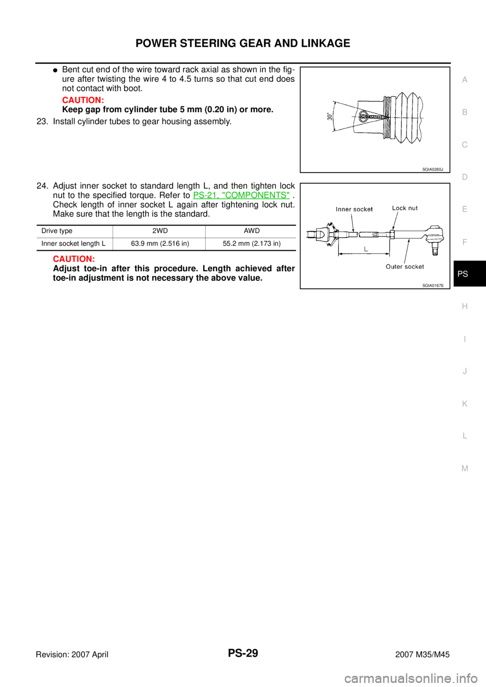
�Bent cut end of the wire toward rack axial as shown in the fig-
ure after twisting the wire 4 to 4.5 turns so that cut end does
not contact with boot.
CAUTION:
Keep gap from cylinder tube 5 mm (0.20 in) or more.
23. Install cylinder tubes to gear housing assembly.
24. Adjust inner socket to standard length L, and then tighten lock
nut to the specified torque. Refer to PS-21, "
COMPONENTS" .
Check length of inner socket L again after tightening lock nut.
Make sure that the length is the standard.
CAUTION:
Adjust toe-in after this procedure. Length achieved after
toe-in adjustment is not necessary the above value.
SGIA0260J
Drive type 2WD AWD
Inner socket length L 63.9 mm (2.516 in) 55.2 mm (2.173 in)
SGIA0167E
Page 4033 of 4647
 and
wood block, and then remov")
RAX-6
WHEEL HUB
Revision: 2007 April2007 M35/M45
5. Separate the wheel hub and bearing assembly from drive shaft
by lightly tapping the end with a hammer (suitable tool) and
wood block, and then remove hub lock nut.
CAUTION:
�Do not place drive shaft joint at an extreme angle. Also be
careful not to overextend slide joint.
�Do not allow drive shaft to hang down without support for
housing (or joint sub-assembly), shaft and other parts.
NOTE:
Use a puller (suitable tool), if the wheel hub and bearing assem-
bly and drive shaft cannot be separated even after performing
the above procedure.
6. Remove the wheel hub and bearing assembly mounting bolts.
7. Remove the wheel hub and bearing assembly.
Axle Housing
1. Refer to the procedure from 1 to 5 in “Wheel Hub and Bearing Assembly”. RAX-5, "REMOVAL" .
2. Remove parking brake shoe and parking brake cable from back plate. Refer to PB-6, "
PARKING BRAKE
SHOE" , Refer to PB-4, "PARKING BRAKE CONTROL" .
3. Remove coil spring. Refer to RSU-16, "
REAR LOWER LINK & COIL SPRING" .
4. Remove mounting bolt and nut in axle side of shock absorber with a power tool.
5. Remove axle side nuts and bolts on radius rod and front lower link with a power tool. Refer to RSU-14,
"RADIUS ROD" , RSU-15, "FRONT LOWER LINK" .
6. Remove cotter pin, then loosen suspension arm mounting nut of axle housing.
7. Remove suspension arm from axle housing so as not to damage ball joint boot using ball joint remover
(suitable tool), and then remove axle housing from the vehicle.
CAUTION:
�Temporarily tighten nuts to prevent damage to threads and to prevent ball joint remover (suit-
able tool) from coming off.
�Do not place drive shaft joint at an extreme angle. Also be careful not to overextend slide joint.
�Do not allow drive shaft to hang down without support for counterpart such as joint sub-assem-
bly, and other parts.
8. Remove the wheel hub and bearing assembly from axle housing.
9. Remove anchor block mounting nuts, and then remove anchor block and back plate from axle housing.
INSPECTION AFTER REMOVAL
Wheel Hub and Bearing Assembly
Check the wheel hub and bearing assembly for wear, cracks, and damage. Replace if there are.
Axle Housing
Check axle housing for wear, cracks, and damage. Replace if there are.
Ball Joint Inspection
Check for boot breakage, axial looseness, and torque of suspension arm ball joint. Refer to RSU-12, "SUS-
PENSION ARM" .
INSTALLATION
Wheel Hub and Bearing Assembly
�Installation is the reverse order of removal. For tightening torque refer to RAX-5, "COMPONENT" .
CAUTION:
Do not reuse non-reusable parts.
SDIA1821E
Page 4036 of 4647

REAR DRIVE SHAFT
RAX-9
C
E
F
G
H
I
J
K
L
MA
B
RAX
Revision: 2007 April2007 M35/M45
�Check boot for cracks or other damage, and also for grease
leakage.
�If a malfunction is found, disassemble drive shaft, and then
replace with new one.
INSTALLATION
Installation is the reverse order of removal. For tightening torque. Refer to RAX-8, "COMPONENT" .
CAUTION:
Do not reuse non-reusable parts.
Disassembly and AssemblyNDS000FT
COMPONENT
DISASSEMBLY
Final Drive Side
1. Place shaft in a vise.
CAUTION:
When retaining shaft in a vise, always use copper or aluminum plates between vise and shaft.
2. Remove boot bands, and then remove boot from housing.
3. If plug needs to be removed, move boot to wheel side, and take it out with a plastic hammer.
4. Put matching marks on housing and shaft.
CAUTION:
Use paint or similar substance for matching marks. Do not scratch the surface.
RAA0030D
1. Plug 2. Housing 3. Snap ring
4. Ball cage, steel ball and Inner race
assembly5. Stopper ring 6. Boot band
7. Boot 8. Shaft 9. Circular clip
10. Joint sub-assembly 11. Dust shield
Refer to GI-11, "
Components" and the followings for symbols in the figure.
: NISSAN genuine grease or equivalent
SDIA3029J
 socket and an
extension bar to push out rack oil s")