Page 3970 of 4647
NOISE, VIBRATION AND HARSHNESS (NVH) TROUBLESHOOTING
PR-3
C
E
F
G
H
I
J
K
L
MA
B
PR
Revision: 2007 April2007 M35/M45
NOISE, VIBRATION AND HARSHNESS (NVH) TROUBLESHOOTINGPFP:00003
NVH Troubleshooting ChartNDS000E9
Use the chart below to help you find the cause of the symptom. If necessary, repair or replace these parts.
×: Applicable Reference pageFront
PR-4—
—
—
—
PR-4PR-5
NVH in FFD and RFD section
NVH in FAX, RAX, FSU and RSU section
NVH in WT section
NVH in WT section
NVH in RAX section
NVH in BR section
NVH in PS section
RearPR-6PR-10—
PR-7—
PR-6PR-9
Possible cause and SUSPECTED PARTS
Uneven rotating torque
Center bearing improper installation
Excessive center bearing axial end play
Center bearing mounting (insulator) cracks, damage or deterioration
Excessive joint angle
Rotation imbalance
Excessive runout
DIFFERENTIAL
AXLE AND SUSPENSION
TIRES
ROAD WHEEL
DRIVE SHAFT
BRAKES
STEERING
SymptomNoise××××××××××××××
Shake× × ××××××
Vibration××××××× ×× × ×
Page 3986 of 4647
PREPARATION
PS-5
C
D
E
F
H
I
J
K
L
MA
B
PS
Revision: 2007 April2007 M35/M45
PREPARATIONPFP:00002
Special Service ToolsNGS000D2
The actual shapes of Kent-Moore tools may differ from those of special service tools illustrated here.
Tool number
(Kent-Moore No.)
Tool nameDescription
ST27180001
(J-25726-A)
Steering wheel pullerRemoving steering wheel
ST3127S000
(See J-25765-A)
Preload gauge
1. GG9103000
(J-25765-A)
Torque wrench
2. HT62940000
(–)
Socket adapter
3. HT62900000
(–)
Socket adapterInspecting sliding torque, steering torque, and
rotating torque for ball joint
KV48104400
(–)
Teflon ring correcting tool
a: 50 mm (1.97 in) dia.
b: 36 mm (1.42 in) dia.
c: 100 mm (3.94 in)Installing rack Teflon ring
KV48103400
(–)
Preload adapterInspecting rotating torque
KV48103500
(J-26357)
Oil pressure gaugeMeasuring oil pump relief pressure
S-NT544
S-NT541
S-NT550
ZZA0824D
S-NT547
Page 3988 of 4647
 TROUBLESHOOTING
PS-7
C
D
E
F
H
I
J
K
L
MA
B
PS
Revision: 2007 April2007 M35/M45
NOISE, VIBRATION AND HARSHNESS (NVH) TROUBLESHOOTINGPFP:00003
NVH Trouble Shooting")
NOISE, VIBRATION AND HARSHNESS (NVH) TROUBLESHOOTING
PS-7
C
D
E
F
H
I
J
K
L
MA
B
PS
Revision: 2007 April2007 M35/M45
NOISE, VIBRATION AND HARSHNESS (NVH) TROUBLESHOOTINGPFP:00003
NVH Trouble Shooting ChartNGS000D4
Use chart below to help you find the cause of the symptom. If necessary, repair or replace these parts.
×: ApplicableReference page
PS-8PS-8PS-24PS-24PS-24PS-8PS-10PS-10
EM-16
,EM-174PS-10—
PS-23PS-16PS-13PS-21
NVH in PR section
NVH in RFD section
NVH in FAX, RAX, FSU, RSU section
NVH in WT section
NVH in WT section
NVH in FAX section
NVH in BR section
Possible cause and SUSPECTED PARTS
Fluid level
Air in hydraulic system
Outer socket ball joint swinging torque
Outer socket ball joint rotating torque
Outer socket ball joint end play
Steering fluid leakage
Steering wheel play
Steering gear rack sliding force
Drive belt looseness
Improper steering wheel
Improper installation or looseness of tilt lock lever
Mounting rubber deterioration
Steering column deformation or damage
Improper installation or looseness of steering column
Steering linkage looseness
PROPELLER SHAFT
DIFFERENTIAL
AXLE and SUSPENSION
TIRES
ROAD WHEEL
DRIVE SHAFT
BRAKES
Symptom SteeringNoise× × ××××× × × ×××××× ×
Shake×× ××××××
Vibration×××× ××××
Shimmy× × × ××× ×
Judder× × ××× ×
Page 3993 of 4647
PS-12
STEERING WHEEL
Revision: 2007 April2007 M35/M45
Removal and InstallationNGS000D9
REMOVAL
NOTE:
When reconnecting spiral cable, fix cable with a tape so that fixing case and rotating part keep aligned. This
will omit neutral position alignment procedure during spiral cable installation.
1. Set vehicle to the straight-ahead position.
2. Remove driver air bag module. Refer to SRS-42, "
DRIVER AIR BAG MODULE" .
3. Remove steering wheel lock nut after steering is locked.
4. Remove steering wheel with the steering wheel puller [SST].
INSTALLATION
Installation is the reverse order of removal. For tightening torque, refer to PS-13, "COMPONENTS" .
NOTE:
Check the spiral cable neutral position after replacing or rotating spiral cable. Refer to SRS-44, "
INSTALLA-
TION" .
CAUTION:
Do not twist spiral cable freely on excessively after it becomes tight (doing so may cause the cable to
be turn off).
SGIA0939E
Page 3997 of 4647

PS-16
STEERING COLUMN
Revision: 2007 April2007 M35/M45
INSPECTION AFTER REMOVAL
�Check each part of steering column assembly for damage or other malfunctions. Replace if there are.
�Measure the length L as shown in the figure if vehicle has been
involved in a minor collision. Replace steering column assembly
if outside the standard.
�Measure steering column assembly rotating torque using preload gauge [SST: ST3127S000]. Replace
steering column assembly if outside the standard.
INSTALLATION OF STEERING COLUMN ASSEMBLY
�Installation is the reverse order of removal. For tightening torque, refer to PS-13, "COMPONENTS" .
�When installing upper joint, the angle which upper joint yoke (1)
forms with shaft center groove (A) should be at 90°.
�Adjust neutral position of steering angle sensor. Refer to BRC-6,
"Adjustment of Steering Angle Sensor Neutral Position" .
INSPECTION AFTER INSTALLATION
Make sure that steering wheel operates smoothly by turning several times from full left stop to full right stop.
SGIA1177E
Steering column length LTelescopic maximum 551 – 555 mm (21.69 – 21.85 in)
Telescopic minimum 591 – 595 mm (23.27 – 23.43 in)
Rotating torque : 0 – 0.2 N·m (0 – 0.02 kg-m, 0 – 1 in-lb)
SGIA1290E
Page 4001 of 4647

PS-20
POWER STEERING GEAR AND LINKAGE
Revision: 2007 April2007 M35/M45
8. Remove steering hydraulic piping bracket from front suspension member. Refer to PS-39, "HYDRAULIC
LINE" .
9. Remove power steering solenoid valve harness connector. Refer to PS-21, "
COMPONENTS" .
10. Remove rack stay (2WD) or front cross bar (AWD). Refer to FSU-8, "
Components" , FSU-26, "Compo-
nents" .
11. Remove mounting bolts and nuts of steering gear assembly, and then remove steering gear assembly
from vehicle.
INSTALLATION
Installation is the reverse order of removal. For tightening torque, refer to PS-19, "COMPONENTS" .
�When installing lower joint to steering gear assembly, follow the procedure listed below.
–Set rack of steering gear in the neutral position.
NOTE:
To get the neutral position of rack, turn gear-sub assembly and measure the distance of inner socket, and
then measure the intermediate position of the distance.
–Align rear cover cap projection (A) with the marking position (B)
of gear housing assembly.
–Install slit part of lower joint (C) aligning with the projection (A) of
rear cover cap (1). Make sure that the slit part of lower joint (C)
is aligned with both the projection (A) of rear cover cap (1) and
the marking position (B) of gear housing assembly.
�After installation, bleed air from the steering hydraulic system.
Refer to PS-8, "
Air Bleeding Hydraulic System" .
�Perform final tightening of nuts and bolts on each part under
unladen conditions with tires on level ground when removing
steering gear assembly. Check wheel alignment. Refer to FSU-
6, "Wheel Alignment Inspection" , FSU-24, "Wheel Alignment
Inspection" .
�Adjust neutral position of steering angle sensor after checking wheel alignment. Refer to BRC-6, "Adjust-
ment of Steering Angle Sensor Neutral Position" .
INSPECTION AFTER INSTALLATION
Make sure that steering wheel operates smoothly by turning several times from full left stop to full right stop.
SGIA1175E
Page 4033 of 4647
 and
wood block, and then remov")
RAX-6
WHEEL HUB
Revision: 2007 April2007 M35/M45
5. Separate the wheel hub and bearing assembly from drive shaft
by lightly tapping the end with a hammer (suitable tool) and
wood block, and then remove hub lock nut.
CAUTION:
�Do not place drive shaft joint at an extreme angle. Also be
careful not to overextend slide joint.
�Do not allow drive shaft to hang down without support for
housing (or joint sub-assembly), shaft and other parts.
NOTE:
Use a puller (suitable tool), if the wheel hub and bearing assem-
bly and drive shaft cannot be separated even after performing
the above procedure.
6. Remove the wheel hub and bearing assembly mounting bolts.
7. Remove the wheel hub and bearing assembly.
Axle Housing
1. Refer to the procedure from 1 to 5 in “Wheel Hub and Bearing Assembly”. RAX-5, "REMOVAL" .
2. Remove parking brake shoe and parking brake cable from back plate. Refer to PB-6, "
PARKING BRAKE
SHOE" , Refer to PB-4, "PARKING BRAKE CONTROL" .
3. Remove coil spring. Refer to RSU-16, "
REAR LOWER LINK & COIL SPRING" .
4. Remove mounting bolt and nut in axle side of shock absorber with a power tool.
5. Remove axle side nuts and bolts on radius rod and front lower link with a power tool. Refer to RSU-14,
"RADIUS ROD" , RSU-15, "FRONT LOWER LINK" .
6. Remove cotter pin, then loosen suspension arm mounting nut of axle housing.
7. Remove suspension arm from axle housing so as not to damage ball joint boot using ball joint remover
(suitable tool), and then remove axle housing from the vehicle.
CAUTION:
�Temporarily tighten nuts to prevent damage to threads and to prevent ball joint remover (suit-
able tool) from coming off.
�Do not place drive shaft joint at an extreme angle. Also be careful not to overextend slide joint.
�Do not allow drive shaft to hang down without support for counterpart such as joint sub-assem-
bly, and other parts.
8. Remove the wheel hub and bearing assembly from axle housing.
9. Remove anchor block mounting nuts, and then remove anchor block and back plate from axle housing.
INSPECTION AFTER REMOVAL
Wheel Hub and Bearing Assembly
Check the wheel hub and bearing assembly for wear, cracks, and damage. Replace if there are.
Axle Housing
Check axle housing for wear, cracks, and damage. Replace if there are.
Ball Joint Inspection
Check for boot breakage, axial looseness, and torque of suspension arm ball joint. Refer to RSU-12, "SUS-
PENSION ARM" .
INSTALLATION
Wheel Hub and Bearing Assembly
�Installation is the reverse order of removal. For tightening torque refer to RAX-5, "COMPONENT" .
CAUTION:
Do not reuse non-reusable parts.
SDIA1821E
Page 4034 of 4647
WHEEL HUB
RAX-7
C
E
F
G
H
I
J
K
L
MA
B
RAX
Revision: 2007 April2007 M35/M45
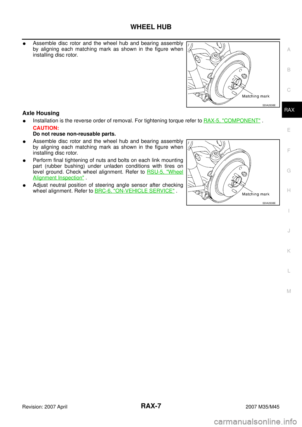
�Assemble disc rotor and the wheel hub and bearing assembly
by aligning each matching mark as shown in the figure when
installing disc rotor.
Axle Housing
�Installation is the reverse order of removal. For tightening torque refer to RAX-5, "COMPONENT" .
CAUTION:
Do not reuse non-reusable parts.
�Assemble disc rotor and the wheel hub and bearing assembly
by aligning each matching mark as shown in the figure when
installing disc rotor.
�Perform final tightening of nuts and bolts on each link mounting
part (rubber bushing) under unladen conditions with tires on
level ground. Check wheel alignment. Refer to RSU-5, "
Wheel
Alignment Inspection" .
�Adjust neutral position of steering angle sensor after checking
wheel alignment. Refer to BRC-6, "
ON-VEHICLE SERVICE" .
SDIA2638E
SDIA2638E
 TROUBLESHOOTING
PR-3
C
E
F
G
H
I
J
K
L
MA
B
PR
Revision: 2007 April2007 M35/M45
NOISE, VIBRATION AND HARSHNESS (NVH) TROUBLESHOOTINGPFP:00003
NVH Troubleshooting C")