Page 4628 of 4647
FRONT WIPER AND WASHER SYSTEM
WW-37
C
D
E
F
G
H
I
J
L
MA
B
WW
Revision: 2007 April2007 M35/M45
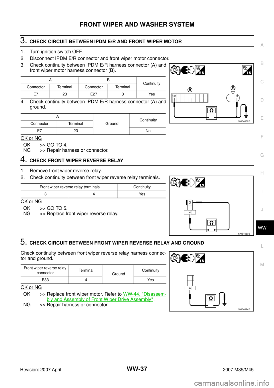
3. CHECK CIRCUIT BETWEEN IPDM E/R AND FRONT WIPER MOTOR
1. Turn ignition switch OFF.
2. Disconnect IPDM E/R connector and front wiper motor connector.
3. Check continuity between IPDM E/R harness connector (A) and
front wiper motor harness connector (B).
4. Check continuity between IPDM E/R harness connector (A) and
ground.
OK or NG
OK >> GO TO 4.
NG >> Repair harness or connector.
4. CHECK FRONT WIPER REVERSE RELAY
1. Remove front wiper reverse relay.
2. Check continuity between front wiper reverse relay terminals.
OK or NG
OK >> GO TO 5.
NG >> Replace front wiper reverse relay.
5. CHECK CIRCUIT BETWEEN FRONT WIPER REVERSE RELAY AND GROUND
Check continuity between front wiper reverse relay harness connec-
tor and ground.
OK or NG
OK >> Replace front wiper motor. Refer to WW-44, "Disassem-
bly and Assembly of Front Wiper Drive Assembly" .
NG >> Repair harness or connector.
AB
Continuity
Connector Terminal Connector Terminal
E7 23 E27 3 Yes
A
GroundContinuity
Connector Terminal
E7 23 No
SKIB4682E
Front wiper reverse relay terminals Continuity
34Yes
SKIB4660E
Front wiper reverse relay
connectorTerminal
GroundContinuity
E33 4 Yes
SKIB4674E
Page 4630 of 4647
FRONT WIPER AND WASHER SYSTEM
WW-39
C
D
E
F
G
H
I
J
L
MA
B
WW
Revision: 2007 April2007 M35/M45
4. CHECK FRONT WIPER REVERSE RELAY
Check continuity between front wiper reverse relay terminals.
OK or NG
OK >> GO TO 5.
NG >> Replace front wiper reverse relay.
5. CHECK CIRCUIT BETWEEN IPDM E/R AND FRONT WIPER MOTOR
1. Turn ignition switch OFF.
2. Disconnect IPDM E/R connector and front wiper motor connector.
3. Check continuity between IPDM E/R harness connector (A) and
front wiper motor harness connector (B).
OK or NG
OK >> GO TO 6.
NG >> Repair harness or connector.
Front wiper reverse
relay terminalsCondition Continuity
35Applying battery voltage to between
terminals 1 and 2Ye s
No battery voltage No
SKIB4671E
AB
Continuity
Connector Terminal Connector Terminal
E7 31 E27 2 Yes
SKIB4679E
Page 4631 of 4647
WW-40
FRONT WIPER AND WASHER SYSTEM
Revision: 2007 April2007 M35/M45
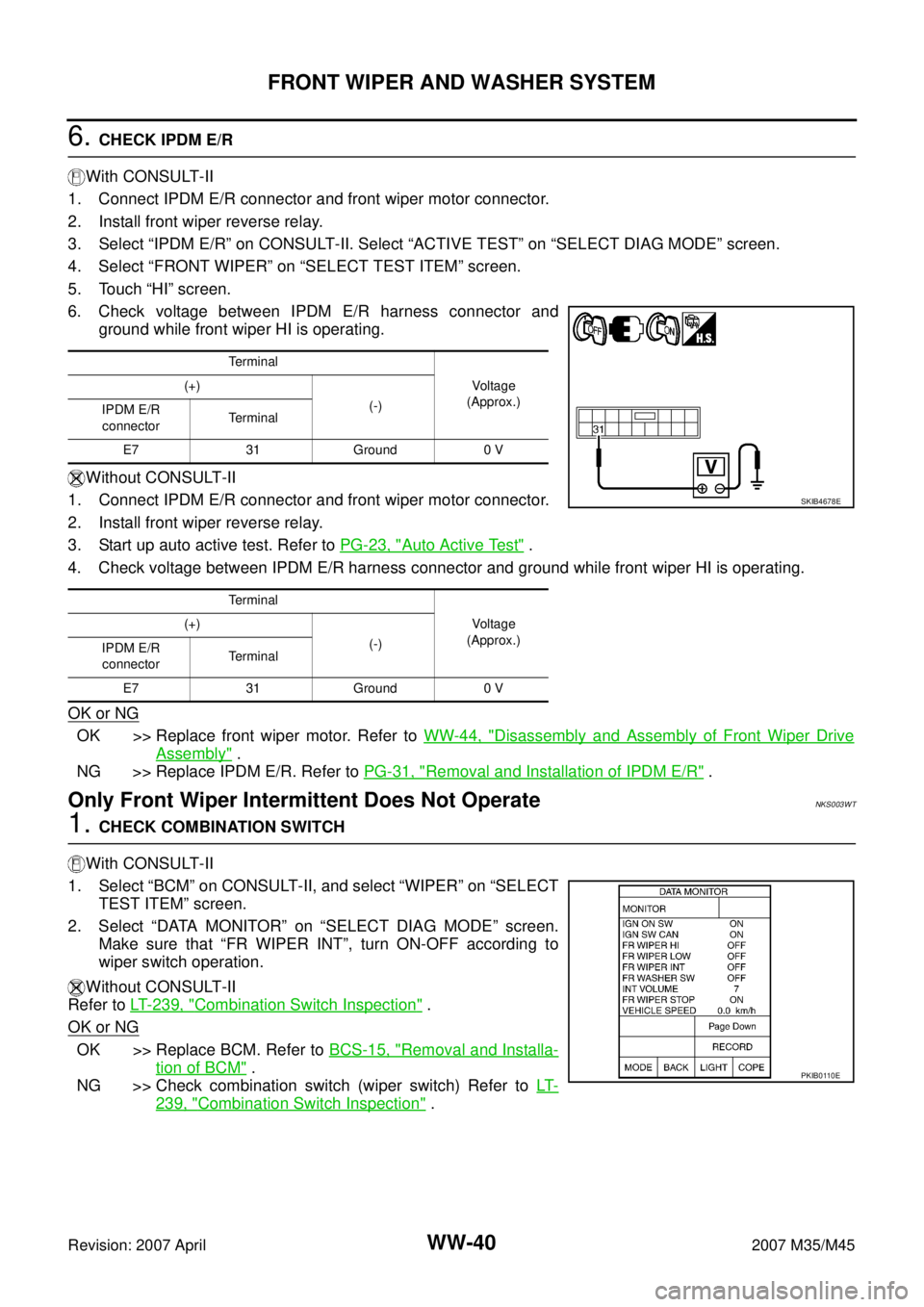
6. CHECK IPDM E/R
With CONSULT-II
1. Connect IPDM E/R connector and front wiper motor connector.
2. Install front wiper reverse relay.
3. Select “IPDM E/R” on CONSULT-II. Select “ACTIVE TEST” on “SELECT DIAG MODE” screen.
4. Select “FRONT WIPER” on “SELECT TEST ITEM” screen.
5. Touch “HI” screen.
6. Check voltage between IPDM E/R harness connector and
ground while front wiper HI is operating.
Without CONSULT-II
1. Connect IPDM E/R connector and front wiper motor connector.
2. Install front wiper reverse relay.
3. Start up auto active test. Refer to PG-23, "
Auto Active Test" .
4. Check voltage between IPDM E/R harness connector and ground while front wiper HI is operating.
OK or NG
OK >> Replace front wiper motor. Refer to WW-44, "Disassembly and Assembly of Front Wiper Drive
Assembly" .
NG >> Replace IPDM E/R. Refer to PG-31, "
Removal and Installation of IPDM E/R" .
Only Front Wiper Intermittent Does Not OperateNKS003WT
1. CHECK COMBINATION SWITCH
With CONSULT-II
1. Select “BCM” on CONSULT-II, and select “WIPER” on “SELECT
TEST ITEM” screen.
2. Select “DATA MONITOR” on “SELECT DIAG MODE” screen.
Make sure that “FR WIPER INT”, turn ON-OFF according to
wiper switch operation.
Without CONSULT-II
Refer to LT- 2 3 9 , "
Combination Switch Inspection" .
OK or NG
OK >> Replace BCM. Refer to BCS-15, "Removal and Installa-
tion of BCM" .
NG >> Check combination switch (wiper switch) Refer to LT-
239, "Combination Switch Inspection" .
Te r m i n a l
Voltage
(Approx.) (+)
(-)
IPDM E/R
connectorTe r m i n a l
E7 31 Ground 0 V
Te r m i n a l
Voltage
(Approx.) (+)
(-)
IPDM E/R
connectorTe r m i n a l
E7 31 Ground 0 V
SKIB4678E
PKIB0110E
Page 4634 of 4647
FRONT WIPER AND WASHER SYSTEM
WW-43
C
D
E
F
G
H
I
J
L
MA
B
WW
Revision: 2007 April2007 M35/M45
Removal and Installation of Front Wiper Arms, Adjustment of Wiper Arms Stop
Location
NKS003WY
REMOVAL
1. Turn wiper switch ON to operate wiper motor, and then turn wiper switch OFF (auto stop).
2. Open hood, remove arm caps, and remove wiper arm nuts.
3. Raise wiper arms, and remove wiper arms from the vehicle.
INSTALLATION
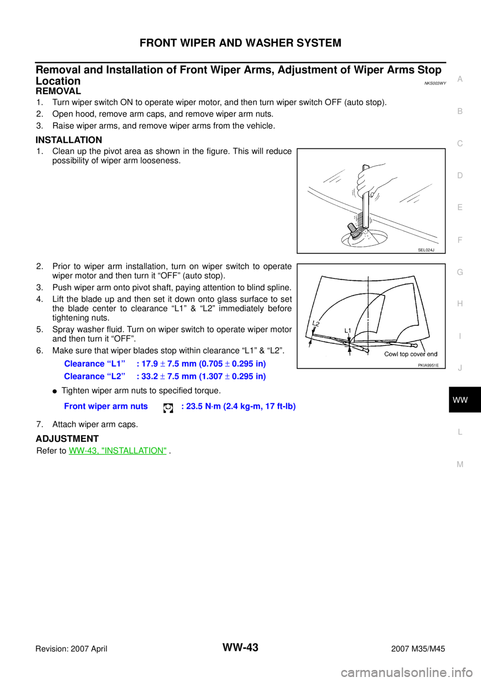
1. Clean up the pivot area as shown in the figure. This will reduce
possibility of wiper arm looseness.
2. Prior to wiper arm installation, turn on wiper switch to operate
wiper motor and then turn it “OFF” (auto stop).
3. Push wiper arm onto pivot shaft, paying attention to blind spline.
4. Lift the blade up and then set it down onto glass surface to set
the blade center to clearance “L1” & “L2” immediately before
tightening nuts.
5. Spray washer fluid. Turn on wiper switch to operate wiper motor
and then turn it “OFF”.
6. Make sure that wiper blades stop within clearance “L1” & “L2”.
�Tighten wiper arm nuts to specified torque.
7. Attach wiper arm caps.
ADJUSTMENT
Refer to WW-43, "INSTALLATION" .
SEL024J
Clearance “L1” : 17.9 ± 7.5 mm (0.705 ± 0.295 in)
Clearance “L2” : 33.2 ± 7.5 mm (1.307 ± 0.295 in)
Front wiper arm nuts : 23.5 N·m (2.4 kg-m, 17 ft-lb)PKIA9951E
Page 4635 of 4647
WW-44
FRONT WIPER AND WASHER SYSTEM
Revision: 2007 April2007 M35/M45
Removal and Installation of Front Wiper Drive AssemblyNKS003WZ
REMOVAL
1. Operate front wiper motor, and stop at the auto stop position.
2. Remove wiper arms. Refer to WW-43, "
REMOVAL" .
3. Remove cowl top cover. Refer to EI-18, "
COWL TOP" .
4. Disconnect wiper motor connector and remove connector clips.
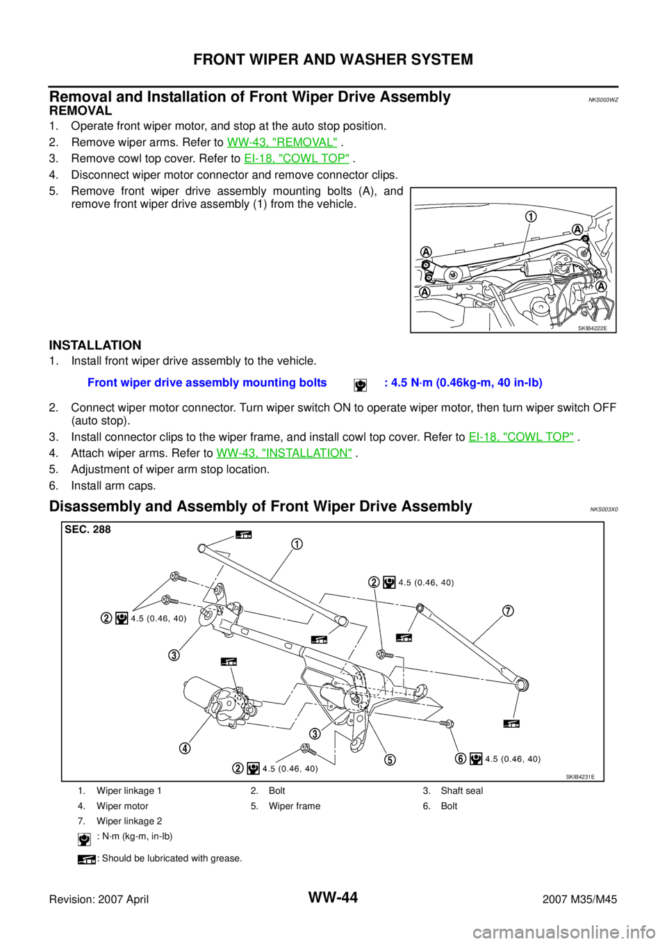
5. Remove front wiper drive assembly mounting bolts (A), and
remove front wiper drive assembly (1) from the vehicle.
INSTALLATION
1. Install front wiper drive assembly to the vehicle.
2. Connect wiper motor connector. Turn wiper switch ON to operate wiper motor, then turn wiper switch OFF
(auto stop).
3. Install connector clips to the wiper frame, and install cowl top cover. Refer to EI-18, "
COWL TOP" .
4. Attach wiper arms. Refer to WW-43, "
INSTALLATION" .
5. Adjustment of wiper arm stop location.
6. Install arm caps.
Disassembly and Assembly of Front Wiper Drive AssemblyNKS003X0
SKIB4222E
Front wiper drive assembly mounting bolts : 4.5 N·m (0.46kg-m, 40 in-lb)
1. Wiper linkage 1 2. Bolt 3. Shaft seal
4. Wiper motor 5. Wiper frame 6. Bolt
7. Wiper linkage 2
: N·m (kg-m, in-lb)
: Should be lubricated with grease.
SKIB4231E
Page 4636 of 4647
FRONT WIPER AND WASHER SYSTEM
WW-45
C
D
E
F
G
H
I
J
L
MA
B
WW
Revision: 2007 April2007 M35/M45
DISASSEMBLY
1. Remove wiper linkage from wiper motor and motor frame.
2. Remove wiper motor mounting bolts, and remove wiper motor from wiper frame.
CAUTION:
Be careful not to bend linkage and not to damage the resin part of ball joint when removing wiper link-
age.
ASSEMBLY
1. Connect wiper motor connector. Turn wiper switch ON to operate wiper motor, and then turn wiper switch
OFF (auto stop).
2. Disconnect wiper motor connector.
3. Install wiper motor to wiper frame.
4. Install wiper linkage to wiper frame and wiper motor.
CAUTION:
�Never drop the wiper motor or cause it to contact other parts.
�Check grease conditions of the motor arm and wiper linkage joint (at retainer). Apply grease if
necessary.
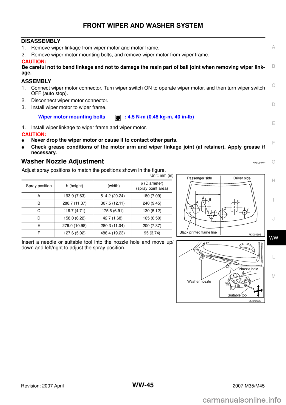
Washer Nozzle AdjustmentNKS004HP
Adjust spray positions to match the positions shown in the figure.
Unit: mm (in)
Insert a needle or suitable tool into the nozzle hole and move up/
down and left/right to adjust the spray position.Wiper motor mounting bolts : 4.5 N·m (0.46 kg-m, 40 in-lb)
Spray position h (height) l (width)φ (Diameter)
(spray point area)
A 193.9 (7.63) 514.2 (20.24) 180 (7.09)
B 288.7 (11.37) 307.5 (12.11) 240 (9.45)
C 119.7 (4.71) 175.6 (6.91) 130 (5.12)
D 158.0 (6.22) 42.7 (1.68) 165 (6.50)
E 279.0 (10.98) 280.3 (11.04) 200 (7.87)
F 127.6 (5.02) 488.4 (19.23) 95 (3.74)
PKID0429E
SKIB4250E