Page 4018 of 4647

POWER STEERING OIL PUMP
PS-37
C
D
E
F
H
I
J
K
L
MA
B
PS
Revision: 2007 April2007 M35/M45
ASSEMBLY
NOTE:
Secure oil pump in a vise if necessary.
CAUTION:
Use copper plates when securing in a vise.
1. Apply recommended grease to oil seal lips. Apply recommended
fluid to around oil seal, and then install oil seal to body assembly
using the drift [SST].
2. Install bracket to body assembly, and then tighten mounting
bolts to the specified torque.
3. If dowel pin has been removed, insert it into body assembly by
hand. If cannot be inserted by hand, lightly tap with a hammer.
4. Install flow control valve A, flow control valve spring and flow
control valve B assembly as shown in the figure.
5. Install front side plate (3) with dowel pin (2) on flow control valve
A (1) side as shown in the figure aligning with front side plate
cutout (A) to body assembly (4).
6. Install cam ring as shown in the figure.
7. Install pulley to body assembly.
CAUTION:
Do not damage oil seal when installing pulley.
SGIA0527E
SGIA0526E
SGIA1189E
SGIA0612E
Page 4019 of 4647

PS-38
POWER STEERING OIL PUMP
Revision: 2007 April2007 M35/M45
8. Install rotor so that mark faces body assembly, and then install it
to pulley shaft.
9. Install vane to rotor so that arc of vane faces cam ring side.
10. Install rotor snap ring to slit of pulley shaft using a hammer and a
10 mm (0.39 in) socket.
CAUTION:
�Do not damage rotor and pulley shaft.
�Power steering oil pump assembly must be replaced if
rotor is damaged.
11. Install rear side plate with dowel pin A on flow control valve A
side as shown in the figure aligning with rear side plate cutout B
to cartridge.
12. Apply recommended fluid to O-ring, and then install O-ring to
body assembly.
13. Apply recommended fluid to O-ring, and then install O-ring to
rear side plate.
14. Apply recommended fluid to Teflon ring, and then install Teflon
ring to rear side plate.
15. Install rear cover to body assembly, and then tighten mounting
bolts to the specified torque.
16. Apply recommended fluid to O-ring, and then install O-ring to body assembly.
17. Install suction pipe to body assembly.
SGIA0989E
SGIA0613E
SGIA0063E
SGIA0530E
Page 4020 of 4647
HYDRAULIC LINE
PS-39
C
D
E
F
H
I
J
K
L
MA
B
PS
Revision: 2007 April2007 M35/M45
HYDRAULIC LINEPFP:49721
Removal and InstallationNGS000DI
COMPONENTS (VQ35DE 2WD MODELS)
1. Reservoir tank 2. Reservoir tank bracket 3. Suction hose
4. High pressure hose 5. Oil pump assembly 6. Steering gear assembly
7. Low pressure piping 8. High pressure piping 9. O-ring
SGIA1390E
Page 4021 of 4647
PS-40
HYDRAULIC LINE
Revision: 2007 April2007 M35/M45
10. Eye-bolt 11. Copper washer 12. Eye-joint (assembled to high-pres-
sure side hose)
13. Pressure sensor 14. Oil pump bracket
Refer to GI-11, "
Components" , and the followings for the symbols in the figure.
: Apply power steering fluid.
Page 4022 of 4647
HYDRAULIC LINE
PS-41
C
D
E
F
H
I
J
K
L
MA
B
PS
Revision: 2007 April2007 M35/M45
COMPONENTS (VQ35DE AWD MODELS)
1. Reservoir tank 2. Reservoir tank bracket 3. Suction hose
4. High-pressure hose 5. Oil pump assembly 6. Steering gear assembly
7. Low pressure piping 8. High pressure piping 9. O-ring
10. Eye-bolt 11. Copper washer 12. Eye-joint (assembled to high-pres-
sure side hose)
13. Pressure sensor 14. Oil pump bracket
SGIA1191E
Page 4023 of 4647
PS-42
HYDRAULIC LINE
Revision: 2007 April2007 M35/M45
Refer to GI-11, "Components" , and the followings for the symbols in the figure.
: Apply power steering fluid.
Page 4024 of 4647
HYDRAULIC LINE
PS-43
C
D
E
F
H
I
J
K
L
MA
B
PS
Revision: 2007 April2007 M35/M45
COMPONENTS (VK45DE MODELS)
1. Reservoir tank 2. Reservoir tank bracket 3. Suction hose
4. High-pressure hose 5. Oil pump assembly 6. Steering gear assembly
7. Low pressure piping 8. High pressure piping 9. O-ring
10. Eye-bolt 11. Copper washer 12. Eye-joint (assembled to high-pres-
sure side hose)
13. Pressure sensor 14. Oil pump bracket
SGIA1391E
Page 4025 of 4647
PS-44
HYDRAULIC LINE
Revision: 2007 April2007 M35/M45
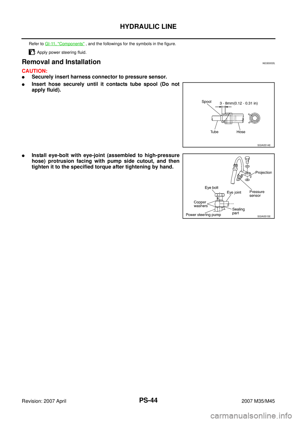
Removal and InstallationNGS000DL
CAUTION:
�Securely insert harness connector to pressure sensor.
�Insert hose securely until it contacts tube spool (Do not
apply fluid).
�Install eye-bolt with eye-joint (assembled to high-pressure
hose) protrusion facing with pump side cutout, and then
tighten it to the specified torque after tightening by hand.
Refer to GI-11, "Components" , and the followings for the symbols in the figure.
: Apply power steering fluid.
SGIA0514E
SGIA0515E

1. Reservoir tank 2. Reservoir t")

13. Pressure sensor 14. Oil pump bracket
Refer to GI-11, \"")

1. Reservoir tank 2. Reservoir tank bracket 3. Suction hose
4. High-pressure hose 5. Oil")


1. Reservoir tank 2. Reservoir tank bracket 3. Suction hose
4. High-pressure hose 5. Oil pump")