Page 1024 of 4647
INTELLIGENT KEY SYSTEM
BL-91
C
D
E
F
G
H
J
K
L
MA
B
BL
Revision: 2007 April2007 M35/M45
Check Power Supply and Ground CircuitNIS001XM
1. CHECK POWER SUPPLY CIRCUIT
1. Turn ignition switch OFF.
2. Disconnect Intelligent Key unit connector.
3. Check voltage between Intelligent Key unit harness connector and ground.
OK or NG
OK >> GO TO 2.
NG >> Repair or replace Intelligent Key power supply circuit.
2. CHECK GROUND CIRCUIT
Check continuity between Intelligent Key unit harness connector and ground.
OK or NG
OK >> Power supply and ground circuits are OK.
NG >> Repair or replace the Intelligent Key unit ground circuit.
Terminals
Voltage (V)
(Approx.) (+)
(–)
Intelligent Key unit
connectorTerminal
M32 1
Ground Battery voltage
M3341
57
PIIB6251E
Intelligent Key unit connector Terminal
GroundContinuity
M3220
Ye s 40
M3356
72
PIIB6318E
Page 1025 of 4647
BL-92
INTELLIGENT KEY SYSTEM
Revision: 2007 April2007 M35/M45
Check Key SlotNIS001XN
1. CHECK KEY SLOT INPUT SIGNAL
Check voltage between Intelligent Key unit harness connector and ground.
OK or NG
OK >> Key slot is OK.
NG >> GO TO 2.
2. CHECK KEY SLOT POWER SUPPLY CIRCUIT
1. Turn ignition switch OFF.
2. Disconnect key slot connector.
3. Check voltage between slot connector and ground.
OK or NG
OK >> GO TO 3.
NG >> Repair or replace key slot power supply circuit.
3. CHECK KEY SLOT
Check key slot.
OK or NG
OK >> GO TO 4.
NG >> Replace key slot.
Terminals
ConditionVoltage (V)
(Approx.) (+)
(–)
Intelligent Key
unit connectorTerminal
M32 19 GroundIntelligent Key inserted Battery voltage
Intelligent Key removed 0
PIIB6319E
Terminals
Voltage (V)
(Approx.) (+)
(–)
Key slot connector Terminal
M14 1 Ground Battery voltage
PIIB6320E
Terminal
Condition Continuity
Key slot
13Intelligent Key inserted Yes
Intelligent Key removed No
PIIB6321E
Page 1027 of 4647
BL-94
INTELLIGENT KEY SYSTEM
Revision: 2007 April2007 M35/M45
Check Door SwitchNIS001XO
1. CHECK DOOR SWITCH INPUT SIGNAL
With CONSULT-II
Check door switches (“DOOR SW-DR”, “DOOR SW-AS”, “DOOR SW-RL” and “DOOR SW-RR”) in “DATA
MONITOR” mode with CONSULT-II.
Without CONSULT-II
1. Turn ignition switch OFF.
2. Check voltage between BCM connector and ground.
OK or NG
OK >> Door switch circuit is OK.
NG >> GO TO 2.
Monitor item Condition
DOOR SW-DR
CLOSE → OPEN: OFF → ON DOOR SW-AS
DOOR SW-RL
DOOR SW-RR
PIIA6469E
Terminals
Door conditionVoltage (V)
(Approx.) (+)
(–)
BCM
connectorTerminal
M112
GroundFront
passenger
sideOPEN 0
CLOSE Battery voltage
13Rear RH
sideOPEN 0
CLOSE Battery voltage
M362 Driver sideOPEN 0
CLOSE Battery voltage
63Rear LH
sideOPEN 0
CLOSE Battery voltage
PIIB6324E
Page 1029 of 4647
BL-96
INTELLIGENT KEY SYSTEM
Revision: 2007 April2007 M35/M45
4. CHECK BCM OUTPUT SIGNAL
1. Connect BCM connector.
2. Check voltage between BCM connector and ground.
OK or NG
OK >> Check the condition of harness and connector.
NG >> Replace BCM.
Terminals
Voltage (V)
(Approx.) (+)
(–)
BCM connector Terminal
M112
Ground Battery voltage 13
M362
63
PIIB6324E
Page 1030 of 4647
INTELLIGENT KEY SYSTEM
BL-97
C
D
E
F
G
H
J
K
L
MA
B
BL
Revision: 2007 April2007 M35/M45
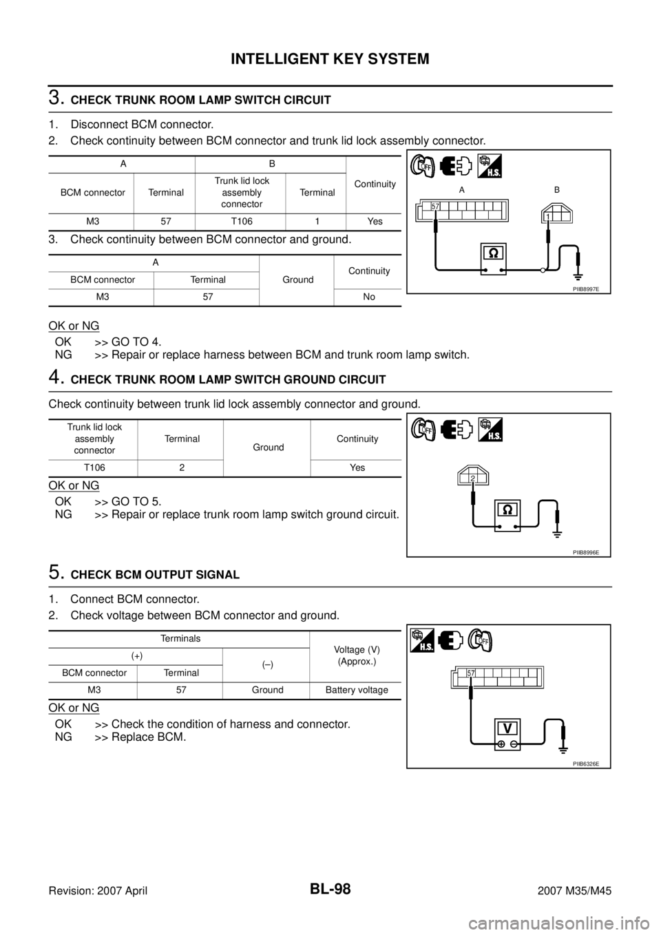
Check Trunk Room Lamp SwitchNIS001XP
1. CHECK TRUNK ROOM LAMP SWITCH INPUT SIGNAL
With CONSULT-II
Check (“TRUNK SW”) in “DATA MONITOR” mode with CONSULT-II.
Without CONSULT-II
1. Turn ignition switch OFF.
2. Check voltage between BCM connector and ground.
OK or NG
OK >> Trunk room lamp switch circuit is OK.
NG >> GO TO 2.
2. CHECK TRUNK ROOM LAMP SWITCH
1. Turn ignition switch OFF.
2. Disconnect trunk lid lock assembly connector.
3. Check trunk room lamp switch.
OK or NG
OK >> GO TO 3.
NG >> Replace trunk room lamp switch.
Monitor item Condition
TRUNK SWOPEN : ON
CLOSE : OFF
PIIB1362E
Terminals
Trunk
conditionVoltage (V)
(Approx.) (+)
(–)
BCM connector Terminal
M3 57 GroundOPEN 0
CLOSE Battery voltage
PIIB6326E
Terminal
Trunk condition Continuity
Trunk room lamp switch
12OPEN Yes
CLOSE No
PIIB8995E
Page 1031 of 4647

BL-98
INTELLIGENT KEY SYSTEM
Revision: 2007 April2007 M35/M45
3. CHECK TRUNK ROOM LAMP SWITCH CIRCUIT
1. Disconnect BCM connector.
2. Check continuity between BCM connector and trunk lid lock assembly connector.
3. Check continuity between BCM connector and ground.
OK or NG
OK >> GO TO 4.
NG >> Repair or replace harness between BCM and trunk room lamp switch.
4. CHECK TRUNK ROOM LAMP SWITCH GROUND CIRCUIT
Check continuity between trunk lid lock assembly connector and ground.
OK or NG
OK >> GO TO 5.
NG >> Repair or replace trunk room lamp switch ground circuit.
5. CHECK BCM OUTPUT SIGNAL
1. Connect BCM connector.
2. Check voltage between BCM connector and ground.
OK or NG
OK >> Check the condition of harness and connector.
NG >> Replace BCM.
AB
Continuity
BCM connector TerminalTrunk lid lock
assembly
connectorTerminal
M3 57 T106 1 Yes
A
GroundContinuity
BCM connector Terminal
M3 57 No
PIIB8997E
Trunk lid lock
assembly
connectorTerminal
GroundContinuity
T106 2 Yes
PIIB8996E
Terminals
Voltage (V)
(Approx.) (+)
(–)
BCM connector Terminal
M3 57 Ground Battery voltage
PIIB6326E
Page 1036 of 4647

INTELLIGENT KEY SYSTEM
BL-103
C
D
E
F
G
H
J
K
L
MA
B
BL
Revision: 2007 April2007 M35/M45
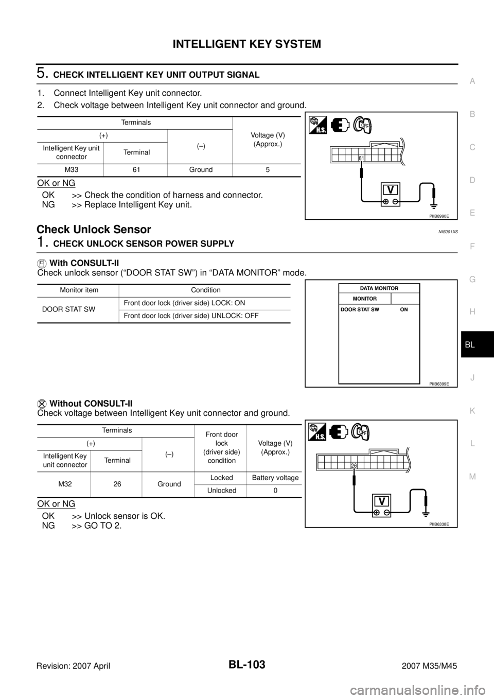
5. CHECK INTELLIGENT KEY UNIT OUTPUT SIGNAL
1. Connect Intelligent Key unit connector.
2. Check voltage between Intelligent Key unit connector and ground.
OK or NG
OK >> Check the condition of harness and connector.
NG >> Replace Intelligent Key unit.
Check Unlock SensorNIS001XS
1. CHECK UNLOCK SENSOR POWER SUPPLY
With CONSULT-II
Check unlock sensor (“DOOR STAT SW”) in “DATA MONITOR” mode.
Without CONSULT-II
Check voltage between Intelligent Key unit connector and ground.
OK or NG
OK >> Unlock sensor is OK.
NG >> GO TO 2.
Terminals
Voltage (V)
(Approx.) (+)
(–)
Intelligent Key unit
connectorTerminal
M33 61 Ground 5
PIIB8990E
Monitor item Condition
DOOR STAT SWFront door lock (driver side) LOCK: ON
Front door lock (driver side) UNLOCK: OFF
PIIB6399E
Terminals
Front door
lock
(driver side)
conditionVoltage (V)
(Approx.) (+)
(–)
Intelligent Key
unit connectorTerminal
M32 26 GroundLocked Battery voltage
Unlocked 0
PIIB6338E
Page 1037 of 4647

BL-104
INTELLIGENT KEY SYSTEM
Revision: 2007 April2007 M35/M45
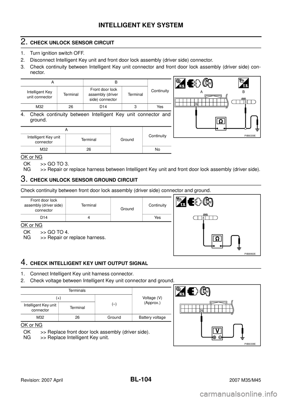
2. CHECK UNLOCK SENSOR CIRCUIT
1. Turn ignition switch OFF.
2. Disconnect Intelligent Key unit and front door lock assembly (driver side) connector.
3. Check continuity between Intelligent Key unit connector and front door lock assembly (driver side) con-
nector.
4. Check continuity between Intelligent Key unit connector and
ground.
OK or NG
OK >> GO TO 3.
NG >> Repair or replace harness between Intelligent Key unit and front door lock assembly (driver side).
3. CHECK UNLOCK SENSOR GROUND CIRCUIT
Check continuity between front door lock assembly (driver side) connector and ground.
OK or NG
OK >> GO TO 4.
NG >> Repair or replace harness.
4. CHECK INTELLIGENT KEY UNIT OUTPUT SIGNAL
1. Connect Intelligent Key unit harness connector.
2. Check voltage between Intelligent Key unit connector and ground.
OK or NG
OK >> Replace front door lock assembly (driver side).
NG >> Replace Intelligent Key unit.
AB
Continuity
Intelligent Key
unit connectorTe r m i n a l Front door lock
assembly (driver
side) connectorTerminal
M32 26 D14 3 Yes
A
GroundContinuity
Intelligent Key unit
connectorTerminal
M32 26 No
PIIB6339E
Front door lock
assembly (driver side)
connectorTerminal
GroundContinuity
D14 4 Yes
PIIB8992E
Terminals
Voltage (V)
(Approx.) (+)
(–)
Intelligent Key unit
connectorTerminal
M32 26 Ground Battery voltage
PIIB6338E