Page 4212 of 4647

AUTOMATIC DRIVE POSITIONER
SE-13
C
D
E
F
G
H
J
K
L
MA
B
SE
Revision: 2007 April2007 M35/M45
*: Door mirror operation starts with the start of seat sliding operation.
Storing Memory Procedure
1. Turn ignition switch to ON.
2. Shift A/T selector lever to P position.
3. Adjust position of driver seat, steering and mirror position.
4. Press set switch.
�Indicator LED for which driver seat positions are already retained in memory is illuminated for 5 sec-
onds.
�Indicator LED for which driver seat positions are not retained in memory is illuminated for 0.5 second.
5. Press memory switch for which driver seat positions are to be entered in memory for more than 0.5 sec-
ond within 5 seconds after pressing the set switch (during the indicator LED is illuminated).
�To enter driver seat positions in blank memory, indicator LED will be illuminated for 5 seconds.
�To modify driver seat positions, indicator LED will be turned OFF for 0.5 second then illuminated for 5
seconds.
6.
�If you need setting of INTELLIGENT KEY INTERLOCK OPERATION, continue this procedure.
�If you don't need setting of INTELLIGENT KEY INTERLOCK OPERATION, the procedure is finished.
Conform the operations of each part with the MEMORY OPERATION.
7. Press intelligent key unlock button within 5 seconds after pressing memory switch.
(While memory switch LED is illuminated.)
8. Conform the operations of each part with MEMORY OPERATION and INTELLIGENT KEY INTERLOCK
OPERATION.
NOTE:
�Driving position is erased from the memory when battery cable is disconnected.
Order of priority Operated portion
1* Seat sliding
2 Steering telescopic
3 Steering wheel tilt
4 Seat reclining
5 Seat lifter (front)
6 Seat lifter (rear)
Page 4230 of 4647

AUTOMATIC DRIVE POSITIONER
SE-31
C
D
E
F
G
H
J
K
L
MA
B
SE
Revision: 2007 April2007 M35/M45
Terminals and Reference Values for BCMNIS0025W
Terminals and Reference Value for Intelligent Key UnitNIS0025X
Te r m i -
nal Wire
colorItemSignal
Input/OutputConditionVoltage (V)
(Approx)
11 V Power source (ACC) InputIgnition switch
(ACC or ON position)Battery voltage
37 LG Key switch signal InputKey switch ON
(Key is inserted in key slot)Battery voltage
Key switch OFF
(Key is remove from key slot)0
38 W Power source (IGN) InputIgnition switch
(ON or START position)Battery voltage
39 L CAN-H Input/Output — —
40 P CAN-L Input/Output — —
42 P Power source (Fuse) Input — Battery voltage
52 B Ground — — 0
55 W Power source (Fusible link) Input — Battery voltage
62 V Drive side door switch Input ON (Open) → OFF (Closed) 0 → Battery voltage
Termi-
nalWire
ColorItemSignal
Input/OutputCondition
Voltage (V)
Approx. Ignition
Switch
PositionOperation or Conditions
1 SB Power source (Fuse) Input — — Battery voltage
19 BR/Y Key switch signal Input LOCKInsert Intelligent Key into key slot. Battery voltage
Remove Intelligent Key from key slot. 0
20 B Ground — ON — 0
27 V P range switch Input —Selector lever is in “P” position. 0
Other than above Battery voltage
37 P CAN-L Input/Output — — —
38 L CAN-H Input/Output — — —
40 B Ground — ON — 0
41 Y Power source (Fuse) Input — — Battery voltage
56 B Ground — — — 0
57 L Power source (Fuse) Input — — Battery voltage
58 OA/T device power
supply Output —Wake up state Battery voltage
Sleep state 0
72 B Ground — ON 0
Page 4238 of 4647

AUTOMATIC DRIVE POSITIONER
SE-39
C
D
E
F
G
H
J
K
L
MA
B
SE
Revision: 2007 April2007 M35/M45ACTIVE TEST
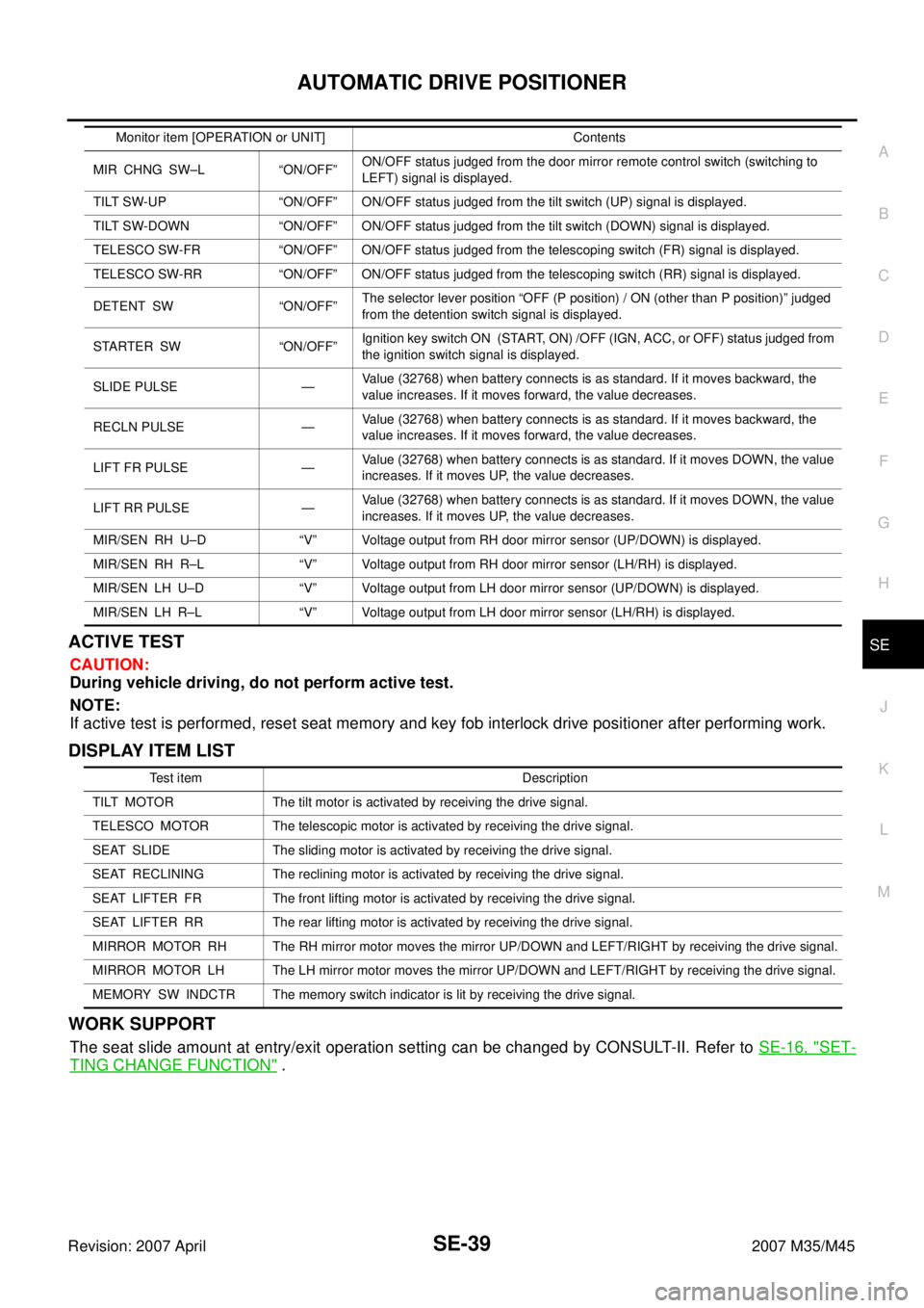
CAUTION:
During vehicle driving, do not perform active test.
NOTE:
If active test is performed, reset seat memory and key fob interlock drive positioner after performing work.
DISPLAY ITEM LIST
WORK SUPPORT
The seat slide amount at entry/exit operation setting can be changed by CONSULT-II. Refer to SE-16, "SET-
TING CHANGE FUNCTION" .
MIR CHNG SW–L “ON/OFF”ON/OFF status judged from the door mirror remote control switch (switching to
LEFT) signal is displayed.
TILT SW-UP “ON/OFF” ON/OFF status judged from the tilt switch (UP) signal is displayed.
TILT SW-DOWN “ON/OFF” ON/OFF status judged from the tilt switch (DOWN) signal is displayed.
TELESCO SW-FR “ON/OFF” ON/OFF status judged from the telescoping switch (FR) signal is displayed.
TELESCO SW-RR “ON/OFF” ON/OFF status judged from the telescoping switch (RR) signal is displayed.
DETENT SW “ON/OFF”The selector lever position “OFF (P position) / ON (other than P position)” judged
from the detention switch signal is displayed.
STARTER SW “ON/OFF”Ignition key switch ON (START, ON) /OFF (IGN, ACC, or OFF) status judged from
the ignition switch signal is displayed.
SLIDE PULSE —Value (32768) when battery connects is as standard. If it moves backward, the
value increases. If it moves forward, the value decreases.
RECLN PULSE —Value (32768) when battery connects is as standard. If it moves backward, the
value increases. If it moves forward, the value decreases.
LIFT FR PULSE —Value (32768) when battery connects is as standard. If it moves DOWN, the value
increases. If it moves UP, the value decreases.
LIFT RR PULSE —Value (32768) when battery connects is as standard. If it moves DOWN, the value
increases. If it moves UP, the value decreases.
MIR/SEN RH U–D “V” Voltage output from RH door mirror sensor (UP/DOWN) is displayed.
MIR/SEN RH R–L “V” Voltage output from RH door mirror sensor (LH/RH) is displayed.
MIR/SEN LH U–D “V” Voltage output from LH door mirror sensor (UP/DOWN) is displayed.
MIR/SEN LH R–L “V” Voltage output from LH door mirror sensor (LH/RH) is displayed.Monitor item [OPERATION or UNIT] Contents
Test item Description
TILT MOTOR The tilt motor is activated by receiving the drive signal.
TELESCO MOTOR The telescopic motor is activated by receiving the drive signal.
SEAT SLIDE The sliding motor is activated by receiving the drive signal.
SEAT RECLINING The reclining motor is activated by receiving the drive signal.
SEAT LIFTER FR The front lifting motor is activated by receiving the drive signal.
SEAT LIFTER RR The rear lifting motor is activated by receiving the drive signal.
MIRROR MOTOR RH The RH mirror motor moves the mirror UP/DOWN and LEFT/RIGHT by receiving the drive signal.
MIRROR MOTOR LH The LH mirror motor moves the mirror UP/DOWN and LEFT/RIGHT by receiving the drive signal.
MEMORY SW INDCTR The memory switch indicator is lit by receiving the drive signal.
Page 4411 of 4647

SRS-30
TROUBLE DIAGNOSIS
Revision: 2007 April2007 M35/M45
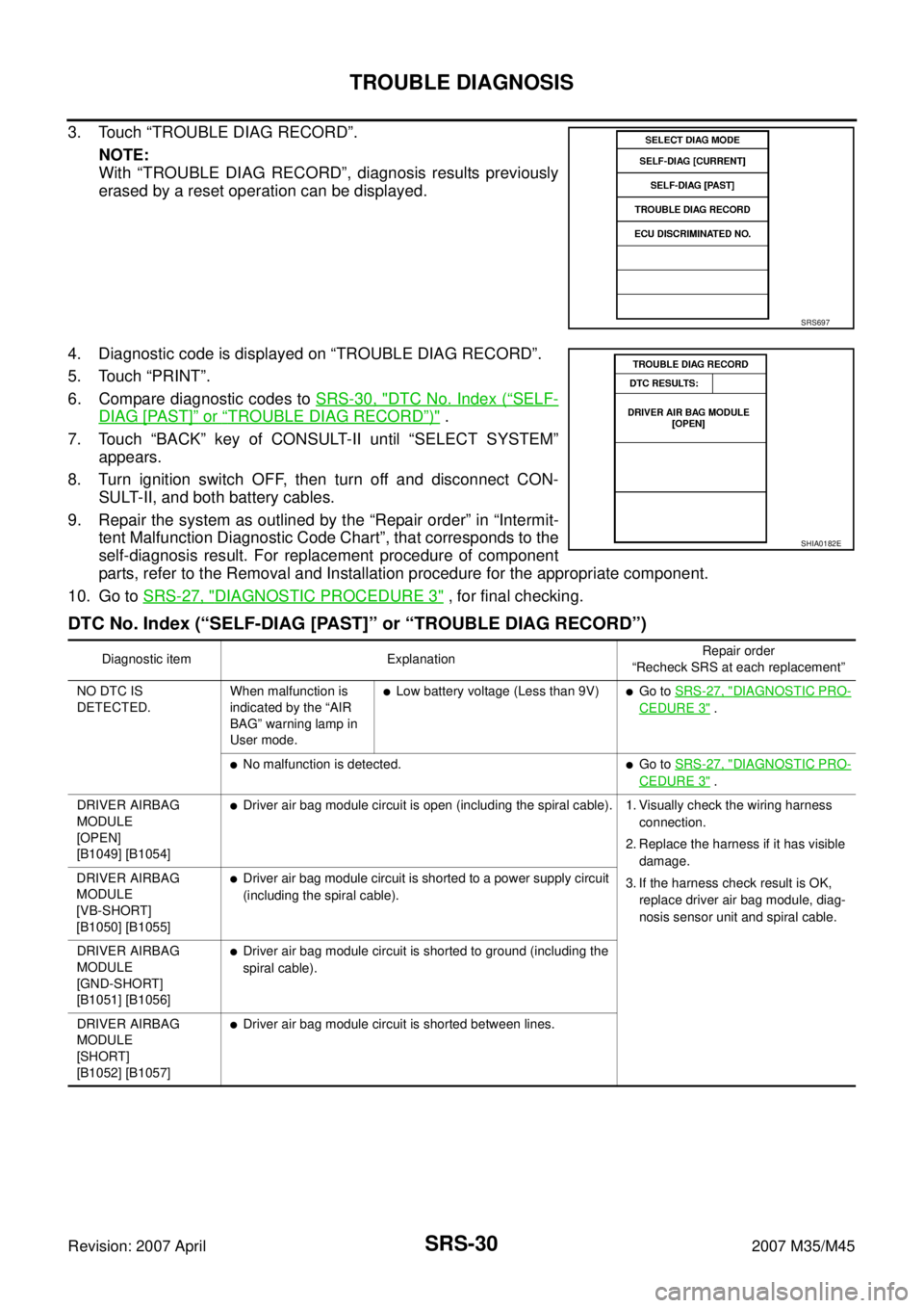
3. Touch “TROUBLE DIAG RECORD”.
NOTE:
With “TROUBLE DIAG RECORD”, diagnosis results previously
erased by a reset operation can be displayed.
4. Diagnostic code is displayed on “TROUBLE DIAG RECORD”.
5. Touch “PRINT”.
6. Compare diagnostic codes to SRS-30, "
DTC No. Index (“SELF-
DIAG [PAST]” or “TROUBLE DIAG RECORD”)" .
7. Touch “BACK” key of CONSULT-II until “SELECT SYSTEM”
appears.
8. Turn ignition switch OFF, then turn off and disconnect CON-
SULT-II, and both battery cables.
9. Repair the system as outlined by the “Repair order” in “Intermit-
tent Malfunction Diagnostic Code Chart”, that corresponds to the
self-diagnosis result. For replacement procedure of component
parts, refer to the Removal and Installation procedure for the appropriate component.
10. Go to SRS-27, "
DIAGNOSTIC PROCEDURE 3" , for final checking.
DTC No. Index (“SELF-DIAG [PAST]” or “TROUBLE DIAG RECORD”)
SRS697
SHIA0182E
Diagnostic item ExplanationRepair order
“Recheck SRS at each replacement”
NO DTC IS
DETECTED.When malfunction is
indicated by the “AIR
BAG” warning lamp in
User mode.
�Low battery voltage (Less than 9V)�Go to SRS-27, "DIAGNOSTIC PRO-
CEDURE 3" .
�No malfunction is detected.�Go to SRS-27, "DIAGNOSTIC PRO-
CEDURE 3" .
DRIVER AIRBAG
MODULE
[OPEN]
[B1049] [B1054]
�Driver air bag module circuit is open (including the spiral cable). 1. Visually check the wiring harness
connection.
2. Replace the harness if it has visible
damage.
3. If the harness check result is OK,
replace driver air bag module, diag-
nosis sensor unit and spiral cable. DRIVER AIRBAG
MODULE
[VB-SHORT]
[B1050] [B1055]
�Driver air bag module circuit is shorted to a power supply circuit
(including the spiral cable).
DRIVER AIRBAG
MODULE
[GND-SHORT]
[B1051] [B1056]
�Driver air bag module circuit is shorted to ground (including the
spiral cable).
DRIVER AIRBAG
MODULE
[SHORT]
[B1052] [B1057]
�Driver air bag module circuit is shorted between lines.