Page 4004 of 4647
POWER STEERING GEAR AND LINKAGE
PS-23
C
D
E
F
H
I
J
K
L
MA
B
PS
Revision: 2007 April2007 M35/M45
14. Push rack oil seal inside with a 29 mm (1.14 in) socket and an
extension bar to push out rack oil seal (inner side) from gear
housing assembly.
CAUTION:
Do not damage gear housing assembly and cylinder inner
wall. Gear housing assembly must be replaced if damaged
because it may cause fluid leakage.
INSPECTION AFTER DISASSEMBLY
Boot
Check boot for cracks, and replace it if a malfunction is detected.
Rack Assembly
Check rack for damage or wear, and replace it if a malfunction is detected.
Gear-Sub Assembly
�Check gear-sub assembly for damage or wear, and replace it if a malfunction is detected.
�Rotate gear-sub assembly and check for torque variation or rattle, and replace it if a malfunction is
detected.
Gear Housing Assembly
Check gear housing assembly for damage and scratches (inner wall). Replace if there are.
SGIA0179E
Page 4005 of 4647

PS-24
POWER STEERING GEAR AND LINKAGE
Revision: 2007 April2007 M35/M45
Outer Socket and Inner Socket
1. Ball joint swinging torque
�Hook a spring balance at the point shown in the figure and
pull the spring balance. Make sure that the spring balance
reads the specified value when ball stud and inner socket
start to move. Replace outer socket and steering gear assem-
bly if they are outside the standard.
2. Ball joint rotating torque
�Make sure that the reading is within the following specified
range using the preload gauge [SST]. Replace outer socket if
the reading is outside the specified value.
3. Ball joint axial end play
�Apply an axial load of 490 N (50 kg, 111 lb) to ball stud using a
dial gauge. Measure amount of stud movement, and then
make sure that the value is within the following specified
range. Replace outer socket and inner socket if the measured
value is outside the standard.
SGIA0896E
Items Outer socket Inner socket
Measuring point of spring balance Stud cotter pin mounting hole Measuring point at *mark shown in the figure
Swinging torque0.3 – 2.9 N·m
(0.03 – 0.29 kg-m, 3 – 25 in-lb)1.0–7.8 N·m
(0.11 – 0.79 kg-m, 9.0 – 69 in-lb)
Spring balance measurement4.81 – 45.7 N
(0.5 – 4.7 kg, 1.1 – 10.4 lb)8.9 – 64 N
(0.9 – 6.5 kg, 2.0 – 14.3 lb)
Outer socket rotating torque 0.3 – 2.9 N·m (0.03 – 0.29 kg-m, 3 – 25 in-lb)
SGIA0941E
Outer socket 0.5 mm (0.020 in) or less
Inner socket 0.2 mm (0.008 in) or less
SGIA0057E
Page 4008 of 4647
, and then screw in the adju")
POWER STEERING GEAR AND LINKAGE
PS-27
C
D
E
F
H
I
J
K
L
MA
B
PS
Revision: 2007 April2007 M35/M45
12. Apply recommended thread locking sealant to the thread (2
turns thread), and then screw in the adjusting screw until it
reaches height “H” from gear housing assembly measured
before disassembling.
13. Move rack assembly 10 strokes throughout the full stroke so that
the parts can fit with each other.
14. Measure pinion rotating torque within ±180° of neutral position
of the rack assembly using the preload gauge [SST] and preload
adapter [SST]. Stop the gear at the point where highest torque is
read.
15. Loosen adjusting screw and retighten to 5.4 N·m (0.55 kg-m, 48
in-lb), and then loosen by 20 to 40°.
16. Measure pinion rotating torque using the preload adapter [SST]
and preload gauge [SST] to make sure that the measured value
is within the standard. Readjust if the value is outside the stan-
dard. Replace steering gear assembly if the value is outside the
standard after readjusting or adjusting screw rotating torque is 5
N·m (0.51 kg-m, 44 in-lb) or less.
17. Apply recommended liquid gasket to inner socket and turn pinion fully to left with inner socket installed to
gear housing assembly.
18. Set dial gauge as shown in the figure. Measure vertical move-
ment of rack assembly when pinion is turned clockwise with
torque of 19.6 N·m (2.0 kg-m, 14 ft-lb). Readjust adjusting screw
angle if the measured value is outside the standard. Replace
steering gear assembly if the measured value is still outside the
standard or adjusting screw rotating torque is 5 N·m (0.51 kg-m,
44 in-lb) or less.
SGIA0624E
SGIA0942E
SGIA0936E
Pinion rotating torque standard 2WD AWD
Around neutral position (within±100°)
Average A1.95 - 2.58 N·m
(0.20 - 0.26 kg-m, 18 - 22 in-lb)2.27 - 3.05 N·m
(0.24 - 0.31 kg-m, 20 - 26 in-lb)
Maximum variation B 0.98 N·m (0.10 kg-m, 9.0 in-lb)
SGIA1185E
Page 4009 of 4647

PS-28
POWER STEERING GEAR AND LINKAGE
Revision: 2007 April2007 M35/M45
19. Install large end of boot to gear housing assembly.
20. Install small end of boot to inner socket boot mounting groove.
21. Install boot clamp to boot small end.
22. Install large side of boot clamp.
�Tighten large side of boot with boot clamp (stainless wire).
�Wrap clamp around boot groove for two turns. Insert a flat-
bladed screwdriver in loops on both ends of wire. Twist 4 to
4.5 turns while pulling them with force of approximately 98 N
(10 kg, 22 lb).
�Twist boot clamp as shown. Pay attention to relationship
between winding and twisting directions.
�Twisted point of clamp is in the opposite side of adjusting
screw (1) as shown in the figure (to prevent contact with other
parts).
Measuring pointRack axial direction 5 mm (0.20 in) from housing end surface
Rack radial direction Axial direction of the adjusting screw
Vertical movement of rack 0.265 mm (0.0104 in)
SGIA1325E
Wire length L : 370 mm (14.57 in)
SGIA0163E
SGIA0164E
SGIA1186E
Page 4010 of 4647
POWER STEERING GEAR AND LINKAGE
PS-29
C
D
E
F
H
I
J
K
L
MA
B
PS
Revision: 2007 April2007 M35/M45
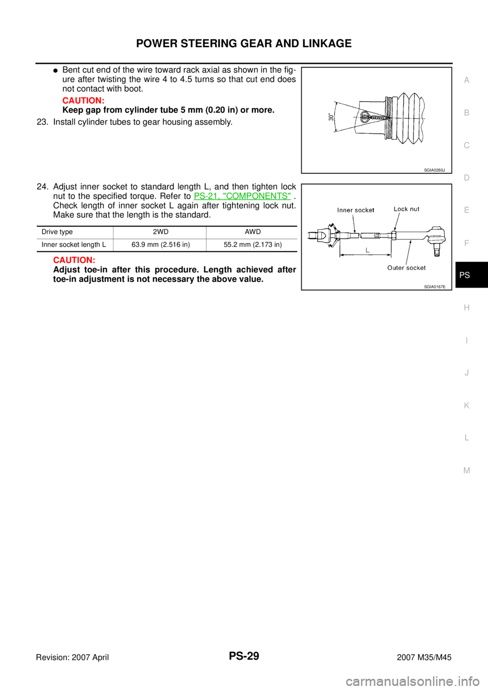
�Bent cut end of the wire toward rack axial as shown in the fig-
ure after twisting the wire 4 to 4.5 turns so that cut end does
not contact with boot.
CAUTION:
Keep gap from cylinder tube 5 mm (0.20 in) or more.
23. Install cylinder tubes to gear housing assembly.
24. Adjust inner socket to standard length L, and then tighten lock
nut to the specified torque. Refer to PS-21, "
COMPONENTS" .
Check length of inner socket L again after tightening lock nut.
Make sure that the length is the standard.
CAUTION:
Adjust toe-in after this procedure. Length achieved after
toe-in adjustment is not necessary the above value.
SGIA0260J
Drive type 2WD AWD
Inner socket length L 63.9 mm (2.516 in) 55.2 mm (2.173 in)
SGIA0167E
Page 4019 of 4647

PS-38
POWER STEERING OIL PUMP
Revision: 2007 April2007 M35/M45
8. Install rotor so that mark faces body assembly, and then install it
to pulley shaft.
9. Install vane to rotor so that arc of vane faces cam ring side.
10. Install rotor snap ring to slit of pulley shaft using a hammer and a
10 mm (0.39 in) socket.
CAUTION:
�Do not damage rotor and pulley shaft.
�Power steering oil pump assembly must be replaced if
rotor is damaged.
11. Install rear side plate with dowel pin A on flow control valve A
side as shown in the figure aligning with rear side plate cutout B
to cartridge.
12. Apply recommended fluid to O-ring, and then install O-ring to
body assembly.
13. Apply recommended fluid to O-ring, and then install O-ring to
rear side plate.
14. Apply recommended fluid to Teflon ring, and then install Teflon
ring to rear side plate.
15. Install rear cover to body assembly, and then tighten mounting
bolts to the specified torque.
16. Apply recommended fluid to O-ring, and then install O-ring to body assembly.
17. Install suction pipe to body assembly.
SGIA0989E
SGIA0613E
SGIA0063E
SGIA0530E
Page 4110 of 4647
PREPARATION
RSU-3
C
D
F
G
H
I
J
K
L
MA
B
RSU
Revision: 2007 April2007 M35/M45
PREPARATIONPFP:00002
Special Service Tools [SST]NES000J3
The actual shapes of Kent-Moore tools may differ from those of special service tools illustrated here.
Commercial Service ToolsNES000J4
Tool number
(Kent-Moore No.)
Tool nameDescription
ST3127S000
(See J25742-1)
Preload Gauge
1. GG91030000
(J25765)
Torque wrench
2. HT62940000
(—)
Socket adapter
3. HT62900000
(—)
Socket adapterMeasuring rotating torque of ball joint
NT124
Tool nameDescription
Power tool
�Removing wheel nuts
�Removing brake caliper assembly
�Removing rear suspension component
parts
PBIC0190E
Page 4593 of 4647

WW-2Revision: 2007 April2007 M35/M45 CHECK VALVE INSPECTION ............................. 47
Inspection of Front Wiper and Washer Switch Circuit ... 47
Removal and Installation of Front Wiper and Washer
Switch ..................................................................... 47
REMOVAL ........................................................... 47
INSTALLATION .................................................... 47
Removal and Installation of Washer Tank .............. 48
REMOVAL ........................................................... 48
INSTALLATION .................................................... 48
Removal and Installation of Washer Pump ............. 49
REMOVAL ........................................................... 49
INSTALLATION .................................................... 49
CIGARETTE LIGHTER ............................................. 50
Wiring Diagram — CIGAR — ................................. 50
Removal and Installation ........................................ 51
REMOVAL ........................................................... 51
INSTALLATION .................................................... 51POWER SOCKET ..................................................... 52
Wiring Diagram — P/SCKT — ................................ 52
Removal and Installation of Center Console Box
Power Socket .......................................................... 53
REMOVAL ............................................................ 53
INSTALLATION .................................................... 53
Removal and Installation of Center Console Box
Rear Side Power Socket ......................................... 53
REMOVAL ............................................................ 53
INSTALLATION .................................................... 53
HORN ........................................................................ 54
Wiring Diagram — HORN — .................................. 54
Removal and Installation ......................................... 55
REMOVAL ............................................................ 55
INSTALLATION .................................................... 55
 socket and an
extension bar to push out rack oil s")
![INFINITI M35 2007 Factory Service Manual PREPARATION
RSU-3
C
D
F
G
H
I
J
K
L
MA
B
RSU
Revision: 2007 April2007 M35/M45
PREPARATIONPFP:00002
Special Service Tools [SST]NES000J3
The actual shapes of Kent-Moore tools may differ from those of sp](/manual-img/42/57024/w960_57024-4109.png "INFINITI M35 2007 Factory Service Manual PREPARATION
RSU-3
C
D
F
G
H
I
J
K
L
MA
B
RSU
Revision: 2007 April2007 M35/M45
PREPARATIONPFP:00002
Special Service Tools [SST]NES000J3
The actual shapes of Kent-Moore tools may differ from those of sp")