Page 1205 of 4647

BL-272
IVIS (INFINITI VEHICLE IMMOBILIZER SYSTEM-NATS)
Revision: 2007 April2007 M35/M45
Trouble Diagnoses Flow Chart for IVIS (NATS)NIS0020P
NOTE:
This procedure is used to resolve the engine start malfunction when the Intelligent Key inserted into the key
slot is used.
1. CHECK ENGINE FOR START
Check that the engine can be started when Push-button ignition switch is operated with Intelligent Key
inserted into the key slot.
NG >> GO TO 2.
OK >> System is normal.
2. CONFIRM SELF DIAGNOSIS
Confirm SELF DIAGNOSIS “NATS V5.0” using CONSULT-II.
NOTE:
NATS program card is necessary to display the “SELF DIAGNOSIS”.
No malfunction>>Re-check the engine for start according to “Work Flow”. Refer to BL-269, "
Work Flow" .
Malfunction related to IVIS (NATS) is displayed.>>GO TO 3.
Malfunctions related to “DON'T ERASE BEFORE CHECKING ENG DIAG” and IVIS (NATS) are displayed>>
GO TO 6.
3. TROUBLE DIAGNOSIS
Repair IVIS (NATS) according to “SELF DIAGNOSIS”.
>> GO TO 4.
4. ERASE SELF DIAGNOSIS
Erase the record of “SELF DIAGNOSIS” using CONSULT-II.
>> GO TO 5.
5. CHECK ENGINE FOR START
Check that the engine can be started when Push-button ignition switch is operated with Intelligent Key
inserted into the key slot.
NG >> GO TO 2.
OK >> Inspection END.
6. CONFIRM SELF DIAGNOSIS DISPLAY
IVIS (NATS) malfunction information and “DON'T ERASE BEFORE CHECKING ENG DIAG” are displayed on
the CONSULT-II screen.
NOTE:
This indication means that malfunctions have been detected in IVIS (NATS) and engine control system.
>> GO TO 7.
Page 1206 of 4647
IVIS (INFINITI VEHICLE IMMOBILIZER SYSTEM-NATS)
BL-273
C
D
E
F
G
H
J
K
L
MA
B
BL
Revision: 2007 April2007 M35/M45
7. TROUBLE DIAGNOSIS
Repair IVIS (NATS) according to “SELF DIAGNOSIS”.
NOTE:
Do not erase “SELF DIAGNOSIS” using CONSULT-II.
>> GO TO 8.
8. CONFIRM SELF DIAGNOSIS
Confirm SELF DIAGNOSIS “ECM” using CONSULT-II.
>> GO TO 9.
9. CONFIRM SELF DIAGNOSIS DISPLAY
In case that malfunction of engine control system is displayed other than “NATS MALFUNCTION” in “SELF
DIAGNOSIS”, repair engine control system.
NOTE:
In case that only “NATS MALFUNCTION” is displayed, erase record of “SELF DIAGNOSIS”.
>> GO TO 10.
10. CHECK ENGINE FOR START
Check that the engine can be started when Push-button ignition switch is operated with Intelligent Key
inserted into the key slot.
NG >> GO TO 2.
OK >> GO TO 11.
11 . CONFIRM SELF DIAGNOSIS
Confirm SELF DIAGNOSIS “ECM” using CONSULT-II.
“NO DTC” is displayed.>>Inspection END.
Malfunction information is displayed.>>GO TO 2.
Page 1207 of 4647
BL-274
IVIS (INFINITI VEHICLE IMMOBILIZER SYSTEM-NATS)
Revision: 2007 April2007 M35/M45
Symptom Chart for Security IndicatorNIS0020Q
Security indicator does not turn ON or flash.
CAUTION:
�Follow Trouble Diagnosis Flowchart referring to “Diagnosis Procedure”. Determine malfunction-
ing condition before performing this diagnosis.
�Make sure that vehicle is under the condition shown in “Conditions of vehicle” before starting
diagnosis.
�Check systems shown in the “Action” column in this order.
CONDITIONS OF VEHICLE (OPERATING CONDITIONS)
�Intelligent Key is not inserted into key slot.
�Engine switch is not depressed.
Check Security Indicator HarnessNIS0020R
1. SECURITY INDICATOR LAMP ACTIVE TEST
With CONSULT-II
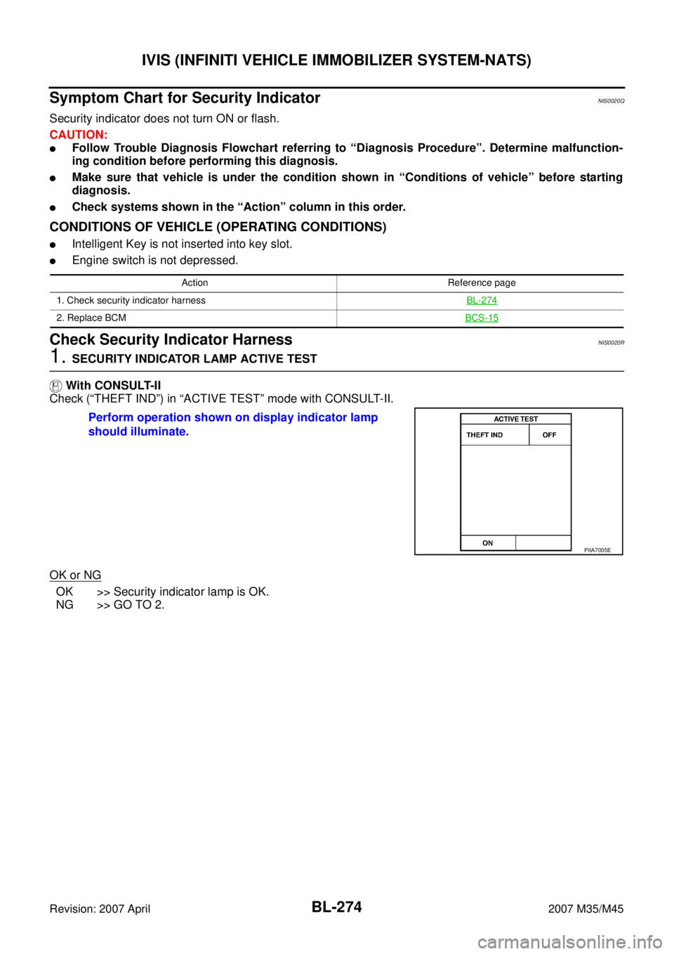
Check (“THEFT IND”) in “ACTIVE TEST” mode with CONSULT-II.
OK or NG
OK >> Security indicator lamp is OK.
NG >> GO TO 2.
Action Reference page
1. Check security indicator harnessBL-274
2. Replace BCMBCS-15
Perform operation shown on display indicator lamp
should illuminate.
PIIA7005E
Page 1209 of 4647
BL-276
IVIS (INFINITI VEHICLE IMMOBILIZER SYSTEM-NATS)
Revision: 2007 April2007 M35/M45
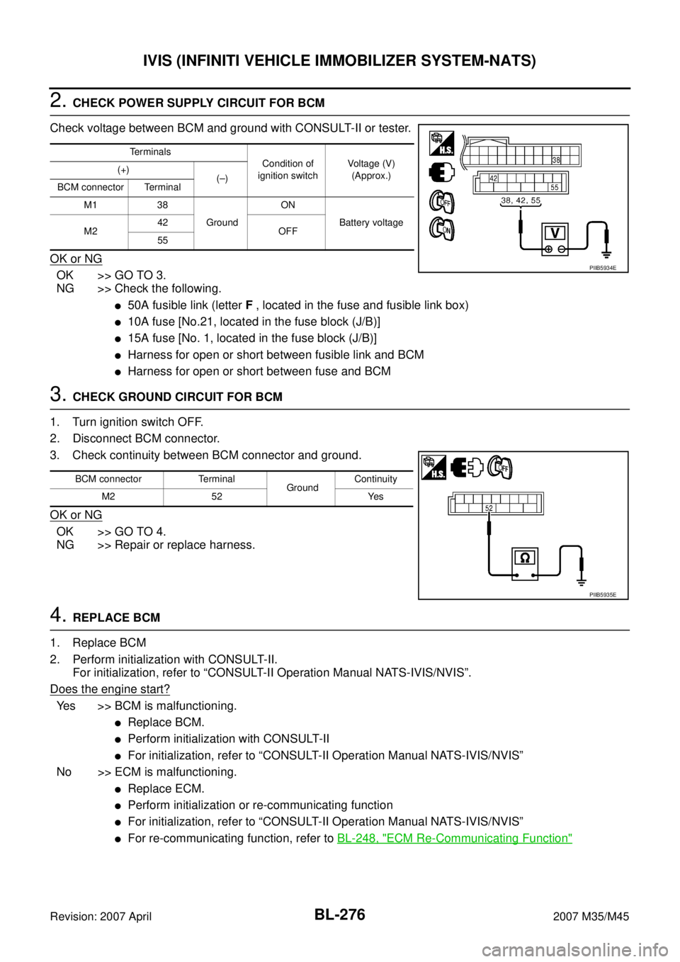
2. CHECK POWER SUPPLY CIRCUIT FOR BCM
Check voltage between BCM and ground with CONSULT-II or tester.
OK or NG
OK >> GO TO 3.
NG >> Check the following.
�50A fusible link (letter F , located in the fuse and fusible link box)
�10A fuse [No.21, located in the fuse block (J/B)]
�15A fuse [No. 1, located in the fuse block (J/B)]
�Harness for open or short between fusible link and BCM
�Harness for open or short between fuse and BCM
3. CHECK GROUND CIRCUIT FOR BCM
1. Turn ignition switch OFF.
2. Disconnect BCM connector.
3. Check continuity between BCM connector and ground.
OK or NG
OK >> GO TO 4.
NG >> Repair or replace harness.
4. REPLACE BCM
1. Replace BCM
2. Perform initialization with CONSULT-II.
For initialization, refer to “CONSULT-II Operation Manual NATS-IVIS/NVIS”.
Does the engine start?
Yes >> BCM is malfunctioning.
�Replace BCM.
�Perform initialization with CONSULT-II
�For initialization, refer to “CONSULT-II Operation Manual NATS-IVIS/NVIS”
No >> ECM is malfunctioning.
�Replace ECM.
�Perform initialization or re-communicating function
�For initialization, refer to “CONSULT-II Operation Manual NATS-IVIS/NVIS”
�For re-communicating function, refer to BL-248, "ECM Re-Communicating Function"
Te r m i n a l s
Condition of
ignition switchVoltage (V)
(Approx.) (+)
(–)
BCM connector Terminal
M1 38
GroundON
Battery voltage
M242
OFF
55
PIIB5934E
BCM connector Terminal
GroundContinuity
M2 52 Yes
PIIB5935E
Page 1210 of 4647
IVIS (INFINITI VEHICLE IMMOBILIZER SYSTEM-NATS)
BL-277
C
D
E
F
G
H
J
K
L
MA
B
BL
Revision: 2007 April2007 M35/M45
DTC P1611 ID DISCORD, IMM-ECMNIS0020T
Self-diagnostic results:
“ID DISCORD, IMM-ECM” displayed on CONSULT-II screen
1. CONFIRM SELF-DIAGNOSTIC RESULTS
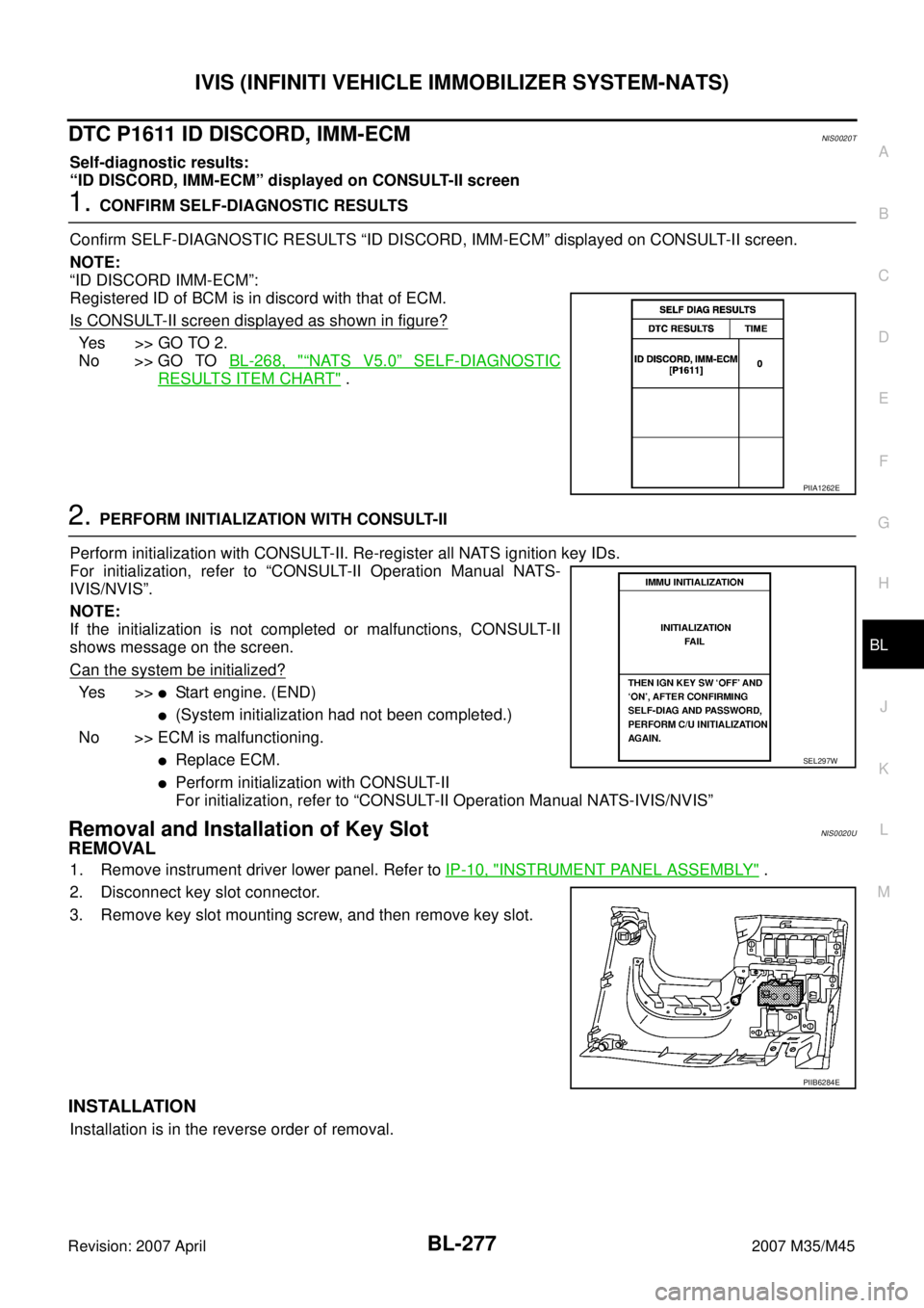
Confirm SELF-DIAGNOSTIC RESULTS “ID DISCORD, IMM-ECM” displayed on CONSULT-II screen.
NOTE:
“ID DISCORD IMM-ECM”:
Registered ID of BCM is in discord with that of ECM.
Is CONSULT-II screen displayed as shown in figure?
Ye s > > G O T O 2 .
No >> GO TO BL-268, "
“NATS V5.0” SELF-DIAGNOSTIC
RESULTS ITEM CHART" .
2. PERFORM INITIALIZATION WITH CONSULT-II
Perform initialization with CONSULT-II. Re-register all NATS ignition key IDs.
For initialization, refer to “CONSULT-II Operation Manual NATS-
IVIS/NVIS”.
NOTE:
If the initialization is not completed or malfunctions, CONSULT-II
shows message on the screen.
Can the system be initialized?
Ye s > >�Start engine. (END)
�(System initialization had not been completed.)
No >> ECM is malfunctioning.
�Replace ECM.
�Perform initialization with CONSULT-II
For initialization, refer to “CONSULT-II Operation Manual NATS-IVIS/NVIS”
Removal and Installation of Key SlotNIS0020U
REMOVAL
1. Remove instrument driver lower panel. Refer to IP-10, "INSTRUMENT PANEL ASSEMBLY" .
2. Disconnect key slot connector.
3. Remove key slot mounting screw, and then remove key slot.
INSTALLATION
Installation is in the reverse order of removal.
PIIA1262E
SEL297W
PIIB6284E
Page 1228 of 4647
BODY REPAIR
BL-295
C
D
E
F
G
H
J
K
L
MA
B
BL
Revision: 2007 April2007 M35/M45
ENGINE COMPARTMENT
Measurement
SIIA2461E
Page 1273 of 4647
BR-6
BRAKE PEDAL
Revision: 2007 April2007 M35/M45
BRAKE PEDALPFP:46501
Inspection and AdjustmentNFS000RT
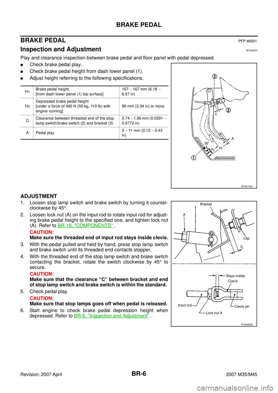
Play and clearance inspection between brake pedal and floor panel with pedal depressed.
�Check brake pedal play.
�Check brake pedal height from dash lower panel (1).
�Adjust height referring to the following specifications.
ADJUSTMENT
1. Loosen stop lamp switch and brake switch by turning it counter-
clockwise by 45°.
2. Loosen lock nut (A) on the input rod to rotate input rod for adjust-
ing brake pedal height to the specified one, and tighten lock nut
(A). Refer to BR-18, "
COMPONENTS" .
CAUTION:
Make sure the threaded end of input rod stays inside clevis.
3. With the pedal pulled and held by hand, press stop lamp switch
and brake switch until its threaded end contacts stopper.
4. With the threaded end of the stop lamp switch and brake switch
contacting the bracket, rotate the switch clockwise by 45° to
secure.
CAUTION:
Make sure that the clearance “C” between bracket and end
of stop lamp switch and brake switch is within the standard.
5. Check pedal play.
CAUTION:
Make sure that stop lamps goes off when pedal is released.
6. Start engine to check brake pedal depression height when
depressed. Refer to BR-6, "
Inspection and Adjustment" .
H1Brake pedal height
[from dash lower panel (1) top surface]157 − 167 mm (6.18 −
6.57 in)
H
2
Depressed brake pedal height
[under a force of 490 N (50 kg, 110 lb) with
engine running]90 mm (3.54 in) or more
CClearance between threaded end of the stop
lamp switch/brake switch (2) and bracket (3)0.74 − 1.96 mm (0.0291 −
0.0772 in)
A Pedal play3 − 11 mm (0.12 − 0.43
in)
SFIA2743J
PFIA0824E
Page 1275 of 4647
BR-8
BRAKE PEDAL
Revision: 2007 April2007 M35/M45
REMOVAL
1. Remove instrument driver lower panel. Refer to IP-10, "INSTRUMENT PANEL ASSEMBLY" .
2. Remove steering column assembly. Refer to PS-13, "
STEERING COLUMN" .
3. Disconnect stop lamp switch and brake switch connector.
4. Remove stop lamp switch and brake switch from brake pedal assembly.
5. Disconnect brake pedal stroke sensor connector.(With pre-crash seat belt)
CAUTION:
Brake pedal stroke sensor is not detachable. Do not detach it.
6. Remove snap pin and clevis pin from clevis of brake booster.
7. Remove brake pedal assembly mounting nuts. Pull brake booster toward engine room to the extent that
does not deform brake tube.
8. Remove brake booster clevis from input rod.
9. Remove mounting bolt and then remove brake pedal assembly from vehicle.
INSPECTION AFTER REMOVAL
�Check the items below. If any is found, replace brake pedal
assembly.
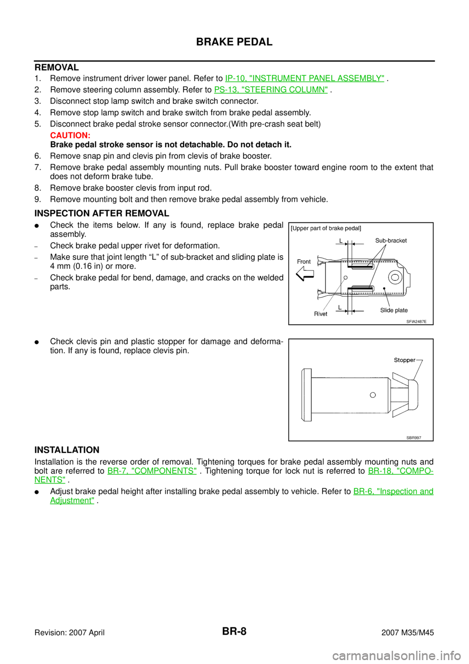
–Check brake pedal upper rivet for deformation.
–Make sure that joint length “L” of sub-bracket and sliding plate is
4 mm (0.16 in) or more.
–Check brake pedal for bend, damage, and cracks on the welded
parts.
�Check clevis pin and plastic stopper for damage and deforma-
tion. If any is found, replace clevis pin.
INSTALLATION
Installation is the reverse order of removal. Tightening torques for brake pedal assembly mounting nuts and
bolt are referred to BR-7, "
COMPONENTS" . Tightening torque for lock nut is referred to BR-18, "COMPO-
NENTS" .
�Adjust brake pedal height after installing brake pedal assembly to vehicle. Refer to BR-6, "Inspection and
Adjustment" .
SFIA2487E
SBR997