Page 3066 of 4647
SIDE OIL SEAL
FFD-11
C
E
F
G
H
I
J
K
L
MA
B
FFD
Revision: 2007 April2007 M35/M45
SIDE OIL SEALPFP:33142
Removal and InstallationNDS000ET
NOTE:
Left side oil seal is attached to engine assembly. Replace it after removing front final drive assembly
from vehicle.
REMOVAL
Right Side:
1. Remove the front drive shaft. Refer to FAX-11, "Removal and Installation" .
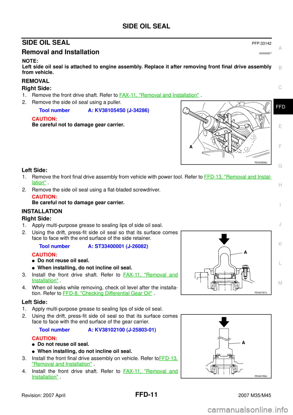
2. Remove the side oil seal using a puller.
CAUTION:
Be careful not to damage gear carrier.
Left Side:
1. Remove the front final drive assembly from vehicle with power tool. Refer to FFD-13, "Removal and Instal-
lation" .
2. Remove the side oil seal using a flat-bladed screwdriver.
CAUTION:
Be careful not to damage gear carrier.
INSTALLATION
Right Side:
1. Apply multi-purpose grease to sealing lips of side oil seal.
2. Using the drift, press-fit side oil seal so that its surface comes
face to face with the end surface of the side retainer.
CAUTION:
�Do not reuse oil seal.
�When installing, do not incline oil seal.
3. Install the front drive shaft. Refer to FAX-11, "
Removal and
Installation" .
4. When oil leaks while removing, check oil level after the installa-
tion. Refer to FFD-8, "
Checking Differential Gear Oil" .
Left Side:
1. Apply multi-purpose grease to sealing lips of side oil seal.
2. Using the drift, press-fit side oil seal so that its surface comes
face to face with the end surface of the gear carrier.
CAUTION:
�Do not reuse oil seal.
�When installing, do not incline oil seal.
3. Install the front final drive assembly on vehicle. Refer toFFD-13,
"Removal and Installation" .
4. Install the front drive shaft. Refer to FAX-11, "
Removal and
Installation" . Tool number A: KV381054S0 (J-34286)
PDIA0838J
Tool number A: ST33400001 (J-26082)
PDIA0787J
Tool number A: KV38102100 (J-25803-01)
PDIA0788J
Page 3067 of 4647
FFD-12
SIDE OIL SEAL
Revision: 2007 April2007 M35/M45
5. When oil leaks while removing, check oil level after the installation. Refer to FFD-8, "Checking Differential
Gear Oil" .
Page 3069 of 4647
FFD-14
FRONT FINAL DRIVE ASSEMBLY
Revision: 2007 April2007 M35/M45
15. Remove front final drive assembly with power tool.
INSTALLATION
Note the following, and installation is in the reverse order of removal.
�Refer to FFD-13, "COMPONENTS" about each tightening torque.
�When installing the side shaft, apply multi-purpose grease to contact surface of side shaft and side shaft
oil seal.
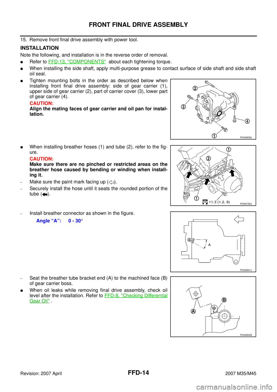
�Tighten mounting bolts in the order as described below when
installing front final drive assembly: side of gear carrier (1),
upper side of gear carrier (2), part of carrier cover (3), lower part
of gear carrier (4).
CAUTION:
Align the mating faces of gear carrier and oil pan for instal-
lation.
�When installing breather hoses (1) and tube (2), refer to the fig-
ure.
CAUTION:
Make sure there are no pinched or restricted areas on the
breather hose caused by bending or winding when install-
ing it.
–Make sure the paint mark facing up ( ).
–Securely install the hose until it seats the rounded portion of the
tube ( ).
–Install breather connector as shown in the figure.
–Seat the breather tube bracket end (A) to the machined face (B)
of gear carrier boss.
�When oil leaks while removing final drive assembly, check oil
level after the installation. Refer to FFD-8, "
Checking Differential
Gear Oil" .
PDIA0839J
PDIA0790J
Angle “A”: 0 - 30°
PDIA0841J
PDIA0842E
Page 3070 of 4647
FRONT FINAL DRIVE ASSEMBLY
FFD-15
C
E
F
G
H
I
J
K
L
MA
B
FFD
Revision: 2007 April2007 M35/M45
Disassembly and AssemblyNDS000EV
COMPONENTS
1. Drive pinion lock nut 2. Companion flange 3. Front oil seal
4. Pinion front bearing 5. Drive pinion bearing adjusting
washer6. Drive pinion adjusting washer
7. Gear carrier 8. Pinion rear bearing 9. Pinion height adjusting washer
10. Drive pinion 11. Drive gear 12. Side oil seal (right side)
13. Side retainer 14. O-ring 15. Side bearing adjusting shim
16. Side bearing 17. Differential case 18. Breather connector
19. Dowel pin 20. Filler plug 21. Drain plug
22. Gasket 23. Carrier cover 24. Gear oil defence
25. Side gear thrust washer 26. Side gear 27. Circular clip
28. Pinion mate thrust washer 29. Pinion mate gear 30. Pinion mate shaft
31. Lock pin 32. Side bearing adjusting washer 33. Side oil seal (left side)
PDIA0791J
Page 3071 of 4647
FFD-16
FRONT FINAL DRIVE ASSEMBLY
Revision: 2007 April2007 M35/M45
ASSEMBLY INSPECTION AND ADJUSTMENT
�Before inspection and adjustment, drain gear oil.
Total Preload Torque
1. Rotate drive pinion back and forth 2 to 3 times to check for unusual noise and rotation malfunction.
2. Rotate drive pinion at least 20 times to check for smooth opera-
tion of the bearing.
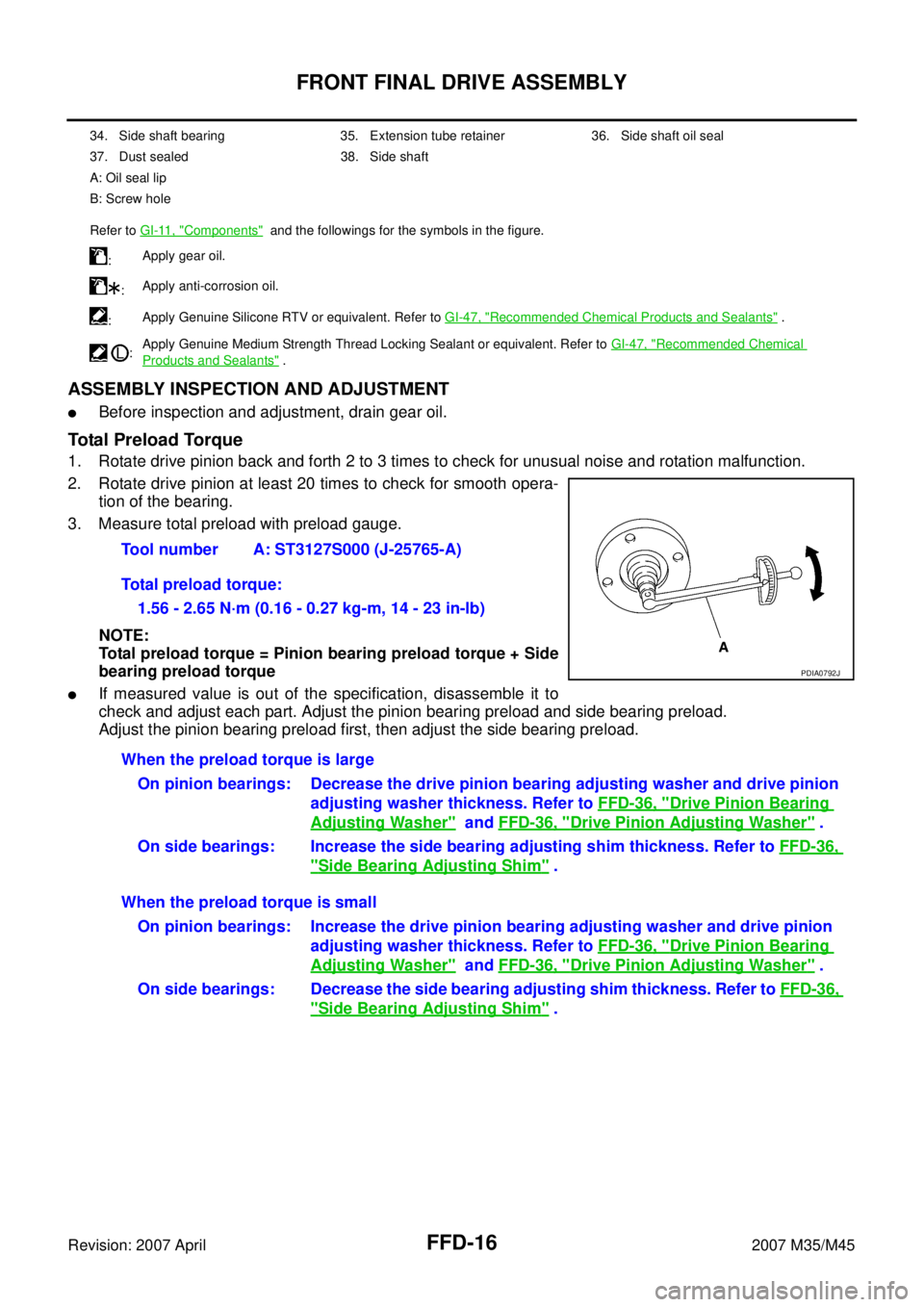
3. Measure total preload with preload gauge.
NOTE:
Total preload torque = Pinion bearing preload torque + Side
bearing preload torque
�If measured value is out of the specification, disassemble it to
check and adjust each part. Adjust the pinion bearing preload and side bearing preload.
Adjust the pinion bearing preload first, then adjust the side bearing preload.
34. Side shaft bearing 35. Extension tube retainer 36. Side shaft oil seal
37. Dust sealed 38. Side shaft
A: Oil seal lip
B: Screw hole
Refer to GI-11, "
Components" and the followings for the symbols in the figure.
:Apply gear oil.
:Apply anti-corrosion oil.
:Apply Genuine Silicone RTV or equivalent. Refer to GI-47, "
Recommended Chemical Products and Sealants" .
:Apply Genuine Medium Strength Thread Locking Sealant or equivalent. Refer to GI-47, "
Recommended Chemical
Products and Sealants" .
Tool number A: ST3127S000 (J-25765-A)
Total preload torque:
1.56 - 2.65 N·m (0.16 - 0.27 kg-m, 14 - 23 in-lb)
PDIA0792J
When the preload torque is large
On pinion bearings: Decrease the drive pinion bearing adjusting washer and drive pinion
adjusting washer thickness. Refer to FFD-36, "
Drive Pinion Bearing
Adjusting Washer" and FFD-36, "Drive Pinion Adjusting Washer" .
On side bearings: Increase the side bearing adjusting shim thickness. Refer to FFD-36,
"Side Bearing Adjusting Shim" .
When the preload torque is small
On pinion bearings: Increase the drive pinion bearing adjusting washer and drive pinion
adjusting washer thickness. Refer to FFD-36, "
Drive Pinion Bearing
Adjusting Washer" and FFD-36, "Drive Pinion Adjusting Washer" .
On side bearings: Decrease the side bearing adjusting shim thickness. Refer to FFD-36,
"Side Bearing Adjusting Shim" .
Page 3075 of 4647
FFD-20
FRONT FINAL DRIVE ASSEMBLY
Revision: 2007 April2007 M35/M45
c. If the runout value is still outside of the limit after the check and repair, replace companion flange.
DISASSEMBLY
Side Shaft Assembly
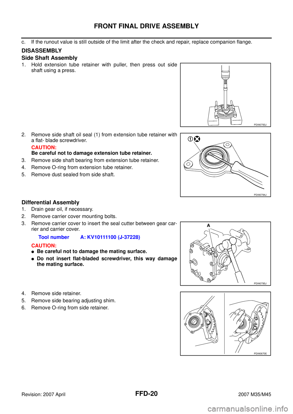
1. Hold extension tube retainer with puller, then press out side
shaft using a press.
2. Remove side shaft oil seal (1) from extension tube retainer with
a flat- blade screwdriver.
CAUTION:
Be careful not to damage extension tube retainer.
3. Remove side shaft bearing from extension tube retainer.
4. Remove O-ring from extension tube retainer.
5. Remove dust sealed from side shaft.
Differential Assembly
1. Drain gear oil, if necessary.
2. Remove carrier cover mounting bolts.
3. Remove carrier cover to insert the seal cutter between gear car-
rier and carrier cover.
CAUTION:
�Be careful not to damage the mating surface.
�Do not insert flat-bladed screwdriver, this way damage
the mating surface.
4. Remove side retainer.
5. Remove side bearing adjusting shim.
6. Remove O-ring from side retainer.
PDIA0793J
PDIA0794J
Tool number A: KV10111100 (J-37228)
PDIA0795J
PDIA0670E
Page 3076 of 4647
FRONT FINAL DRIVE ASSEMBLY
FFD-21
C
E
F
G
H
I
J
K
L
MA
B
FFD
Revision: 2007 April2007 M35/M45
7. Remove differential case assembly from gear carrier.
8. Remove side oil seal (right side) from side retainer.
9. Remove side bearing outer race with puller.
10. Remove O-ring from gear carrier.
11. Remove side oil seal (left side) from gear carrier.
12. Remove side bearing outer race with puller.
PDIA0671E
PDIA0672E
Tool number A: KV381054S0 (J-34286)
PDIA0796J
Tool number A: KV381054S0 (J-34286)
PDIA0797J
Page 3079 of 4647
FFD-24
FRONT FINAL DRIVE ASSEMBLY
Revision: 2007 April2007 M35/M45
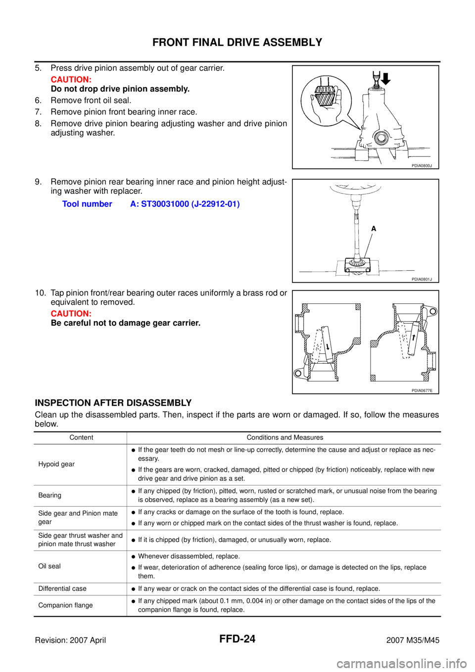
5. Press drive pinion assembly out of gear carrier.
CAUTION:
Do not drop drive pinion assembly.
6. Remove front oil seal.
7. Remove pinion front bearing inner race.
8. Remove drive pinion bearing adjusting washer and drive pinion
adjusting washer.
9. Remove pinion rear bearing inner race and pinion height adjust-
ing washer with replacer.
10. Tap pinion front/rear bearing outer races uniformly a brass rod or
equivalent to removed.
CAUTION:
Be careful not to damage gear carrier.
INSPECTION AFTER DISASSEMBLY
Clean up the disassembled parts. Then, inspect if the parts are worn or damaged. If so, follow the measures
below.
PDIA0800J
Tool number A: ST30031000 (J-22912-01)
PDIA0801J
PDIA0677E
Content Conditions and Measures
Hypoid gear
�If the gear teeth do not mesh or line-up correctly, determine the cause and adjust or replace as nec-
essary.
�If the gears are worn, cracked, damaged, pitted or chipped (by friction) noticeably, replace with new
drive gear and drive pinion as a set.
Bearing
�If any chipped (by friction), pitted, worn, rusted or scratched mark, or unusual noise from the bearing
is observed, replace as a bearing assembly (as a new set).
Side gear and Pinion mate
gear
�If any cracks or damage on the surface of the tooth is found, replace.
�If any worn or chipped mark on the contact sides of the thrust washer is found, replace.
Side gear thrust washer and
pinion mate thrust washer
�If it is chipped (by friction), damaged, or unusually worn, replace.
Oil seal
�Whenever disassembled, replace.
�If wear, deterioration of adherence (sealing force lips), or damage is detected on the lips, replace
them.
Differential case
�If any wear or crack on the contact sides of the differential case is found, replace.
Companion flange
�If any chipped mark (about 0.1 mm, 0.004 in) or other damage on the contact sides of the lips of the
companion flange is found, replace.