2007 INFINITI M35 component
[x] Cancel search: componentPage 1534 of 4647
EC-5
C
D
E
F
G
H
I
J
K
L
M
ECA
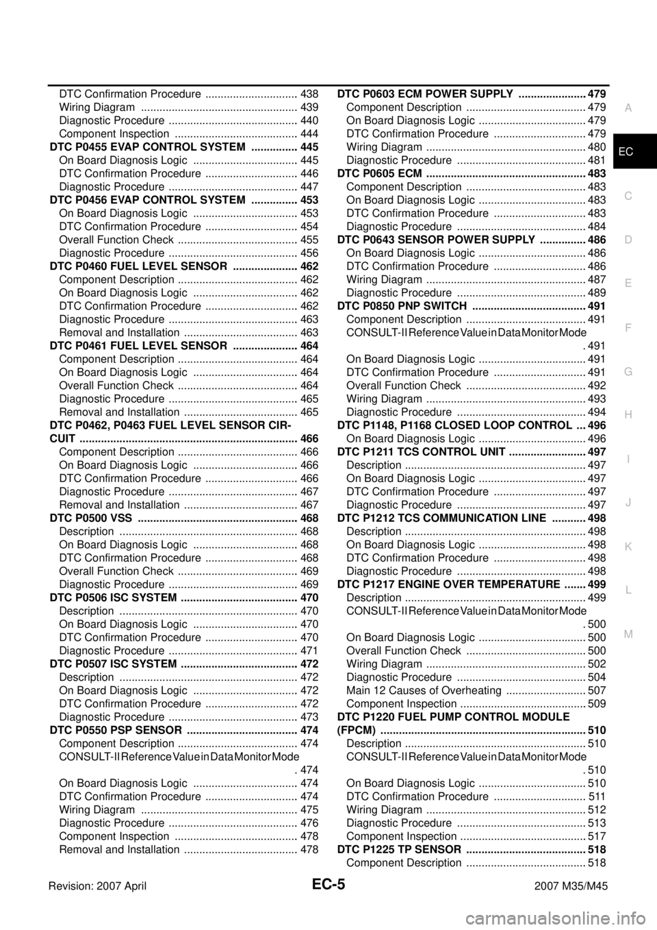
Revision: 2007 April2007 M35/M45 DTC Confirmation Procedure ............................... 438
Wiring Diagram .................................................... 439
Diagnostic Procedure ........................................... 440
Component Inspection ......................................... 444
DTC P0455 EVAP CONTROL SYSTEM ................ 445
On Board Diagnosis Logic ................................... 445
DTC Confirmation Procedure ............................... 446
Diagnostic Procedure ........................................... 447
DTC P0456 EVAP CONTROL SYSTEM ................ 453
On Board Diagnosis Logic ................................... 453
DTC Confirmation Procedure ............................... 454
Overall Function Check ........................................ 455
Diagnostic Procedure ........................................... 456
DTC P0460 FUEL LEVEL SENSOR ...................... 462
Component Description ........................................ 462
On Board Diagnosis Logic ................................... 462
DTC Confirmation Procedure ............................... 462
Diagnostic Procedure ........................................... 463
Removal and Installation ...................................... 463
DTC P0461 FUEL LEVEL SENSOR ...................... 464
Component Description ........................................ 464
On Board Diagnosis Logic ................................... 464
Overall Function Check ........................................ 464
Diagnostic Procedure ........................................... 465
Removal and Installation ...................................... 465
DTC P0462, P0463 FUEL LEVEL SENSOR CIR-
CUIT ........................................................................ 466
Component Description ........................................ 466
On Board Diagnosis Logic ................................... 466
DTC Confirmation Procedure ............................... 466
Diagnostic Procedure ........................................... 467
Removal and Installation ...................................... 467
DTC P0500 VSS ..................................................... 468
Description ........................................................... 468
On Board Diagnosis Logic ................................... 468
DTC Confirmation Procedure ............................... 468
Overall Function Check ........................................ 469
Diagnostic Procedure ........................................... 469
DTC P0506 ISC SYSTEM ....................................... 470
Description ........................................................... 470
On Board Diagnosis Logic ................................... 470
DTC Confirmation Procedure ............................... 470
Diagnostic Procedure ........................................... 471
DTC P0507 ISC SYSTEM ....................................... 472
Description ........................................................... 472
On Board Diagnosis Logic ................................... 472
DTC Confirmation Procedure ............................... 472
Diagnostic Procedure ........................................... 473
DTC P0550 PSP SENSOR ..................................... 474
Component Description ........................................ 474
CONSULT-II Reference Value in Data Monitor Mode
. 474
On Board Diagnosis Logic ................................... 474
DTC Confirmation Procedure ............................... 474
Wiring Diagram .................................................... 475
Diagnostic Procedure ........................................... 476
Component Inspection ......................................... 478
Removal and Installation ...................................... 478DTC P0603 ECM POWER SUPPLY .......................479
Component Description ........................................479
On Board Diagnosis Logic ....................................479
DTC Confirmation Procedure ...............................479
Wiring Diagram .....................................................480
Diagnostic Procedure ...........................................481
DTC P0605 ECM .....................................................483
Component Description ........................................483
On Board Diagnosis Logic ....................................483
DTC Confirmation Procedure ...............................483
Diagnostic Procedure ...........................................484
DTC P0643 SENSOR POWER SUPPLY ................486
On Board Diagnosis Logic ....................................486
DTC Confirmation Procedure ...............................486
Wiring Diagram .....................................................487
Diagnostic Procedure ...........................................489
DTC P0850 PNP SWITCH ......................................491
Component Description ........................................491
CONSULT-II Reference Value in Data Monitor Mode
.491
On Board Diagnosis Logic ....................................491
DTC Confirmation Procedure ...............................491
Overall Function Check ........................................492
Wiring Diagram .....................................................493
Diagnostic Procedure ...........................................494
DTC P1148, P1168 CLOSED LOOP CONTROL ....496
On Board Diagnosis Logic ....................................496
DTC P1211 TCS CONTROL UNIT ..........................497
Description ............................................................497
On Board Diagnosis Logic ....................................497
DTC Confirmation Procedure ...............................497
Diagnostic Procedure ...........................................497
DTC P1212 TCS COMMUNICATION LINE ............498
Description ............................................................498
On Board Diagnosis Logic ....................................498
DTC Confirmation Procedure ...............................498
Diagnostic Procedure ...........................................498
DTC P1217 ENGINE OVER TEMPERATURE ........499
Description ............................................................499
CONSULT-II Reference Value in Data Monitor Mode
.500
On Board Diagnosis Logic ....................................500
Overall Function Check ........................................500
Wiring Diagram .....................................................502
Diagnostic Procedure ...........................................504
Main 12 Causes of Overheating ...........................507
Component Inspection ..........................................509
DTC P1220 FUEL PUMP CONTROL MODULE
(FPCM) ....................................................................510
Description ............................................................510
CONSULT-II Reference Value in Data Monitor Mode
.510
On Board Diagnosis Logic ....................................510
DTC Confirmation Procedure ...............................511
Wiring Diagram .....................................................512
Diagnostic Procedure ...........................................513
Component Inspection ..........................................517
DTC P1225 TP SENSOR ........................................518
Component Description ........................................518
Page 1535 of 4647

EC-6Revision: 2007 April2007 M35/M45 On Board Diagnosis Logic ....................................518
DTC Confirmation Procedure ...............................518
Diagnostic Procedure ...........................................519
Removal and Installation ......................................519
DTC P1226 TP SENSOR ........................................520
Component Description ........................................520
On Board Diagnosis Logic ....................................520
DTC Confirmation Procedure ...............................520
Diagnostic Procedure ...........................................521
Removal and Installation ......................................521
DTC P1421 COLD START CONTROL ...................522
Description ............................................................522
On Board Diagnosis Logic ....................................522
DTC Confirmation Procedure ...............................522
Diagnostic Procedure ...........................................522
DTC P1550 BATTERY CURRENT SENSOR ..........524
Component Description ........................................524
CONSULT-II Reference Value in Data Monitor Mode
.524
On Board Diagnosis Logic ....................................524
DTC Confirmation Procedure ...............................525
Wiring Diagram .....................................................526
Diagnostic Procedure ...........................................527
Component Inspection ..........................................529
DTC P1551, P1552 BATTERY CURRENT SENSOR .531
Component Description ........................................531
CONSULT-II Reference Value in Data Monitor Mode
.531
On Board Diagnosis Logic ....................................531
DTC Confirmation Procedure ...............................532
Wiring Diagram .....................................................533
Diagnostic Procedure ...........................................534
Component Inspection ..........................................536
DTC P1553 BATTERY CURRENT SENSOR ..........538
Component Description ........................................538
CONSULT-II Reference Value in Data Monitor Mode
.538
On Board Diagnosis Logic ....................................538
DTC Confirmation Procedure ...............................539
Wiring Diagram .....................................................540
Diagnostic Procedure ...........................................541
Component Inspection ..........................................543
DTC P1554 BATTERY CURRENT SENSOR ..........545
Component Description ........................................545
CONSULT-II Reference Value in Data Monitor Mode
.545
On Board Diagnosis Logic ....................................545
Overall Function Check ........................................546
Wiring Diagram .....................................................547
Diagnostic Procedure ...........................................548
Component Inspection ..........................................550
DTC P1564 ICC STEERING SWITCH ....................552
Component Description ........................................552
CONSULT-II Reference Value in Data Monitor Mode
.552
On Board Diagnosis Logic ....................................552
DTC Confirmation Procedure ...............................553
Wiring Diagram .....................................................554Diagnostic Procedure ............................................555
Component Inspection ..........................................558
DTC P1564 ASCD STEERING SWITCH ................559
Component Description ........................................559
CONSULT-II Reference Value in Data Monitor Mode
.559
On Board Diagnosis Logic ....................................559
DTC Confirmation Procedure ................................560
Wiring Diagram .....................................................561
Diagnostic Procedure ............................................562
Component Inspection ..........................................565
DTC P1568 ICC FUNCTION ...................................566
On Board Diagnosis Logic ....................................566
DTC Confirmation Procedure ................................566
Diagnostic Procedure ............................................566
DTC P1572 ICC BRAKE SWITCH ..........................567
Component Description ........................................567
CONSULT-II Reference Value in Data Monitor Mode
.567
On Board Diagnosis Logic ....................................567
DTC Confirmation Procedure ................................568
Wiring Diagram .....................................................569
Diagnostic Procedure ............................................570
Component Inspection ..........................................575
DTC P1572 ASCD BRAKE SWITCH ......................576
Component Description ........................................576
CONSULT-II Reference Value in Data Monitor Mode
.576
On Board Diagnosis Logic ....................................576
DTC Confirmation Procedure ................................577
Wiring Diagram .....................................................578
Diagnostic Procedure ............................................579
Component Inspection ..........................................583
DTC P1574 ICC VEHICLE SPEED SENSOR .........584
Component Description ........................................584
On Board Diagnosis Logic ....................................584
DTC Confirmation Procedure ................................584
Diagnostic Procedure ............................................585
DTC P1574 ASCD VEHICLE SPEED SENSOR .....586
Component Description ........................................586
On Board Diagnosis Logic ....................................586
DTC Confirmation Procedure ................................586
Diagnostic Procedure ............................................587
DTC P1715 INPUT SPEED SENSOR (TURBINE
REVOLUTION SENSOR) ........................................588
Description ............................................................588
CONSULT-II Reference Value in Data Monitor Mode
.588
On Board Diagnosis Logic ....................................588
Diagnostic Procedure ............................................588
DTC P1805 BRAKE SWITCH .................................589
Component Description ........................................589
CONSULT-II Reference Value in Data Monitor Mode
.589
On Board Diagnosis Logic ....................................589
DTC Confirmation Procedure ................................590
Wiring Diagram .....................................................591
Diagnostic Procedure ............................................592
Component Inspection .........................................
Page 1536 of 4647
EC-7
C
D
E
F
G
H
I
J
K
L
M
ECA
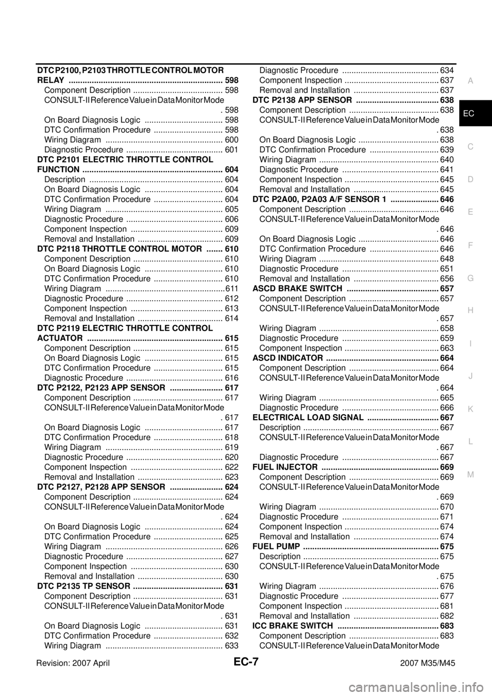
Revision: 2007 April2007 M35/M45 DTC P2100, P2103 THROTTLE CONTROL MOTOR
RELAY .................................................................... 598
Component Description ........................................ 598
CONSULT-II Reference Value in Data Monitor Mode
. 598
On Board Diagnosis Logic ................................... 598
DTC Confirmation Procedure ............................... 598
Wiring Diagram .................................................... 600
Diagnostic Procedure ........................................... 601
DTC P2101 ELECTRIC THROTTLE CONTROL
FUNCTION .............................................................. 604
Description ........................................................... 604
On Board Diagnosis Logic ................................... 604
DTC Confirmation Procedure ............................... 604
Wiring Diagram .................................................... 605
Diagnostic Procedure ........................................... 606
Component Inspection ......................................... 609
Removal and Installation ...................................... 609
DTC P2118 THROTTLE CONTROL MOTOR ........ 610
Component Description ........................................ 610
On Board Diagnosis Logic ................................... 610
DTC Confirmation Procedure ............................... 610
Wiring Diagram ..................................................... 611
Diagnostic Procedure ........................................... 612
Component Inspection ......................................... 613
Removal and Installation ...................................... 614
DTC P2119 ELECTRIC THROTTLE CONTROL
ACTUATOR ............................................................ 615
Component Description ........................................ 615
On Board Diagnosis Logic ................................... 615
DTC Confirmation Procedure ............................... 615
Diagnostic Procedure ........................................... 616
DTC P2122, P2123 APP SENSOR ........................ 617
Component Description ........................................ 617
CONSULT-II Reference Value in Data Monitor Mode
. 617
On Board Diagnosis Logic ................................... 617
DTC Confirmation Procedure ............................... 618
Wiring Diagram .................................................... 619
Diagnostic Procedure ........................................... 620
Component Inspection ......................................... 622
Removal and Installation ...................................... 623
DTC P2127, P2128 APP SENSOR ........................ 624
Component Description ........................................ 624
CONSULT-II Reference Value in Data Monitor Mode
. 624
On Board Diagnosis Logic ................................... 624
DTC Confirmation Procedure ............................... 625
Wiring Diagram .................................................... 626
Diagnostic Procedure ........................................... 627
Component Inspection ......................................... 630
Removal and Installation ...................................... 630
DTC P2135 TP SENSOR ........................................ 631
Component Description ........................................ 631
CONSULT-II Reference Value in Data Monitor Mode
. 631
On Board Diagnosis Logic ................................... 631
DTC Confirmation Procedure ............................... 632
Wiring Diagram .................................................... 633Diagnostic Procedure ...........................................634
Component Inspection ..........................................637
Removal and Installation ......................................637
DTC P2138 APP SENSOR .....................................638
Component Description ........................................638
CONSULT-II Reference Value in Data Monitor Mode
.638
On Board Diagnosis Logic ....................................638
DTC Confirmation Procedure ...............................639
Wiring Diagram .....................................................640
Diagnostic Procedure ...........................................641
Component Inspection ..........................................645
Removal and Installation ......................................645
DTC P2A00, P2A03 A/F SENSOR 1 ......................646
Component Description ........................................646
CONSULT-II Reference Value in Data Monitor Mode
.646
On Board Diagnosis Logic ....................................646
DTC Confirmation Procedure ...............................646
Wiring Diagram .....................................................648
Diagnostic Procedure ...........................................651
Removal and Installation ......................................656
ASCD BRAKE SWITCH .........................................657
Component Description ........................................657
CONSULT-II Reference Value in Data Monitor Mode
.657
Wiring Diagram .....................................................658
Diagnostic Procedure ...........................................659
Component Inspection ..........................................663
ASCD INDICATOR ..................................................664
Component Description ........................................664
CONSULT-II Reference Value in Data Monitor Mode
.664
Wiring Diagram .....................................................665
Diagnostic Procedure ...........................................666
ELECTRICAL LOAD SIGNAL ................................667
Description ............................................................667
CONSULT-II Reference Value in Data Monitor Mode
.667
Diagnostic Procedure ...........................................667
FUEL INJECTOR ....................................................669
Component Description ........................................669
CONSULT-II Reference Value in Data Monitor Mode
.669
Wiring Diagram .....................................................670
Diagnostic Procedure ...........................................671
Component Inspection ..........................................674
Removal and Installation ......................................674
FUEL PUMP ............................................................675
Description ............................................................675
CONSULT-II Reference Value in Data Monitor Mode
.675
Wiring Diagram .....................................................676
Diagnostic Procedure ...........................................677
Component Inspection ..........................................681
Removal and Installation ......................................682
ICC BRAKE SWITCH .............................................683
Component Description ........................................683
CONSULT-II Reference Value in Data Monitor Mode
Page 1537 of 4647
EC-8Revision: 2007 April2007 M35/M45 .683
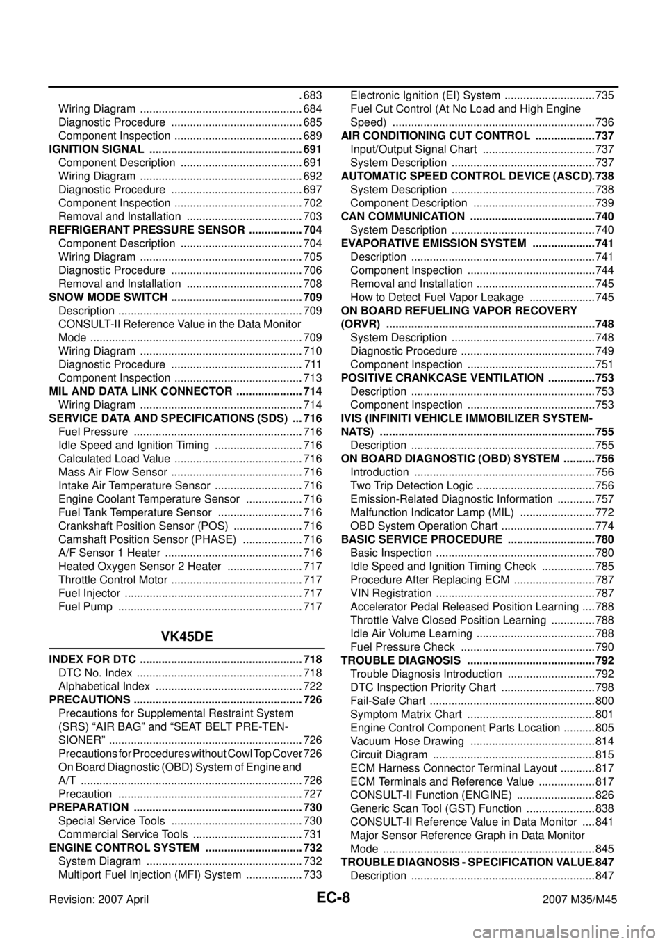
Wiring Diagram .....................................................684
Diagnostic Procedure ...........................................685
Component Inspection ..........................................689
IGNITION SIGNAL ..................................................691
Component Description ........................................691
Wiring Diagram .....................................................692
Diagnostic Procedure ...........................................697
Component Inspection ..........................................702
Removal and Installation ......................................703
REFRIGERANT PRESSURE SENSOR ..................704
Component Description ........................................704
Wiring Diagram .....................................................705
Diagnostic Procedure ...........................................706
Removal and Installation ......................................708
SNOW MODE SWITCH ...........................................709
Description ............................................................709
CONSULT-II Reference Value in the Data Monitor
Mode .....................................................................709
Wiring Diagram .....................................................710
Diagnostic Procedure ...........................................711
Component Inspection ..........................................713
MIL AND DATA LINK CONNECTOR ......................714
Wiring Diagram .....................................................714
SERVICE DATA AND SPECIFICATIONS (SDS) ....716
Fuel Pressure .......................................................716
Idle Speed and Ignition Timing .............................716
Calculated Load Value ..........................................716
Mass Air Flow Sensor ...........................................716
Intake Air Temperature Sensor .............................716
Engine Coolant Temperature Sensor ...................716
Fuel Tank Temperature Sensor ............................716
Crankshaft Position Sensor (POS) .......................716
Camshaft Position Sensor (PHASE) ....................716
A/F Sensor 1 Heater .............................................716
Heated Oxygen Sensor 2 Heater .........................717
Throttle Control Motor ...........................................717
Fuel Injector ..........................................................717
Fuel Pump ............................................................717
VK45DE
INDEX FOR DTC .....................................................718
DTC No. Index ......................................................718
Alphabetical Index ................................................722
PRECAUTIONS .......................................................726
Precautions for Supplemental Restraint System
(SRS) “AIR BAG” and “SEAT BELT PRE-TEN-
SIONER” ...............................................................726
Precautions for Procedures without Cowl Top Cover .726
On Board Diagnostic (OBD) System of Engine and
A/T ........................................................................726
Precaution ............................................................727
PREPARATION .......................................................730
Special Service Tools ...........................................730
Commercial Service Tools ....................................731
ENGINE CONTROL SYSTEM ................................732
System Diagram ...................................................732
Multiport Fuel Injection (MFI) System ...................733Electronic Ignition (EI) System ..............................735
Fuel Cut Control (At No Load and High Engine
Speed) ..................................................................736
AIR CONDITIONING CUT CONTROL ....................737
Input/Output Signal Chart .....................................737
System Description ...............................................737
AUTOMATIC SPEED CONTROL DEVICE (ASCD) .738
System Description ...............................................738
Component Description ........................................739
CAN COMMUNICATION .........................................740
System Description ...............................................740
EVAPORATIVE EMISSION SYSTEM .....................741
Description ............................................................741
Component Inspection ..........................................744
Removal and Installation .......................................745
How to Detect Fuel Vapor Leakage ......................745
ON BOARD REFUELING VAPOR RECOVERY
(ORVR) ....................................................................748
System Description ...............................................748
Diagnostic Procedure ............................................749
Component Inspection ..........................................751
POSITIVE CRANKCASE VENTILATION ................753
Description ............................................................753
Component Inspection ..........................................753
IVIS (INFINITI VEHICLE IMMOBILIZER SYSTEM-
NATS) ......................................................................755
Description ............................................................755
ON BOARD DIAGNOSTIC (OBD) SYSTEM ...........756
Introduction ...........................................................756
Two Trip Detection Logic .......................................756
Emission-Related Diagnostic Information .............757
Malfunction Indicator Lamp (MIL) .........................772
OBD System Operation Chart ...............................774
BASIC SERVICE PROCEDURE .............................780
Basic Inspection ....................................................780
Idle Speed and Ignition Timing Check ..................785
Procedure After Replacing ECM ...........................787
VIN Registration ....................................................787
Accelerator Pedal Released Position Learning .....788
Throttle Valve Closed Position Learning ...............788
Idle Air Volume Learning .......................................788
Fuel Pressure Check ............................................790
TROUBLE DIAGNOSIS ..........................................792
Trouble Diagnosis Introduction .............................792
DTC Inspection Priority Chart ...............................798
Fail-Safe Chart ......................................................800
Symptom Matrix Chart ..........................................801
Engine Control Component Parts Location ...........805
Vacuum Hose Drawing .........................................814
Circuit Diagram .....................................................815
ECM Harness Connector Terminal Layout ............817
ECM Terminals and Reference Value ...................817
CONSULT-II Function (ENGINE) ..........................826
Generic Scan Tool (GST) Function .......................838
CONSULT-II Reference Value in Data Monitor .....841
Major Sensor Reference Graph in Data Monitor
Mode .....................................................................845
TROUBLE DIAGNOSIS - SPECIFICATION VALUE .847
Description ............................................................847
Page 1538 of 4647
EC-9
C
D
E
F
G
H
I
J
K
L
M
ECA
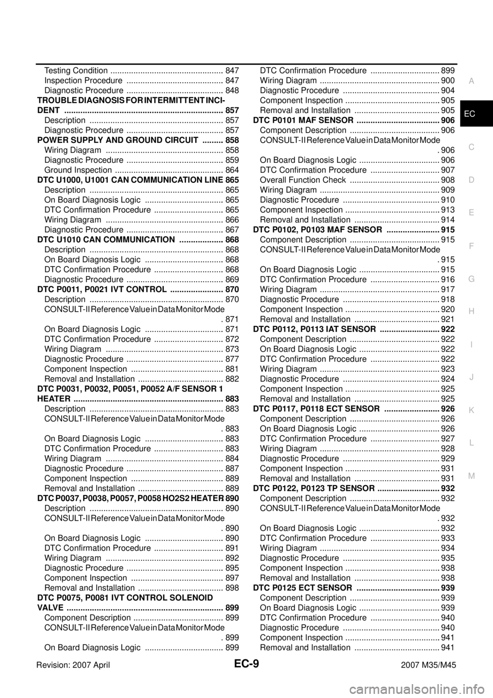
Revision: 2007 April2007 M35/M45 Testing Condition .................................................. 847
Inspection Procedure ........................................... 847
Diagnostic Procedure ........................................... 848
TROUBLE DIAGNOSIS FOR INTERMITTENT INCI-
DENT ...................................................................... 857
Description ........................................................... 857
Diagnostic Procedure ........................................... 857
POWER SUPPLY AND GROUND CIRCUIT .......... 858
Wiring Diagram .................................................... 858
Diagnostic Procedure ........................................... 859
Ground Inspection ................................................ 864
DTC U1000, U1001 CAN COMMUNICATION LINE . 865
Description ........................................................... 865
On Board Diagnosis Logic ................................... 865
DTC Confirmation Procedure ............................... 865
Wiring Diagram .................................................... 866
Diagnostic Procedure ........................................... 867
DTC U1010 CAN COMMUNICATION .................... 868
Description ........................................................... 868
On Board Diagnosis Logic ................................... 868
DTC Confirmation Procedure ............................... 868
Diagnostic Procedure ........................................... 869
DTC P0011, P0021 IVT CONTROL ........................ 870
Description ........................................................... 870
CONSULT-II Reference Value in Data Monitor Mode
. 871
On Board Diagnosis Logic ................................... 871
DTC Confirmation Procedure ............................... 872
Wiring Diagram .................................................... 873
Diagnostic Procedure ........................................... 877
Component Inspection ......................................... 881
Removal and Installation ...................................... 882
DTC P0031, P0032, P0051, P0052 A/F SENSOR 1
HEATER .................................................................. 883
Description ........................................................... 883
CONSULT-II Reference Value in Data Monitor Mode
. 883
On Board Diagnosis Logic ................................... 883
DTC Confirmation Procedure ............................... 883
Wiring Diagram .................................................... 884
Diagnostic Procedure ........................................... 887
Component Inspection ......................................... 889
Removal and Installation ...................................... 889
DTC P0037, P0038, P0057, P0058 HO2S2 HEATER . 890
Description ........................................................... 890
CONSULT-II Reference Value in Data Monitor Mode
. 890
On Board Diagnosis Logic ................................... 890
DTC Confirmation Procedure ............................... 891
Wiring Diagram .................................................... 892
Diagnostic Procedure ........................................... 895
Component Inspection ......................................... 897
Removal and Installation ...................................... 898
DTC P0075, P0081 IVT CONTROL SOLENOID
VALVE ..................................................................... 899
Component Description ........................................ 899
CONSULT-II Reference Value in Data Monitor Mode
. 899
On Board Diagnosis Logic ................................... 899DTC Confirmation Procedure ...............................899
Wiring Diagram .....................................................900
Diagnostic Procedure ...........................................904
Component Inspection ..........................................905
Removal and Installation ......................................905
DTC P0101 MAF SENSOR .....................................906
Component Description ........................................906
CONSULT-II Reference Value in Data Monitor Mode
.906
On Board Diagnosis Logic ....................................906
DTC Confirmation Procedure ...............................907
Overall Function Check ........................................908
Wiring Diagram .....................................................909
Diagnostic Procedure ...........................................910
Component Inspection ..........................................913
Removal and Installation ......................................914
DTC P0102, P0103 MAF SENSOR ........................915
Component Description ........................................915
CONSULT-II Reference Value in Data Monitor Mode
.915
On Board Diagnosis Logic ....................................915
DTC Confirmation Procedure ...............................916
Wiring Diagram .....................................................917
Diagnostic Procedure ...........................................918
Component Inspection ..........................................920
Removal and Installation ......................................921
DTC P0112, P0113 IAT SENSOR ...........................922
Component Description ........................................922
On Board Diagnosis Logic ....................................922
DTC Confirmation Procedure ...............................922
Wiring Diagram .....................................................923
Diagnostic Procedure ...........................................924
Component Inspection ..........................................925
Removal and Installation ......................................925
DTC P0117, P0118 ECT SENSOR .........................926
Component Description ........................................926
On Board Diagnosis Logic ....................................926
DTC Confirmation Procedure ...............................927
Wiring Diagram .....................................................928
Diagnostic Procedure ...........................................929
Component Inspection ..........................................931
Removal and Installation ......................................931
DTC P0122, P0123 TP SENSOR ............................932
Component Description ........................................932
CONSULT-II Reference Value in Data Monitor Mode
.932
On Board Diagnosis Logic ....................................932
DTC Confirmation Procedure ...............................933
Wiring Diagram .....................................................934
Diagnostic Procedure ...........................................935
Component Inspection ..........................................938
Removal and Installation ......................................938
DTC P0125 ECT SENSOR .....................................939
Component Description ........................................939
On Board Diagnosis Logic ....................................939
DTC Confirmation Procedure ...............................940
Diagnostic Procedure ...........................................940
Component Inspection ..........................................941
Removal and Installation ......................................941
Page 1539 of 4647

EC-10Revision: 2007 April2007 M35/M45 DTC P0127 IAT SENSOR .......................................942
Component Description ........................................942
On Board Diagnosis Logic ....................................942
DTC Confirmation Procedure ...............................942
Diagnostic Procedure ...........................................943
Component Inspection ..........................................944
Removal and Installation ......................................944
DTC P0128 THERMOSTAT FUNCTION .................945
On Board Diagnosis Logic ....................................945
DTC Confirmation Procedure ...............................945
Diagnostic Procedure ...........................................945
Component Inspection ..........................................946
Removal and Installation ......................................946
DTC P0130, P0150 A/F SENSOR 1 ........................947
Component Description ........................................947
CONSULT-II Reference Value in Data Monitor Mode
.947
On Board Diagnosis Logic ....................................947
DTC Confirmation Procedure ...............................947
Overall Function Check ........................................949
Wiring Diagram .....................................................950
Diagnostic Procedure ...........................................953
Removal and Installation ......................................956
DTC P0131, P0151 A/F SENSOR 1 ........................957
Component Description ........................................957
CONSULT-II Reference Value in Data Monitor Mode
.957
On Board Diagnosis Logic ....................................957
DTC Confirmation Procedure ...............................957
Wiring Diagram .....................................................959
Diagnostic Procedure ...........................................962
Removal and Installation ......................................965
DTC P0132, P0152 A/F SENSOR 1 ........................966
Component Description ........................................966
CONSULT-II Reference Value in Data Monitor Mode
.966
On Board Diagnosis Logic ....................................966
DTC Confirmation Procedure ...............................966
Wiring Diagram .....................................................968
Diagnostic Procedure ...........................................971
Removal and Installation ......................................974
DTC P0133, P0153 A/F SENSOR 1 ........................975
Component Description ........................................975
CONSULT-II Reference Value in Data Monitor Mode
.975
On Board Diagnosis Logic ....................................975
DTC Confirmation Procedure ...............................976
Wiring Diagram .....................................................978
Diagnostic Procedure ...........................................981
Removal and Installation ......................................986
DTC P0137, P0157 HO2S2 .....................................987
Component Description ........................................987
CONSULT-II Reference Value in Data Monitor Mode
.987
On Board Diagnosis Logic ....................................987
DTC Confirmation Procedure ...............................988
Overall Function Check ........................................988
Wiring Diagram .....................................................990
Diagnostic Procedure ...........................................993Component Inspection ..........................................996
Removal and Installation .......................................997
DTC P0138, P0158 HO2S2 .....................................998
Component Description ........................................998
CONSULT-II Reference Value in Data Monitor Mode
.998
On Board Diagnosis Logic ....................................998
DTC Confirmation Procedure ................................999
Overall Function Check ........................................1000
Wiring Diagram ....................................................1001
Diagnostic Procedure ...........................................1004
Component Inspection .........................................1009
Removal and Installation ......................................1010
DTC P0139, P0159 HO2S2 ....................................1011
Component Description .......................................1011
CONSULT-II Reference Value in Data Monitor Mode
1011
On Board Diagnosis Logic ...................................1011
DTC Confirmation Procedure ...............................1012
Overall Function Check ........................................1012
Wiring Diagram ....................................................1014
Diagnostic Procedure ...........................................1017
Component Inspection .........................................1020
Removal and Installation ......................................1021
DTC P0171, P0174 FUEL INJECTION SYSTEM
FUNCTION .............................................................1022
On Board Diagnosis Logic ...................................1022
DTC Confirmation Procedure ...............................1022
Wiring Diagram ....................................................1024
Diagnostic Procedure ...........................................1028
DTC P0172, P0175 FUEL INJECTION SYSTEM
FUNCTION .............................................................1033
On Board Diagnosis Logic ...................................1033
DTC Confirmation Procedure ...............................1033
Wiring Diagram ....................................................1035
Diagnostic Procedure ...........................................1039
DTC P0181 FTT SENSOR .....................................1043
Component Description .......................................1043
On Board Diagnosis Logic ...................................1043
DTC Confirmation Procedure ...............................1043
Wiring Diagram ....................................................1045
Diagnostic Procedure ...........................................1046
Component Inspection .........................................1048
Removal and Installation ......................................1048
DTC P0182, P0183 FTT SENSOR .........................1049
Component Description .......................................1049
On Board Diagnosis Logic ...................................1049
DTC Confirmation Procedure ...............................1049
Wiring Diagram ....................................................1050
Diagnostic Procedure ...........................................1051
Component Inspection .........................................1053
Removal and Installation ......................................1053
DTC P0222, P0223 TP SENSOR ...........................1054
Component Description .......................................1054
CONSULT-II Reference Value in Data Monitor Mode
1054
On Board Diagnosis Logic ...................................1054
DTC Confirmation Procedure ...............................1055
Wiring Diagram ....................................................1056
Page 1540 of 4647
EC-11
C
D
E
F
G
H
I
J
K
L
M
ECA
Revision: 2007 April2007 M35/M45 Diagnostic Procedure ..........................................1057
Component Inspection ........................................1060
Removal and Installation .....................................1060
DTC P0300 - P0308 MULTIPLE CYLINDER MIS-
FIRE, NO. 1 - 8 CYLINDER MISFIRE ....................1061
On Board Diagnosis Logic ..................................1061
DTC Confirmation Procedure ..............................1061
Diagnostic Procedure ..........................................1062
DTC P0327, P0328, P0332, P0333 KS .................1070
Component Description .......................................1070
On Board Diagnosis Logic ..................................1070
DTC Confirmation Procedure ..............................1070
Wiring Diagram ...................................................1071
Diagnostic Procedure ..........................................1072
Component Inspection ........................................1074
Removal and Installation .....................................1074
DTC P0335 CKP SENSOR (POS) .........................1075
Component Description .......................................1075
CONSULT-II Reference Value in Data Monitor Mode
1075
On Board Diagnosis Logic ..................................1075
DTC Confirmation Procedure ..............................1076
Wiring Diagram ...................................................1077
Diagnostic Procedure ..........................................1078
Component Inspection ........................................1081
Removal and Installation .....................................1081
DTC P0340 CAMSHAFT POSITION (CMP) SEN-
SOR (PHASE) ........................................................1082
Component Description .......................................1082
On Board Diagnosis Logic ..................................1082
DTC Confirmation Procedure ..............................1083
Wiring Diagram ...................................................1084
Diagnostic Procedure ..........................................1085
Component Inspection ........................................1088
Removal and Installation .....................................1088
DTC P0420, P0430 THREE WAY CATALYST FUNC-
TION .......................................................................1089
On Board Diagnosis Logic ..................................1089
DTC Confirmation Procedure ..............................1089
Overall Function Check .......................................1090
Diagnostic Procedure ..........................................1091
DTC P0441 EVAP CONTROL SYSTEM ...............1095
System Description .............................................1095
On Board Diagnosis Logic ..................................1095
DTC Confirmation Procedure ..............................1095
Overall Function Check .......................................1096
Diagnostic Procedure ..........................................1097
DTC P0442 EVAP CONTROL SYSTEM ...............1100
On Board Diagnosis Logic ..................................1100
DTC Confirmation Procedure ..............................1101
Diagnostic Procedure ..........................................1102
DTC P0443 EVAP CANISTER PURGE VOLUME
CONTROL SOLENOID VALVE .............................1108
Description ..........................................................1108
CONSULT-II Reference Value in Data Monitor Mode
1108
On Board Diagnosis Logic ..................................1109
DTC Confirmation Procedure ..............................1109
Wiring Diagram ...................................................1110Diagnostic Procedure ..........................................1112
Component Inspection .........................................1115
Removal and Installation .....................................1115
DTC P0444, P0445 EVAP CANISTER PURGE VOL-
UME CONTROL SOLENOID VALVE .....................111 6
Description ...........................................................1116
CONSULT-II Reference Value in Data Monitor Mode
111 6
On Board Diagnosis Logic ...................................1117
DTC Confirmation Procedure ..............................1117
Wiring Diagram ....................................................1118
Diagnostic Procedure ..........................................11 2 0
Component Inspection .........................................11 2 1
Removal and Installation .....................................11 2 2
DTC P0447 EVAP CANISTER VENT CONTROL
VALVE ....................................................................112 3
Component Description .......................................11 2 3
CONSULT-II Reference Value in Data Monitor Mode
11 2 3
On Board Diagnosis Logic ...................................11 2 3
DTC Confirmation Procedure ..............................11 2 4
Wiring Diagram ....................................................11 2 5
Diagnostic Procedure ..........................................11 2 6
Component Inspection .........................................11 2 8
DTC P0448 EVAP CANISTER VENT CONTROL
VALVE ....................................................................113 0
Component Description .......................................11 3 0
CONSULT-II Reference Value in Data Monitor Mode
11 3 0
On Board Diagnosis Logic ...................................11 3 0
DTC Confirmation Procedure ..............................11 3 1
Wiring Diagram ....................................................11 3 2
Diagnostic Procedure ..........................................11 3 3
Component Inspection .........................................11 3 4
DTC P0451 EVAP CONTROL SYSTEM PRESSURE
SENSOR ................................................................113 6
Component Description .......................................11 3 6
CONSULT-II Reference Value in Data Monitor Mode
11 3 6
On Board Diagnosis Logic ...................................11 3 6
DTC Confirmation Procedure ..............................11 3 7
Diagnostic Procedure ..........................................11 3 7
Component Inspection .........................................11 3 8
DTC P0452 EVAP CONTROL SYSTEM PRESSURE
SENSOR ................................................................113 9
Component Description .......................................11 3 9
CONSULT-II Reference Value in Data Monitor Mode
11 3 9
On Board Diagnosis Logic ...................................11 3 9
DTC Confirmation Procedure ..............................11 4 0
Wiring Diagram ....................................................11 4 1
Diagnostic Procedure ..........................................11 4 2
Component Inspection .........................................11 4 4
DTC P0453 EVAP CONTROL SYSTEM PRESSURE
SENSOR ................................................................114 5
Component Description .......................................11 4 5
CONSULT-II Reference Value in Data Monitor Mode
11 4 5
On Board Diagnosis Logic ...................................11 4 5
Page 1541 of 4647

EC-12Revision: 2007 April2007 M35/M45 DTC Confirmation Procedure ..............................11 4 6
Wiring Diagram ....................................................11 4 7
Diagnostic Procedure ..........................................11 4 8
Component Inspection .........................................11 5 2
DTC P0455 EVAP CONTROL SYSTEM ................115 3
On Board Diagnosis Logic ...................................11 5 3
DTC Confirmation Procedure ..............................11 5 4
Diagnostic Procedure ..........................................11 5 5
DTC P0456 EVAP CONTROL SYSTEM ................116 0
On Board Diagnosis Logic ...................................11 6 0
DTC Confirmation Procedure ..............................11 6 1
Overall Function Check .......................................11 6 2
Diagnostic Procedure ..........................................11 6 3
DTC P0460 FUEL LEVEL SENSOR ......................116 9
Component Description .......................................11 6 9
On Board Diagnosis Logic ...................................11 6 9
DTC Confirmation Procedure ..............................11 6 9
Diagnostic Procedure ..........................................11 7 0
Removal and Installation .....................................11 7 0
DTC P0461 FUEL LEVEL SENSOR ......................117 1
Component Description .......................................11 7 1
On Board Diagnosis Logic ...................................11 7 1
Overall Function Check .......................................11 7 1
Diagnostic Procedure ..........................................11 7 2
Removal and Installation .....................................11 7 2
DTC P0462, P0463 FUEL LEVEL SENSOR CIR-
CUIT .......................................................................117 3
Component Description .......................................11 7 3
On Board Diagnosis Logic ...................................11 7 3
DTC Confirmation Procedure ..............................11 7 3
Diagnostic Procedure ..........................................11 7 4
Removal and Installation .....................................11 7 4
DTC P0500 VSS .....................................................117 5
Description ...........................................................11 7 5
On Board Diagnosis Logic ...................................11 7 5
DTC Confirmation Procedure ..............................11 7 5
Overall Function Check .......................................11 7 6
Diagnostic Procedure ..........................................11 7 6
DTC P0506 ISC SYSTEM ......................................117 7
Description ...........................................................11 7 7
On Board Diagnosis Logic ...................................11 7 7
DTC Confirmation Procedure ..............................11 7 7
Diagnostic Procedure ..........................................11 7 8
DTC P0507 ISC SYSTEM ......................................117 9
Description ...........................................................11 7 9
On Board Diagnosis Logic ...................................11 7 9
DTC Confirmation Procedure ..............................11 7 9
Diagnostic Procedure ..........................................11 8 0
DTC P0550 PSP SENSOR .....................................118 1
Component Description .......................................11 8 1
CONSULT-II Reference Value in Data Monitor Mode
11 8 1
On Board Diagnosis Logic ...................................11 8 1
DTC Confirmation Procedure ..............................11 8 1
Wiring Diagram ....................................................11 8 2
Diagnostic Procedure ..........................................11 8 3
Component Inspection .........................................11 8 5
Removal and Installation .....................................11 8 5DTC P0603 ECM POWER SUPPLY .......................11 86
Component Description .......................................11 8 6
On Board Diagnosis Logic ...................................11 8 6
DTC Confirmation Procedure ...............................11 8 6
Wiring Diagram ....................................................11 8 7
Diagnostic Procedure ...........................................11 8 8
DTC P0605 ECM ....................................................11 90
Component Description .......................................11 9 0
On Board Diagnosis Logic ...................................11 9 0
DTC Confirmation Procedure ...............................11 9 0
Diagnostic Procedure ...........................................11 9 1
DTC P0643 SENSOR POWER SUPPLY ...............11 93
On Board Diagnosis Logic ...................................11 9 3
DTC Confirmation Procedure ...............................11 9 3
Wiring Diagram ....................................................11 9 4
Diagnostic Procedure ...........................................11 9 6
DTC P0850 PNP SWITCH ......................................11 98
Component Description .......................................11 9 8
CONSULT-II Reference Value in Data Monitor Mode
11 9 8
On Board Diagnosis Logic ...................................11 9 8
DTC Confirmation Procedure ...............................11 9 8
Overall Function Check ........................................11 9 9
Wiring Diagram ....................................................1200
Diagnostic Procedure ...........................................1201
DTC P1140, P1145 IVT CONTROL POSITION SEN-
SOR ........................................................................1203
Component Description .......................................1203
CONSULT-II Reference Value in Data Monitor Mode
1203
On Board Diagnosis Logic ...................................1203
DTC Confirmation Procedure ...............................1203
Wiring Diagram ....................................................1204
Diagnostic Procedure ...........................................1207
Component Inspection .........................................1210
Removal and Installation ......................................1210
DTC P1148, P1168 CLOSED LOOP CONTROL ...1211
On Board Diagnosis Logic ...................................1211
DTC P1211 TCS CONTROL UNIT .........................1212
Description ...........................................................1212
On Board Diagnosis Logic ...................................1212
DTC Confirmation Procedure ...............................1212
Diagnostic Procedure ...........................................1212
DTC P1212 TCS COMMUNICATION LINE ............1213
Description ...........................................................1213
On Board Diagnosis Logic ...................................1213
DTC Confirmation Procedure ...............................1213
Diagnostic Procedure ...........................................1213
DTC P1217 ENGINE OVER TEMPERATURE .......1214
Description ...........................................................1214
CONSULT-II Reference Value in Data Monitor Mode
1215
On Board Diagnosis Logic ...................................1215
Overall Function Check ........................................1215
Wiring Diagram ....................................................1217
Diagnostic Procedure ...........................................1219
Main 13 Causes of Overheating ..........................1223
Component Inspection .........................................1224
DTC P1220 FUEL PUMP CONTROL MODULE