Page 1275 of 4647

BR-8
BRAKE PEDAL
Revision: 2007 April2007 M35/M45
REMOVAL
1. Remove instrument driver lower panel. Refer to IP-10, "INSTRUMENT PANEL ASSEMBLY" .
2. Remove steering column assembly. Refer to PS-13, "
STEERING COLUMN" .
3. Disconnect stop lamp switch and brake switch connector.
4. Remove stop lamp switch and brake switch from brake pedal assembly.
5. Disconnect brake pedal stroke sensor connector.(With pre-crash seat belt)
CAUTION:
Brake pedal stroke sensor is not detachable. Do not detach it.
6. Remove snap pin and clevis pin from clevis of brake booster.
7. Remove brake pedal assembly mounting nuts. Pull brake booster toward engine room to the extent that
does not deform brake tube.
8. Remove brake booster clevis from input rod.
9. Remove mounting bolt and then remove brake pedal assembly from vehicle.
INSPECTION AFTER REMOVAL
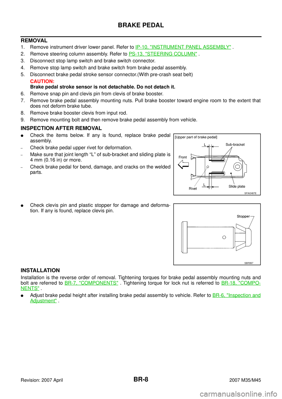
�Check the items below. If any is found, replace brake pedal
assembly.
–Check brake pedal upper rivet for deformation.
–Make sure that joint length “L” of sub-bracket and sliding plate is
4 mm (0.16 in) or more.
–Check brake pedal for bend, damage, and cracks on the welded
parts.
�Check clevis pin and plastic stopper for damage and deforma-
tion. If any is found, replace clevis pin.
INSTALLATION
Installation is the reverse order of removal. Tightening torques for brake pedal assembly mounting nuts and
bolt are referred to BR-7, "
COMPONENTS" . Tightening torque for lock nut is referred to BR-18, "COMPO-
NENTS" .
�Adjust brake pedal height after installing brake pedal assembly to vehicle. Refer to BR-6, "Inspection and
Adjustment" .
SFIA2487E
SBR997
Page 1305 of 4647
![INFINITI M35 2007 Factory Service Manual BRC-4
[VDC/TCS/ABS]
PRECAUTIONS
Revision: 2007 April2007 M35/M45
Precautions for Brake ControlNFS000Q1
�Just after starting vehicle after ignition switch ON, brake pedal may vibrate or motor operating INFINITI M35 2007 Factory Service Manual BRC-4
[VDC/TCS/ABS]
PRECAUTIONS
Revision: 2007 April2007 M35/M45
Precautions for Brake ControlNFS000Q1
�Just after starting vehicle after ignition switch ON, brake pedal may vibrate or motor operating](/manual-img/42/57024/w960_57024-1304.png)
BRC-4
[VDC/TCS/ABS]
PRECAUTIONS
Revision: 2007 April2007 M35/M45
Precautions for Brake ControlNFS000Q1
�Just after starting vehicle after ignition switch ON, brake pedal may vibrate or motor operating noise may
be heard from engine compartment. This is normal condition.
�When an error is indicated by ABS or another warning lamp, collect all necessary information from cus-
tomer (what symptoms are present under what conditions) and check for simple causes before starting
diagnostic servicing. Besides electrical system inspection, check brake booster operation, brake fluid
level, and oil leaks.
�If tire size and type are used in an improper combination, or brake pads are not Genuine NISSAN parts,
stopping distance or steering stability may deteriorate.
�ABS might be out of order or malfunctions by putting a radio (wiring inclusive), an antenna and a lead-in
wire near the control unit.
�If aftermarket parts (car stereo, CD player, etc.) have been installed, check for incidents such as harness
pinches, open circuits, and improper wiring.
�VDC system may not operate normally or a VDC OFF indicator lamp or SLIP indicator lamp may light.
–When replacing the following parts with parts other than genuine parts or making modifications: Suspen-
sion-related parts (shock absorber, spring, bushing, etc.), tires, wheels (other than specified sizes), brake-
related parts (pad, rotor, caliper, etc.), engine-related parts (muffler, ECM, etc.) and body reinforcement-
related parts (roll bar, tower bar, etc.).
–When driving with worn or deteriorated suspension, tires and brake-related parts.
Page 1444 of 4647

COMBINATION METERS
DI-25
C
D
E
F
G
H
I
J
L
MA
B
DI
Revision: 2007 April2007 M35/M45
Fuel Gauge Pointer Fluctuates, Indicator Wrong Value or VariesNKS003UB
1. CHECK FUEL GAUGE FLUCTUATION
Test drive vehicle to see if gauge fluctuates only during driving or at the instant of stopping.
Does the indication value vary only during driving or at the instant of stopping?
YES >> The pointer fluctuation may be caused by fuel level change in the fuel tank. Condition is normal.
NO >> Ask the customer about the situation when the symptom occurs in detail, and perform the trouble
diagnosis.
Fuel Gauge Does Not Move to FULL PositionNKS003UC
1. QUESTION 1
Does it take a long time for the pointer to move to FULL position?
YES >> GO TO 2.
NO >> GO TO 3.
2. QUESTION 2
Was the vehicle fueled with the ignition switch ON?
YES >> Be sure to fuel the vehicle with the ignition switch OFF. Otherwise, it will take a long time to move
to FULL position because of the characteristic of the fuel gauge.
NO >> GO TO 3.
3. QUESTION 3
Is the vehicle parked on an incline?
YES >> Check the fuel level indication with vehicle on a level surface.
NO >> GO TO 4.
4. QUESTION 4
During driving, does the fuel gauge pointer move gradually toward EMPTY position?
YES >> Check the fuel level sensor unit. Refer to DI-26, "CHECK FUEL LEVEL SENSOR UNIT" .
NO >> The float arm may interfere or bind with any of the components in the fuel tank.
Page 1521 of 4647

DI-102
COMPASS
Revision: 2007 April2007 M35/M45
COMPASSPFP:24835
Precautions for CompassNKS004F2
NOTE:
�Do not install the ski rack, antenna, etc. which is attach to the vehicle with a magnet base. It affects the
operation of the compass.
�When cleaning the mirror, use a paper towel or similar material dampened with glass cleaner. Do not
spray glass cleaner directly on the mirror as it may cause the liquid cleaner to enter the mirror housing.
System DescriptionNKS004F3
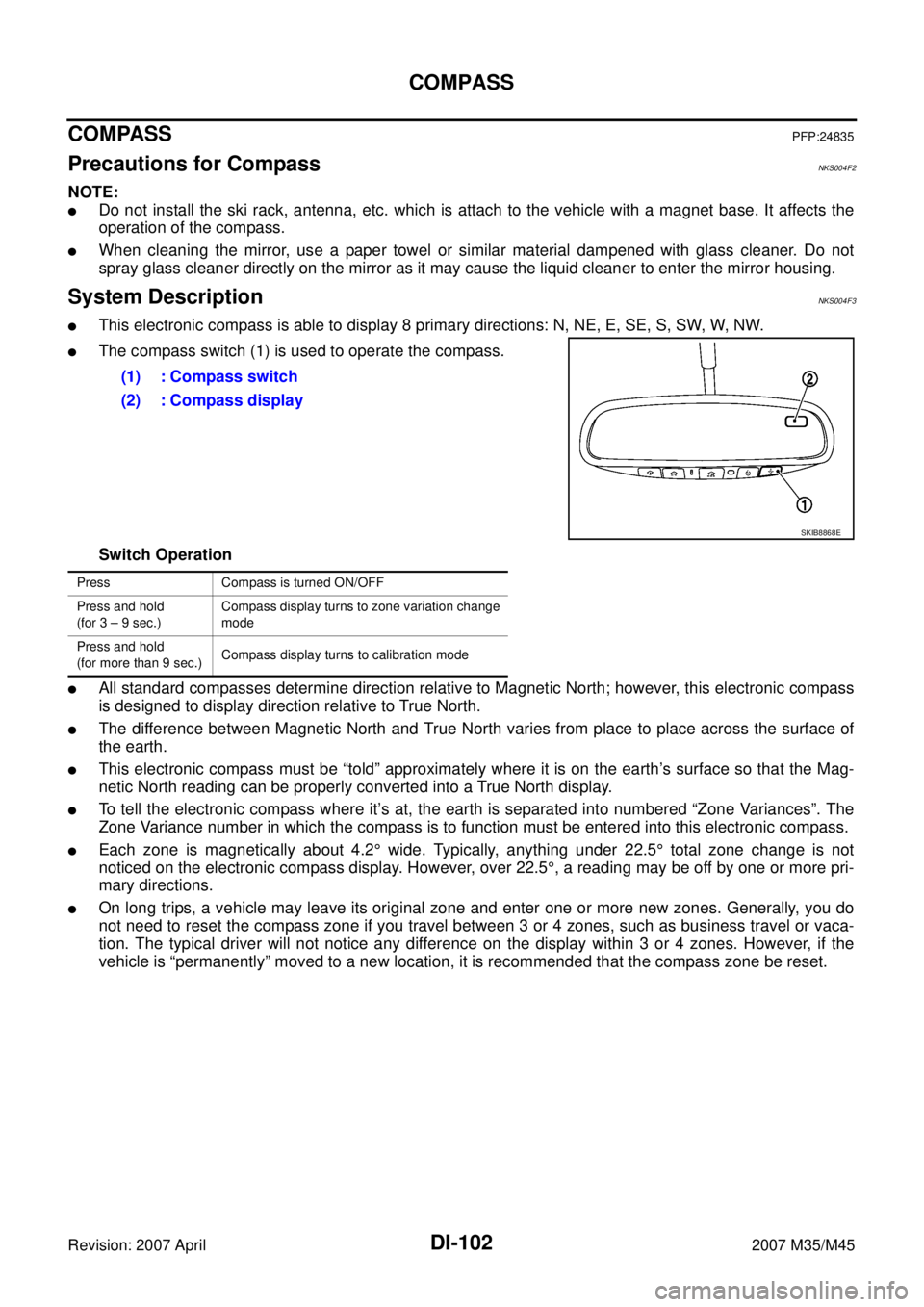
�This electronic compass is able to display 8 primary directions: N, NE, E, SE, S, SW, W, NW.
�The compass switch (1) is used to operate the compass.
Switch Operation
�All standard compasses determine direction relative to Magnetic North; however, this electronic compass
is designed to display direction relative to True North.
�The difference between Magnetic North and True North varies from place to place across the surface of
the earth.
�This electronic compass must be “told” approximately where it is on the earth’s surface so that the Mag-
netic North reading can be properly converted into a True North display.
�To tell the electronic compass where it’s at, the earth is separated into numbered “Zone Variances”. The
Zone Variance number in which the compass is to function must be entered into this electronic compass.
�Each zone is magnetically about 4.2° wide. Typically, anything under 22.5° total zone change is not
noticed on the electronic compass display. However, over 22.5°, a reading may be off by one or more pri-
mary directions.
�On long trips, a vehicle may leave its original zone and enter one or more new zones. Generally, you do
not need to reset the compass zone if you travel between 3 or 4 zones, such as business travel or vaca-
tion. The typical driver will not notice any difference on the display within 3 or 4 zones. However, if the
vehicle is “permanently” moved to a new location, it is recommended that the compass zone be reset.(1) : Compass switch
(2) : Compass display
SKIB8868E
Press Compass is turned ON/OFF
Press and hold
(for 3 – 9 sec.)Compass display turns to zone variation change
mode
Press and hold
(for more than 9 sec.)Compass display turns to calibration mode
Page 2984 of 4647

FRONT BUMPER
EI-13
C
D
E
F
G
H
J
K
L
MA
B
EI
Revision: 2007 April2007 M35/M45
Removal and Installation of Front Bumper GrilleNIS0024E
CAUTION:
Apply protection tape around outer circumference of front bumper grille (bumper fascia side).
REMOVAL
1. Disengage plastic pawls from vehicle inside using a plastic spatula.
2. While pulling the grille frontward, unlock the turn fastener around right end of the grille using a screw-
driver.
3. Insert a shop cloth to inside of front bumper grille as shown in
the figure, and then disengage lower plastic pawls by pulling
front bumper grille toward vehicle front.
4. Hold fog lamp opening of front bumper grille by hand as shown
in the figure, and then pull front bumper grille out toward vehicle
front by disengaging plastic pawls of both ends.
NOTE:
Plastic clips of both ends are engaged strongly. Strong power is
necessary to disengage them.
INSTALLATION
Install in reverse order of removal.
1. Bumper fascia assembly 2. Front bumper grille
PIIB4588E
PIIB4363J
PIIB4364J
Page 2986 of 4647

REAR BUMPER
EI-15
C
D
E
F
G
H
J
K
L
MA
B
EI
Revision: 2007 April2007 M35/M45
REMOVAL
1. Fully open trunk lid assembly.
2. Remove trunk floor carpet, trunk side box assembly, trunk rear plate, and trunk side finisher. Refer to EI-
56, "TRUNK ROOM TRIM & TRUNK LID FINISHER" .
3. Remove rear combination lamp (LH/RH). Refer to LT- 2 6 5 , "
Removal and Installation" .
4. Remove clips of rear combination lamp lower. (Figure to illustration B)
5. Remove clips of bumper fascia lower side.
6. Remove screws of bumper fascia left/right side. (Figure to illustration C)
7. Remove bumper fascia left/right bolt from trunk room inside. (Figure to illustration A)
8. Remove clip and bumper clamp from bumper fascia upper side, and then pull out bumper fascia toward
rear of vehicle. (Figure to illustration D)
9. Remove bumper fascia assembly.
CAUTION:
When removing bumper fascia, 2 workers are required so as to prevent it from dropping.
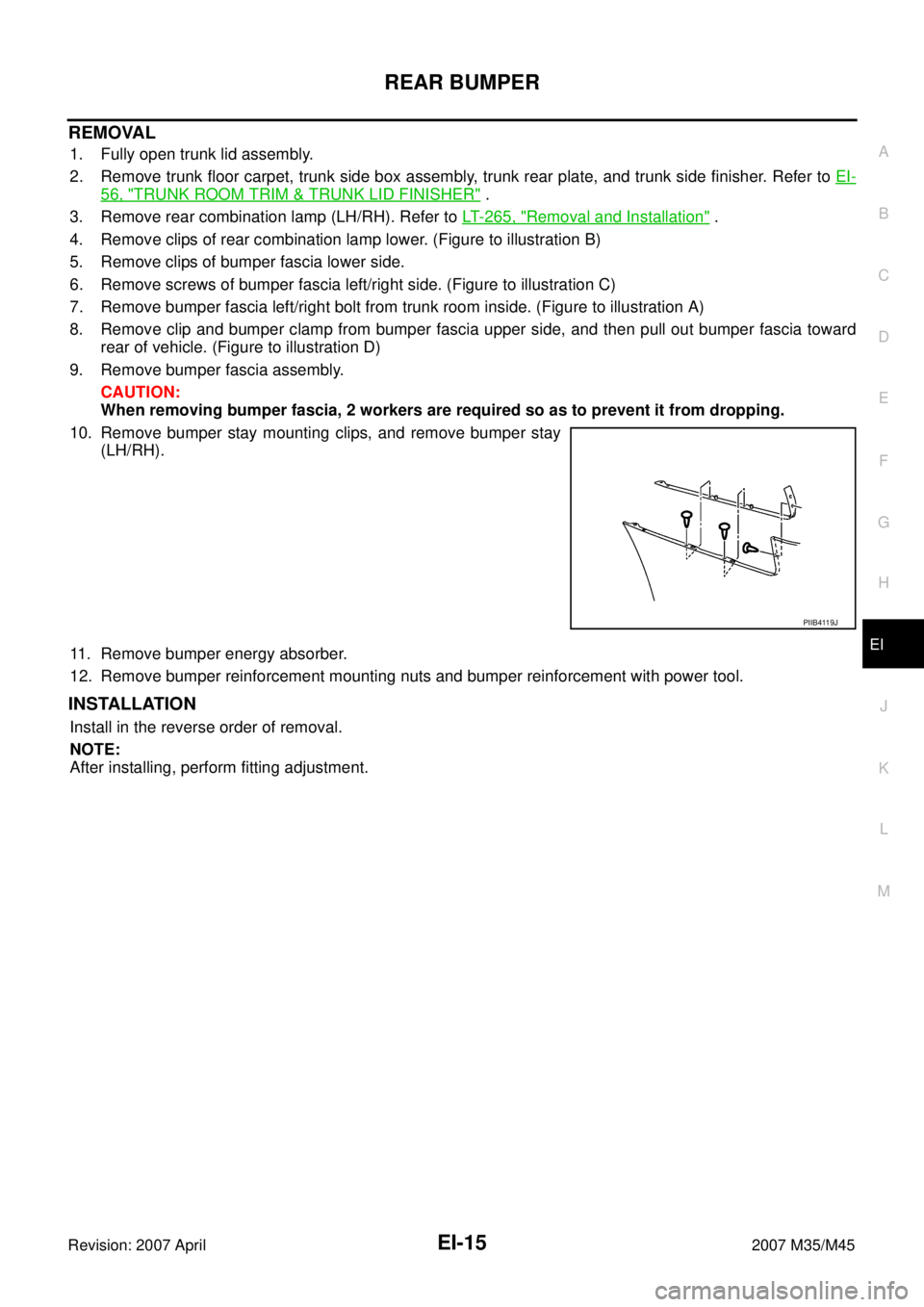
10. Remove bumper stay mounting clips, and remove bumper stay
(LH/RH).
11. Remove bumper energy absorber.
12. Remove bumper reinforcement mounting nuts and bumper reinforcement with power tool.
INSTALLATION
Install in the reverse order of removal.
NOTE:
After installing, perform fitting adjustment.
PIIB4119J
Page 2987 of 4647
EI-16
FRONT GRILLE
Revision: 2007 April2007 M35/M45
FRONT GRILLEPFP:62310
Removal and InstallationNIS0024G
CAUTION:
Apply protection tape around outer circumference of front grille (bumper fascia side).
REMOVAL
1. Fully open hood assembly.
2. Remove plastic clip from upper surface of the grille.
3. Remove plastic clip from front bumper upper side (convex part).
4. Pull front grille frontward. Disengage upper side plastic clip joint from back of front grille using pliers. (Fig-
ure to illustration A.)
5. Pull front grille out toward vehicle front. (Figure to illustration B.)
NOTE:
Plastic clips of front grille lower are engaged strongly. Strong power is necessary to disengage them. (When it
is not easy to disengage them, disengage the joint of lower side clip using a screwdriver while pulling the front
grille frontward.)
INSTALLATION
Install in the reverse order of removal.
1. Front grille
PIIB4647E
Page 3006 of 4647

DOOR FINISHER
EI-35
C
D
E
F
G
H
J
K
L
MA
B
EI
Revision: 2007 April2007 M35/M45
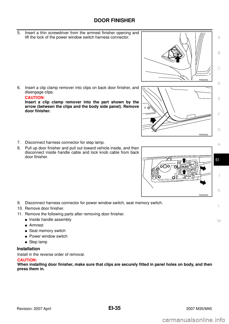
5. Insert a thin screwdriver from the armrest finisher opening and
lift the lock of the power window switch harness connector.
6. Insert a clip clamp remover into clips on back door finisher, and
disengage clips.
CAUTION:
Insert a clip clamp remover into the part shown by the
arrow (between the clips and the body side panel). Remove
door finisher.
7. Disconnect harness connector for step lamp.
8. Pull up door finisher and pull out toward vehicle inside, and then
disconnect inside handle cable and lock knob cable from back
door finisher.
9. Disconnect harness connector for power window switch, seat memory switch.
10. Remove door finisher.
11. Remove the following parts after removing door finisher.
�Inside handle assembly
�Armrest
�Seat memory switch
�Power window switch
�Ste p l am p
Installation
Install in the reverse order of removal.
CAUTION:
When installing door finisher, make sure that clips are securely fitted in panel holes on body, and then
press them in.
PIIB4936E
PIIB4932E
PIIB4933E