Page 3261 of 4647
GW-62
FRONT DOOR GLASS AND REGULATOR
Revision: 2007 April2007 M35/M45
5. While holding the door glass, raise it at the rear end to pull the
glass out of the sash toward the inside of the door.
Installation
Install in the reverse order of removal.
REGULATOR ASSEMBLY
Removal
1. Remove the front door finisher. Refer to EI-34, "DOOR FINISHER" .
2. Operate the power window main switch to raise/lower the door
window until the glass mounting bolts can be seen.
3. Remove the glass mounting bolts.
4. Raise up the door glass and hold with a suction lifter A.
5. Remove the mounting bolts, and remove the module assembly.
6. Disconnect the harness connector for the module assembly, and unclip the harness from the inside.
Installation
Install in the reverse order of removal.
SIIA1779J
PIIB3288J
PIIB3510J
Page 3491 of 4647
LT-40
HEADLAMP (FOR USA) - CONVENTIONAL TYPE -
Revision: 2007 April2007 M35/M45
Removal and InstallationNKS003OI
REMOVAL
1. Disconnect the battery cable from the negative terminal.
2. Remove front bumper. Refer to EI-11, "
Removal and Installation" .
3. Remove front bumper retainer (upper). Refer to EI-11, "
Removal and Installation" .
4. Remove front bumper clips. Refer to EI-11, "
Removal and Installation" .
5. Remove headlamp mounting bolts and nuts.
6. Remove plastic bumper bracket, then pull headlamp toward vehicle front, disconnect connector, and
remove headlamp.
INSTALLATION
Note the following, and installation is the reverse order of removal.
NOTE:
After installation, perform aiming adjustment. Refer to LT- 3 7 , "
Aiming Adjustment" .
1. Nut 2. Bolt 3. Headlamp assembly
4. Bolt
: N·m (kg-m, in-lb)
SKIB2958J
Headlamp mounting bolt : 5.5 N·m (0.56 kg-m, 49 in-lb)
Headlamp mounting nut : 5.5 N·m (0.56 kg-m, 49 in-lb)
Page 3526 of 4647
HEADLAMP (FOR USA) - XENON TYPE -
LT-75
C
D
E
F
G
H
I
J
L
MA
B
LT
Revision: 2007 April2007 M35/M45
Removal and InstallationNKS003P7
REMOVAL
1. Disconnect the battery cable from the negative terminal.
2. Remove front bumper. Refer to EI-11, "
Removal and Installation" .
3. Remove front bumper retainer (upper). Refer to EI-11, "
Removal and Installation" .
4. Remove front bumper clips. Refer to EI-11, "
Removal and Installation" .
5. Remove headlamp mounting bolts and nuts.
6. Remove plastic bumper bracket, then pull headlamp toward vehicle front, disconnect connector, and
remove headlamp.
INSTALLATION
Note the following, and installation is the reverse order of removal.
NOTE:
After installation, perform aiming adjustment. Refer to LT- 7 2 , "
Aiming Adjustment" .
1. Nut 2. Bolt 3. Headlamp assembly
4. Bolt
: N·m (kg-m, in-lb)
SKIB4155E
Headlamp mounting bolt : 5.5 N·m (0.56 kg-m, 49 in-lb)
Headlamp mounting nut : 5.5 N·m (0.56 kg-m, 49 in-lb)
Page 3681 of 4647
LT-230
LIGHTING AND TURN SIGNAL SWITCH
Revision: 2007 April2007 M35/M45
LIGHTING AND TURN SIGNAL SWITCHPFP:25540
Removal and InstallationNKS003S2
REMOVAL
1. Remove steering column lower cover. Refer to IP-10, "INSTRUMENT PANEL ASSEMBLY" .
2. While pressing pawls (A) in direction as shown in the figure, pull
lighting and turn signal switch (1) toward driver door and discon-
nect from the base.
INSTALLATION
Installation is the reverse order of removal.
Switch Circuit InspectionNKS003S3
Refer to LT- 2 3 9 , "Combination Switch Inspection" .
SKIB4186E
Page 3716 of 4647

REAR COMBINATION LAMP
LT-265
C
D
E
F
G
H
I
J
L
MA
B
LT
Revision: 2007 April2007 M35/M45
REAR COMBINATION LAMPPFP:26554
Bulb ReplacementNKS003SY
REAR TURN SIGNAL LAMP BULB, STOP/TAIL LAMP BULB
1. Remove trunk side finisher. Refer to EI-56, "Removal and Installation for Trunk Room Trim" .
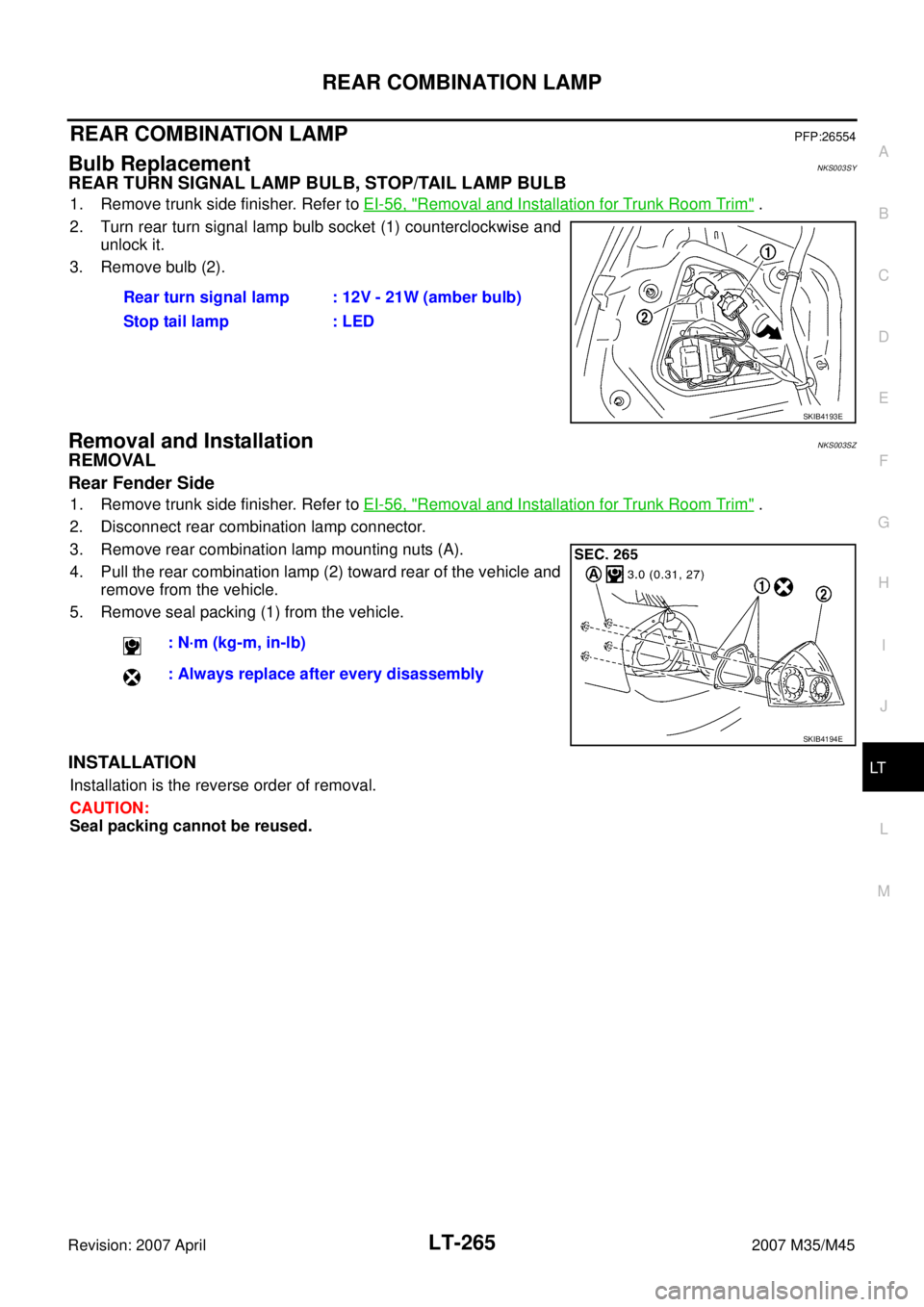
2. Turn rear turn signal lamp bulb socket (1) counterclockwise and
unlock it.
3. Remove bulb (2).
Removal and InstallationNKS003SZ
REMOVAL
Rear Fender Side
1. Remove trunk side finisher. Refer to EI-56, "Removal and Installation for Trunk Room Trim" .
2. Disconnect rear combination lamp connector.
3. Remove rear combination lamp mounting nuts (A).
4. Pull the rear combination lamp (2) toward rear of the vehicle and
remove from the vehicle.
5. Remove seal packing (1) from the vehicle.
INSTALLATION
Installation is the reverse order of removal.
CAUTION:
Seal packing cannot be reused.Rear turn signal lamp : 12V - 21W (amber bulb)
Stop tail lamp : LED
SKIB4193E
: N·m (kg-m, in-lb)
: Always replace after every disassembly
SKIB4194E
Page 3806 of 4647

PERIODIC MAINTENANCE
MA-7
C
D
E
F
G
H
I
J
K
MA
B
MA
Revision: 2007 April2007 M35/M45
PERIODIC MAINTENANCEPFP:00026
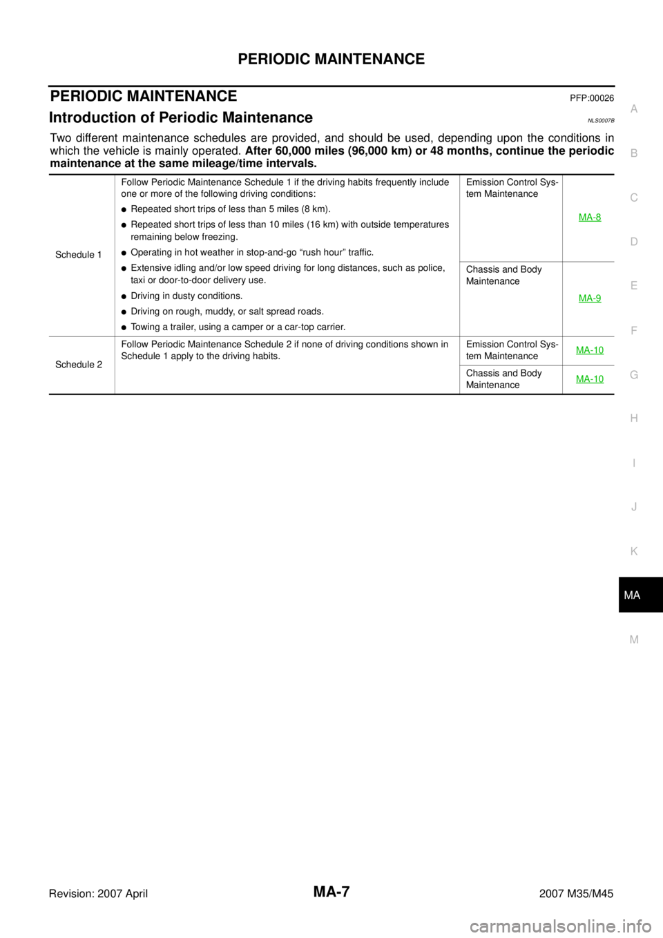
Introduction of Periodic MaintenanceNLS0007B
Two different maintenance schedules are provided, and should be used, depending upon the conditions in
which the vehicle is mainly operated. After 60,000 miles (96,000 km) or 48 months, continue the periodic
maintenance at the same mileage/time intervals.
Schedule 1Follow Periodic Maintenance Schedule 1 if the driving habits frequently include
one or more of the following driving conditions:
�Repeated short trips of less than 5 miles (8 km).
�Repeated short trips of less than 10 miles (16 km) with outside temperatures
remaining below freezing.
�Operating in hot weather in stop-and-go “rush hour” traffic.
�Extensive idling and/or low speed driving for long distances, such as police,
taxi or door-to-door delivery use.
�Driving in dusty conditions.
�Driving on rough, muddy, or salt spread roads.
�Towing a trailer, using a camper or a car-top carrier.Emission Control Sys-
tem Maintenance
MA-8
Chassis and Body
Maintenance
MA-9
Schedule 2Follow Periodic Maintenance Schedule 2 if none of driving conditions shown in
Schedule 1 apply to the driving habits.Emission Control Sys-
tem MaintenanceMA-10Chassis and Body
MaintenanceMA-10
Page 3808 of 4647

PERIODIC MAINTENANCE
MA-9
C
D
E
F
G
H
I
J
K
MA
B
MA
Revision: 2007 April2007 M35/M45
(2) If operating mainly in dusty conditions, more frequent maintenance may be required.
(3) Maintenance-free item. For service procedures, refer to FL section.
(4) After 60,000 miles (96,000 km) or 48 months, replace every 30,000 miles (48,000 km) or 24 months.
(5) If valve noise increases, inspect valve clearance.
* Maintenance items and intervals with “*” are recommended by INFINITI for reliable vehicle operation. The owner need not perform
such maintenance in order to maintain the emission warranty or manufacturer recall liability. Other maintenance items and intervals are
required.
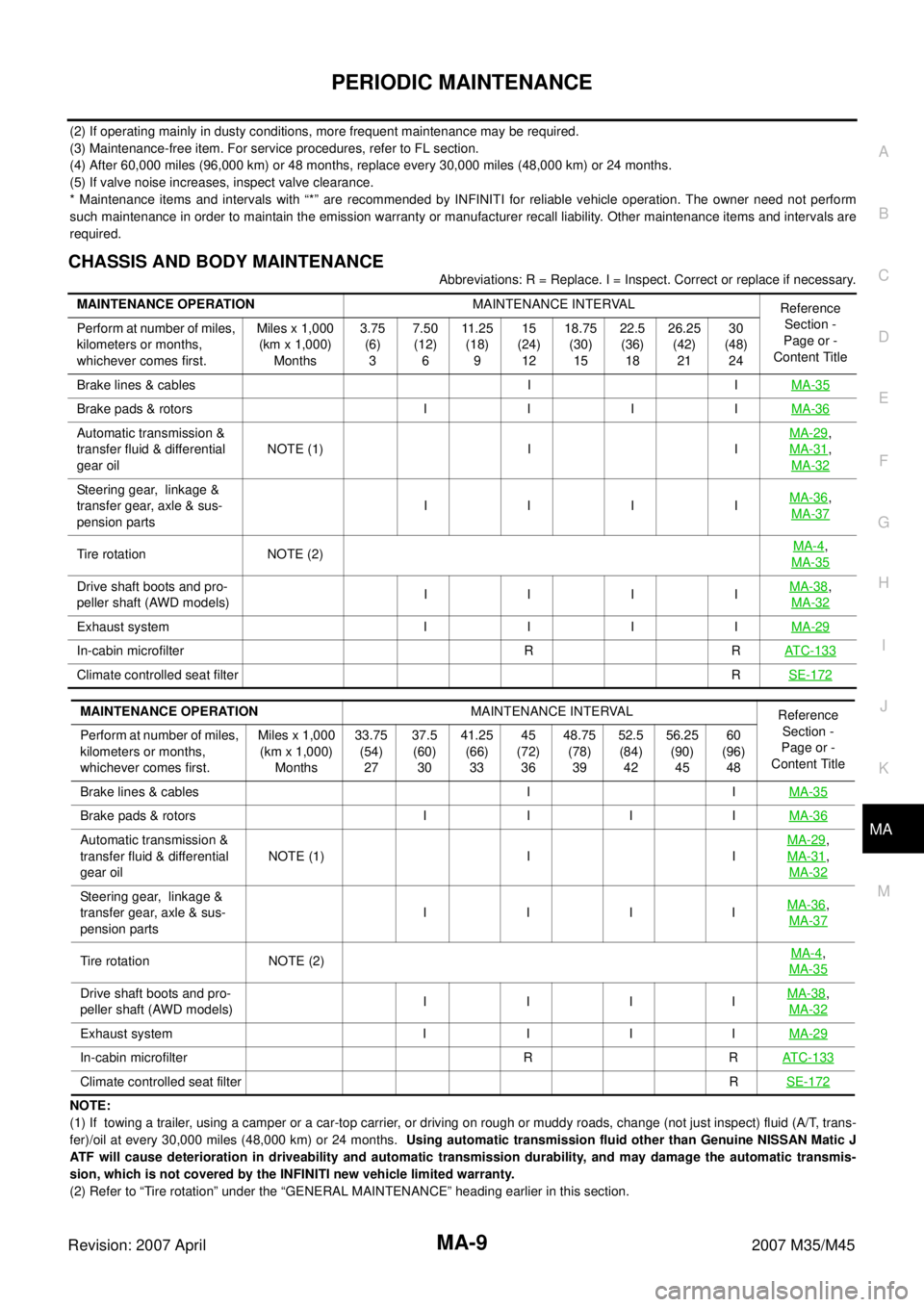
CHASSIS AND BODY MAINTENANCE
Abbreviations: R = Replace. I = Inspect. Correct or replace if necessary.
NOTE:
(1) If towing a trailer, using a camper or a car-top carrier, or driving on rough or muddy roads, change (not just inspect) fluid (A/T, trans-
fer)/oil at every 30,000 miles (48,000 km) or 24 months. Using automatic transmission fluid other than Genuine NISSAN Matic J
ATF will cause deterioration in driveability and automatic transmission durability, and may damage the automatic transmis-
sion, which is not covered by the INFINITI new vehicle limited warranty.
(2) Refer to “Tire rotation” under the “GENERAL MAINTENANCE” heading earlier in this section.MAINTENANCE OPERATIONMAINTENANCE INTERVAL
Reference
Section -
Page or -
Content Title Perform at number of miles,
kilometers or months,
whichever comes first.Miles x 1,000
(km x 1,000)
Months3.75
(6)
37.50
(12)
611 . 2 5
(18)
915
(24)
1218.75
(30)
1522.5
(36)
1826.25
(42)
2130
(48)
24
Brake lines & cables I IMA-35
Brake pads & rotors I I I IMA-36
Automatic transmission &
transfer fluid & differential
gear oilNOTE (1) I IMA-29,
MA-31
,
MA-32
Steering gear, linkage &
transfer gear, axle & sus-
pension partsIIIIMA-36,
MA-37
Tire rotation NOTE (2)MA-4,
MA-35
Drive shaft boots and pro-
peller shaft (AWD models) IIIIMA-38,
MA-32
Exhaust system I I I IMA-29
In-cabin microfilter R RAT C - 1 3 3
Climate controlled seat filterRSE-172
MAINTENANCE OPERATIONMAINTENANCE INTERVAL
Reference
Section -
Page or -
Content Title Perform at number of miles,
kilometers or months,
whichever comes first.Miles x 1,000
(km x 1,000)
Months33.75
(54)
2737.5
(60)
3041.25
(66)
3345
(72)
3648.75
(78)
3952.5
(84)
4256.25
(90)
4560
(96)
48
Brake lines & cables I IMA-35
Brake pads & rotors I I I IMA-36
Automatic transmission &
transfer fluid & differential
gear oilNOTE (1) I IMA-29,
MA-31
,
MA-32
Steering gear, linkage &
transfer gear, axle & sus-
pension partsI IIIMA-36,
MA-37
Tire rotation NOTE (2)MA-4,
MA-35
Drive shaft boots and pro-
peller shaft (AWD models)I IIIMA-38,
MA-32
Exhaust system I I I IMA-29
In-cabin microfilter R RAT C - 1 3 3
Climate controlled seat filterRSE-172
Page 3882 of 4647
IPDM E/R (INTELLIGENT POWER DISTRIBUTION MODULE ENGINE ROOM)
PG-31
C
D
E
F
G
H
I
J
L
MA
B
PG
Revision: 2007 April2007 M35/M45
Removal and Installation of IPDM E/RNKS004EC
: Vehicle front
REMOVAL
1. Remove cowl top cover (RH). Refer to EI-18, "COWL TOP" .
2. Disengage pawls (A) on both side of IPDM E/R cover B (1),
remove IPDM E/R cover A (2).
3. While pushing pawl (A) on backside of IPDM E/R cover B (1)
toward vehicle front to unlock, lift up IPDM E/R (2).
4. Disengage pawls on both side of IPDM E/R (1), remove IPDM E/
R cover B.
5. Remove harness connector from IPDM E/R (1) and remove
IPDM E/R (1).
INSTALLATION
Installation is the reverse order of removal.
SKIB4109E
SKIB4110E
SKIB4111E