Page 4448 of 4647
![INFINITI M35 2007 Factory Service Manual TROUBLE DIAGNOSIS
STC-9
[EPS]
C
D
E
F
H
I
J
K
L
MA
B
STC
Revision: 2007 April2007 M35/M45
For Fast and Accurate Trouble DiagnosisNGS000E1
Check the following items with the vehicle stopped
�Is air pre](/manual-img/42/57024/w960_57024-4447.png "INFINITI M35 2007 Factory Service Manual TROUBLE DIAGNOSIS
STC-9
[EPS]
C
D
E
F
H
I
J
K
L
MA
B
STC
Revision: 2007 April2007 M35/M45
For Fast and Accurate Trouble DiagnosisNGS000E1
Check the following items with the vehicle stopped
�Is air pre")
TROUBLE DIAGNOSIS
STC-9
[EPS]
C
D
E
F
H
I
J
K
L
MA
B
STC
Revision: 2007 April2007 M35/M45
For Fast and Accurate Trouble DiagnosisNGS000E1
Check the following items with the vehicle stopped
�Is air pressure and size of tires proper?
�Is the specified part used for the steering wheel?
�Is control unit a genuine part?
�Are there any fluid leakage from steering gear assembly, power steering oil pump, and hydraulic pipes,
etc? Refer to PS-8, "
Checking Fluid Leakage" .
�Is the fluid level proper? Refer to PS-8, "Checking Fluid Level" .
�Is the wheel alignment adjusted properly? Refer to FSU-6, "Wheel Alignment Inspection" (2WD), FSU-24,
"Wheel Alignment Inspection" (AWD).
�Are there any damage or modification to suspension or body resulting in increased weight or altered
ground clearance?
�Check each link installation condition of suspension and axle.
�Check each connector connection condition.
Check the following items while driving the vehicle
�Check conditions when the malfunction occurred (5W 1H).
�Is the engine condition normal?
Basic InspectionNGS000E2
POWER SUPPLY CIRCUIT TERMINAL LOOSENESS AND BATTERY
Check battery terminals for looseness on both positive and negative ones and ground connection. Also make
sure that battery voltage does not drop.
Inspection: Power Steering Control Unit Power Supply Circuit and GroundNGS000E3
1. CHECK POWER STEERING CONTROL UNIT CONNECTOR
Turn ignition switch OFF, disconnect power steering control unit harness connector, and check terminal for
deformation, disconnection, looseness, etc.
OK or NG
OK >> GO TO 2.
NG >> Connector terminal connection is loose, damaged, open, or shorted. Repair or replace the termi-
nal.
2. CHECK POWER STEERING CONTROL UNIT GROUND CIRCUIT
Disconnect power steering control unit harness connector M8, and
then check continuity between power steering control unit harness
connector M8 and ground.
OK or NG
OK >> GO TO 3.
NG >> Ground circuit open or shorted. Repair or replace any
inoperative parts. Terminal 2 – Ground : Continuity exist.
SGIA1231E
Page 4452 of 4647
![INFINITI M35 2007 Factory Service Manual REAR ACTIVE STEER
STC-13
[RAS]
C
D
E
F
H
I
J
K
L
MA
B
STC
Revision: 2007 April2007 M35/M45
[RAS]REAR ACTIVE STEERPFP:55705
Removal and InstallationNGS000E5
COMPONENTS
REMOVAL
1. Remove coil spring. Re](/manual-img/42/57024/w960_57024-4451.png "INFINITI M35 2007 Factory Service Manual REAR ACTIVE STEER
STC-13
[RAS]
C
D
E
F
H
I
J
K
L
MA
B
STC
Revision: 2007 April2007 M35/M45
[RAS]REAR ACTIVE STEERPFP:55705
Removal and InstallationNGS000E5
COMPONENTS
REMOVAL
1. Remove coil spring. Re")
REAR ACTIVE STEER
STC-13
[RAS]
C
D
E
F
H
I
J
K
L
MA
B
STC
Revision: 2007 April2007 M35/M45
[RAS]REAR ACTIVE STEERPFP:55705
Removal and InstallationNGS000E5
COMPONENTS
REMOVAL
1. Remove coil spring. Refer to RSU-16, "REAR LOWER LINK & COIL SPRING" .
2. Disconnect harness connector from RAS actuator assembly and rear suspension member.
3. Remove fixing bolts and nuts of RAS actuator assembly (1), and
then remove RAS actuator assembly (1) from rear suspension
member.
INSTALLATION
�Installation is the reverse order of removal. For tightening torque, refer to STC-13, "COMPONENTS" .
�When installing RAS actuator assembly to rear suspension member, check the mounting surfaces of RAS
actuator assembly and rear suspension member for oil, dirt, sand, or other foreign materials.
�To perform the neutral position adjustment. Refer to STC-14, "Neutral Position Adjustment" .
1. Rear lower link 2. Decenter cam 3. RAS actuator assembly
Refer to GI-11, "
Components" , for the symbols in the figure.
SGIA1238E
SGIA1239E
Page 4471 of 4647
![INFINITI M35 2007 Factory Service Manual STC-32
[RAS]
TROUBLE DIAGNOSIS
Revision: 2007 April2007 M35/M45
For Fast and Accurate Trouble DiagnosisNGS000EN
Check the following items with the vehicle stopped
�Is air pressure and size of tires pr](/manual-img/42/57024/w960_57024-4470.png "INFINITI M35 2007 Factory Service Manual STC-32
[RAS]
TROUBLE DIAGNOSIS
Revision: 2007 April2007 M35/M45
For Fast and Accurate Trouble DiagnosisNGS000EN
Check the following items with the vehicle stopped
�Is air pressure and size of tires pr")
STC-32
[RAS]
TROUBLE DIAGNOSIS
Revision: 2007 April2007 M35/M45
For Fast and Accurate Trouble DiagnosisNGS000EN
Check the following items with the vehicle stopped
�Is air pressure and size of tires proper?
�Is the specified part used for the steering wheel?
�Is control unit a genuine part?
�Are there any fluid leakage from steering gear assembly, power steering oil pump, and hydraulic pipes,
etc? Refer to PS-8, "
Checking Fluid Leakage" .
�Is the fluid level proper? Refer to PS-8, "Checking Fluid Level" .
�Is the wheel alignment is adjusted properly? Refer to FSU-6, "Wheel Alignment Inspection" (2WD), FSU-
24, "Wheel Alignment Inspection" (AWD).
�Are there any damage or modification to suspension or body resulting in increased weight or altered
ground clearance?
�Check each link installation condition of suspension and axle.
�Is the battery voltage proper?
�Check each connector connection condition.
Check the following items while driving the vehicle
�Conditions when the error occurred (5W 1H).
�Is the engine is normal?
Basic InspectionNGS000EO
BASIC INSPECTION 1: POWER SUPPLY CIRCUIT TERMINAL LOOSENESS AND BATTERY
Check battery terminals for looseness on both positive and negative ones and ground connection. Also make
sure that battery voltage does not drop.
BASIC INSPECTION 2: RAS WARNING LAMP INSPECTION
1. Make sure RAS warning lamp turns on when ignition switch is turned ON.
�If it does not turn on, refer to STC-33, "Trouble Diagnosis Chart" .
2. Make sure that RAS warning lamp turns off when the engine is started after ignition switch is turned ON. If
it does not turn off, perform self-diagnosis. Refer to STC-28, "
SELF-DIAG RESULT MODE" .
3. Always erase DTC memory after completing self-diagnosis. Refer to STC-29, "
How to Erase Self-Diag-
nostic Results" .
BASIC INSPECTION 3: RAS CONTROL UNIT POWER SUPPLY CIRCUIT AND GROUND CIR-
CUIT INSPECTION
1. CHECK RAS CONTROL UNIT CONNECTOR
Turn ignition switch OFF, disconnect RAS control unit harness connector, and check terminal for deformation,
disconnection, looseness, etc.
OK or NG
OK >> GO TO 2.
NG >> Poor connection of connector terminal. Repair or replace the terminal.
2. CHECK RAS CONTROL UNIT GROUND CIRCUIT
1. Disconnect RAS control unit harness connector B476, and then
check continuity between RAS control unit harness connector
B476 and ground.
OK or NG
OK >> GO TO 3.
NG >> Ground circuit open or shorted. Repair or replace any
inoperative parts. Terminal 34 – Ground : Continuity should exit.
SGIA1244E
Page 4498 of 4647

TRANSFER FLUID
TF-9
C
E
F
G
H
I
J
K
L
MA
B
TF
Revision: 2007 April2007 M35/M45
TRANSFER FLUIDPFP:31001
ReplacementNDS000D9
DRAINING
1. Run the vehicle to warm up the transfer unit sufficiently.
2. Stop the engine, and remove the drain plug to drain the transfer
fluid.
CAUTION:
When draining fluid, protect exhaust tube flange with cover.
3. Apply sealant to drain plug. Install drain plug on transfer and
tighten to the specified torque. Refer to TF-45, "
COMPO-
NENTS" .
�Use Genuine Silicone RTV or equivalent. Refer to GI-47,
"Recommended Chemical Products and Sealants" .
CAUTION:
Remove old sealant adhering to mounting surfaces. Also
remove any moisture, oil, or foreign material adhering to application and mounting surfaces.
FILLING
1. Remove filler plug and add transfer fluid until fluid level reaches
the specified limit near filler plug mounting hole.
CAUTION:
Carefully fill the fluid. (Fill up for approx. 3 minutes.)
2. Leave the vehicle for 3 minutes, and check the fluid level again.
3. Set a new gasket onto filler plug and install it on transfer and
tighten to the specified torque. Refer to TF-45, "
COMPO-
NENTS" .
CAUTION:
Do not reuse gasket.
InspectionNDS000DA
FLUID LEAKAGE AND FLUID LEVEL
1. Check if fluid is leaking from transfer or around it.
2. Check fluid level from filler plug mounting hole as shown in the
figure.
CAUTION:
Never start engine while checking fluid level.
3. Before installing filler plug, set a new gasket. Install filler plug on
transfer and tighten to the specified torque. Refer to TF-45,
"COMPONENTS" .
CAUTION:
Do not reuse gasket.
SDIA2087E
Fluid capacity
: Approx. 1.25 (2-5/8 US pt, 2-1/4 lmp pt)
SDIA2028E
SDIA2028E
Page 4529 of 4647
TF-40
FRONT OIL SEAL
Revision: 2007 April2007 M35/M45
FRONT OIL SEALPFP:38189
Removal and InstallationNDS000E1
REMOVAL
1. Remove the drain plug to drain the transfer fluid. Refer to TF-9, "Replacement" .
2. Remove the front propeller shaft. Refer to PR-4, "
FRONT PROPELLER SHAFT" .
3. Remove front oil seal using a flat-bladed screwdriver.
CAUTION:
Be careful not to damage the front case and front drive
shaft.
INSTALLATION
1. Apply ATF to front oil seal, install it with a drift until the end face
of front case.
CAUTION:
�Do not reuse front oil seal.
�When installing, do not incline front oil seal.
2. Install front propeller shaft. Refer to PR-4, "
FRONT PROPEL-
LER SHAFT" .
3. Install transfer fluid, check fluid level and for fluid leakage. Refer
to TF-9, "
Inspection" .
SDIA1782E
Tool number : ST27862000 ( — )
SDIA1783E
Page 4531 of 4647
TF-42
REAR OIL SEAL
Revision: 2007 April2007 M35/M45
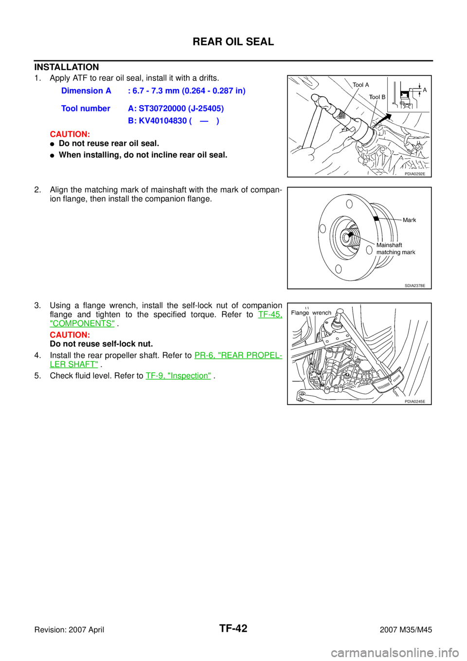
INSTALLATION
1. Apply ATF to rear oil seal, install it with a drifts.
CAUTION:
�Do not reuse rear oil seal.
�When installing, do not incline rear oil seal.
2. Align the matching mark of mainshaft with the mark of compan-
ion flange, then install the companion flange.
3. Using a flange wrench, install the self-lock nut of companion
flange and tighten to the specified torque. Refer to TF-45,
"COMPONENTS" .
CAUTION:
Do not reuse self-lock nut.
4. Install the rear propeller shaft. Refer to PR-6, "
REAR PROPEL-
LER SHAFT" .
5. Check fluid level. Refer to TF-9, "
Inspection" . Dimension A : 6.7 - 7.3 mm (0.264 - 0.287 in)
Tool number A: ST30720000 (J-25405)
B: KV40104830 ( — )
PDIA0292E
SDIA2378E
PDIA0245E