Page 3994 of 4647
STEERING COLUMN
PS-13
C
D
E
F
H
I
J
K
L
MA
B
PS
Revision: 2007 April2007 M35/M45
STEERING COLUMNPFP:48810
Removal and InstallationNGS000DA
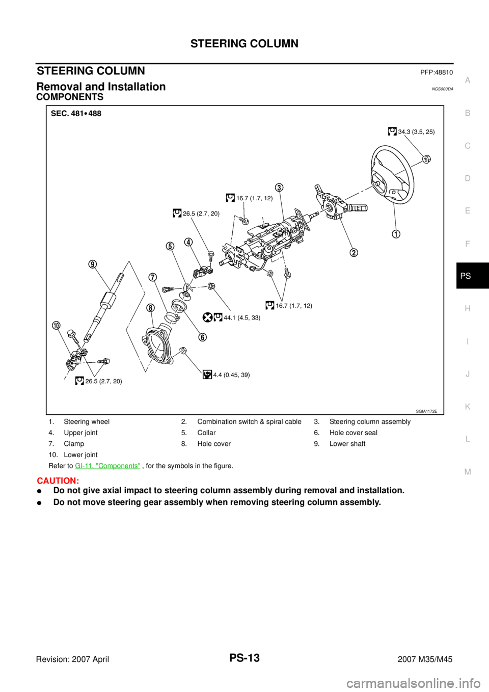
COMPONENTS
CAUTION:
�Do not give axial impact to steering column assembly during removal and installation.
�Do not move steering gear assembly when removing steering column assembly.
1. Steering wheel 2. Combination switch & spiral cable 3. Steering column assembly
4. Upper joint 5. Collar 6. Hole cover seal
7. Clamp 8. Hole cover 9. Lower shaft
10. Lower joint
Refer to GI-11, "
Components" , for the symbols in the figure.
SGIA1172E
Page 3996 of 4647
 with the marking position (B)
of gear housing assembly.
–Install slit part of")
STEERING COLUMN
PS-15
C
D
E
F
H
I
J
K
L
MA
B
PS
Revision: 2007 April2007 M35/M45
–Align rear cover cap projection (A) with the marking position (B)
of gear housing assembly.
–Install slit part of lower joint (C) aligning with the projection (A) of
rear cover cap (1). Make sure that the slit part of lower joint (C)
is aligned with projection (A) of rear cover cap (1) and the mark-
ing position (B) of gear housing assembly.
�Adjust neutral position of steering angle sensor. Refer to BRC-6,
"Adjustment of Steering Angle Sensor Neutral Position" .
REMOVAL OF STEERING COLUMN ASSEMBLY
1. Set vehicle to the straight-ahead position.
2. Remove driver air bag module. Refer to SRS-42, "
DRIVER AIR BAG MODULE" .
3. Remove steering wheel. Refer to PS-12, "
Removal and Installation" .
4. Remove steering column cover. Refer to IP-10, "
INSTRUMENT PANEL ASSEMBLY" .
5. Remove combination switch & spiral cable. Refer to SRS-44, "
SPIRAL CABLE" .
6. Remove instrument driver lower panel. Refer to IP-10, "
INSTRUMENT PANEL ASSEMBLY" .
7. Remove fixing bolts of knee protector (1), then remove knee
protector (1) from vehicle.
8. Remove low tire pressure warning control unit. Refer to WT-40,
"Low Tire Pressure Warning Control Unit" .
9. Disconnect each switch connectors installed to steering column
assembly, and then disconnect harness from steering column
assembly.
10. Remove fixing bolt of upper joint (1) (steering column assembly
side).
11. Remove steering column assembly mounting bolts and nut, then
remove steering column assembly from vehicle.
SGIA1175E
SGIA1176E
SGIA1182E
Page 3997 of 4647

PS-16
STEERING COLUMN
Revision: 2007 April2007 M35/M45
INSPECTION AFTER REMOVAL
�Check each part of steering column assembly for damage or other malfunctions. Replace if there are.
�Measure the length L as shown in the figure if vehicle has been
involved in a minor collision. Replace steering column assembly
if outside the standard.
�Measure steering column assembly rotating torque using preload gauge [SST: ST3127S000]. Replace
steering column assembly if outside the standard.
INSTALLATION OF STEERING COLUMN ASSEMBLY
�Installation is the reverse order of removal. For tightening torque, refer to PS-13, "COMPONENTS" .
�When installing upper joint, the angle which upper joint yoke (1)
forms with shaft center groove (A) should be at 90°.
�Adjust neutral position of steering angle sensor. Refer to BRC-6,
"Adjustment of Steering Angle Sensor Neutral Position" .
INSPECTION AFTER INSTALLATION
Make sure that steering wheel operates smoothly by turning several times from full left stop to full right stop.
SGIA1177E
Steering column length LTelescopic maximum 551 – 555 mm (21.69 – 21.85 in)
Telescopic minimum 591 – 595 mm (23.27 – 23.43 in)
Rotating torque : 0 – 0.2 N·m (0 – 0.02 kg-m, 0 – 1 in-lb)
SGIA1290E
Page 4000 of 4647

POWER STEERING GEAR AND LINKAGE
PS-19
C
D
E
F
H
I
J
K
L
MA
B
PS
Revision: 2007 April2007 M35/M45
POWER STEERING GEAR AND LINKAGEPFP:49001
Removal and InstallationNGS000DC
COMPONENTS
CAUTION:
Spiral cable may be cut if steering wheel turns while separating steering column assembly and steer-
ing gear assembly. Be sure to secure steering wheel using string to avoid turning.
REMOVAL
1. Set vehicle to the straight-ahead position.
2. Remove tires from vehicle with a power tool.
3. Remove undercover from vehicle with a power tool.
4. Remove lower side fixing bolt of lower joint.
5. Remove cotter pin (1), and then loosen the nut.
6. Remove steering outer socket (2) from steering knuckle (3) so
as not to damage ball joint boot (4) using the ball joint remover
(suitable tool).
CAUTION:
Temporarily tighten the nut to prevent damage to threads
and to prevent the ball joint remover from suddenly coming
off.
7. Remove high and low pressure piping of hydraulic piping, and
then drain power steering fluid. Refer to PS-39, "
HYDRAULIC
LINE" .
1. Cotter pin 2. Steering gear assembly 3. Steering gear assembly
(AWD models)
Refer to GI-11, "
Components" , for the symbols in the figure.
SGIA1387E
SGIA0844E
SGIA1183E
Page 4001 of 4647

PS-20
POWER STEERING GEAR AND LINKAGE
Revision: 2007 April2007 M35/M45
8. Remove steering hydraulic piping bracket from front suspension member. Refer to PS-39, "HYDRAULIC
LINE" .
9. Remove power steering solenoid valve harness connector. Refer to PS-21, "
COMPONENTS" .
10. Remove rack stay (2WD) or front cross bar (AWD). Refer to FSU-8, "
Components" , FSU-26, "Compo-
nents" .
11. Remove mounting bolts and nuts of steering gear assembly, and then remove steering gear assembly
from vehicle.
INSTALLATION
Installation is the reverse order of removal. For tightening torque, refer to PS-19, "COMPONENTS" .
�When installing lower joint to steering gear assembly, follow the procedure listed below.
–Set rack of steering gear in the neutral position.
NOTE:
To get the neutral position of rack, turn gear-sub assembly and measure the distance of inner socket, and
then measure the intermediate position of the distance.
–Align rear cover cap projection (A) with the marking position (B)
of gear housing assembly.
–Install slit part of lower joint (C) aligning with the projection (A) of
rear cover cap (1). Make sure that the slit part of lower joint (C)
is aligned with both the projection (A) of rear cover cap (1) and
the marking position (B) of gear housing assembly.
�After installation, bleed air from the steering hydraulic system.
Refer to PS-8, "
Air Bleeding Hydraulic System" .
�Perform final tightening of nuts and bolts on each part under
unladen conditions with tires on level ground when removing
steering gear assembly. Check wheel alignment. Refer to FSU-
6, "Wheel Alignment Inspection" , FSU-24, "Wheel Alignment
Inspection" .
�Adjust neutral position of steering angle sensor after checking wheel alignment. Refer to BRC-6, "Adjust-
ment of Steering Angle Sensor Neutral Position" .
INSPECTION AFTER INSTALLATION
Make sure that steering wheel operates smoothly by turning several times from full left stop to full right stop.
SGIA1175E
Page 4026 of 4647

PS-45
C
D
E
F
H
I
J
K
L
MA
B
PS
Revision: 2007 April2007 M35/M45
SERVICE DATA AND SPECIFICATIONS (SDS)PFP:00030
Steering WheelNGS000DM
Steering AngleNGS000DN
Stee")
SERVICE DATA AND SPECIFICATIONS (SDS)
PS-45
C
D
E
F
H
I
J
K
L
MA
B
PS
Revision: 2007 April2007 M35/M45
SERVICE DATA AND SPECIFICATIONS (SDS)PFP:00030
Steering WheelNGS000DM
Steering AngleNGS000DN
Steering ColumnNGS000DO
STEERING COLUMN LENGTH
TILT AND TELESCOPIC MECHANISM OPERATING RANGE
Steering wheel axial end play 0 mm (0 in)
Steering wheel play 0 – 35 mm (0 – 1.38 in)
Steering wheel turning force 7.45 N·m (0.76 kg-m, 66 in-lb)
Drive type2WD AWD
Tire size 245/45R18 245/40R19 245/45R18
Inner wheel
Degree minute (Decimal degree)Minimum 36°20′ (36.3°)39°45′ (39.8°)
Nominal 39°20′ (39.3°)42°45′ (42.8°)
Maximum 40°20′ (40.3°)43°45′ (43.8°)
Outer wheel
Degree minute (Decimal degree)Nominal 33°25′ (33.4°)33°20′ (33.3°)32°30′ (32.5°)
Steering column length LTelescopic maximum 551 – 555 mm (21.69 – 21.85 in)
Telescopic minimum 591 – 595 mm (23.27 – 23.43 in)
SGIA1177E
Tilt mechanism operating range L137.5 mm (1.476 in)
Telescopic mechanism operating range L
240 mm (1.57 in)
SGIA1179E
Page 4028 of 4647

RAX-1
REAR AXLE
D DRIVELINE/AXLE
CONTENTS
C
E
F
G
H
I
J
K
L
M
SECTION RAX
A
B
RAX
Revision: 2007 April2007 M35/M45
REAR AXLE
PRECAUTIONS .......................................................... 2
Caution ..................................................................... 2
PREPARATION ........................................................... 3
Special Service Tools [SST] ..................................... 3
Commercial Service Tools ........................................ 3
NOISE, VIBRATION AND HARSHNESS (NVH)
TROUBLESHOOTING ................................................ 4
NVH Troubleshooting Chart ..................................... 4
WHEEL HUB .............................................................. 5
On-Vehicle Inspection .............................................. 5
WHEEL BEARING INSPECTION ......................... 5
Removal and Installation .......................................... 5
COMPONENT ....................................................... 5
REMOVAL ............................................................. 5
INSPECTION AFTER REMOVAL ......................... 6
INSTALLATION ..................................................... 6REAR DRIVE SHAFT ................................................. 8
Removal and Installation .......................................... 8
COMPONENT ....................................................... 8
REMOVAL ............................................................. 8
INSPECTION AFTER REMOVAL ......................... 8
INSTALLATION ..................................................... 9
Disassembly and Assembly ...................................... 9
COMPONENT ....................................................... 9
DISASSEMBLY ..................................................... 9
INSPECTION AFTER DISASSEMBLY ................ 10
ASSEMBLY ......................................................... 11
SERVICE DATA AND SPECIFICATIONS (SDS) ...... 14
Wheel Bearing ........................................................ 14
Drive Shaft (VQ35DE model) ................................. 14
Drive Shaft (VK45DE model) .................................. 14
Page 4030 of 4647
PREPARATION
RAX-3
C
E
F
G
H
I
J
K
L
MA
B
RAX
Revision: 2007 April2007 M35/M45
PREPARATIONPFP:00002
Special Service Tools [SST]NDS000FN
The actual shapes of Kent-Moore tools may differ from those of special service tools illustrated here.
Commercial Service ToolsNDS000FO
Tool number
(Kent-Moore No.)
Tool nameDescription
KV38100500
(—)
Drift
a: 80 mm (3.15 in) dia.
b: 60 mm (2.36 in) dia.Installing drive shaft plug
KV38102200
(—)
Drift
a: 90 mm (3.54 in) dia.
b: 31 mm (1.22 in) dia.Installing drive shaft plug
ZZA0701D
ZZA0920D
Tool nameDescription
Power tool
�Removing wheel nuts
�Removing brake caliper assembly
�Removing suspension links
�Removing drive shaft
PBIC0190E
![INFINITI M35 2007 Factory Service Manual PREPARATION
RAX-3
C
E
F
G
H
I
J
K
L
MA
B
RAX
Revision: 2007 April2007 M35/M45
PREPARATIONPFP:00002
Special Service Tools [SST]NDS000FN
The actual shapes of Kent-Moore tools may differ from those of sp](/manual-img/42/57024/w960_57024-4029.png "INFINITI M35 2007 Factory Service Manual PREPARATION
RAX-3
C
E
F
G
H
I
J
K
L
MA
B
RAX
Revision: 2007 April2007 M35/M45
PREPARATIONPFP:00002
Special Service Tools [SST]NDS000FN
The actual shapes of Kent-Moore tools may differ from those of sp")