Page 1473 of 4647
DI-54
WARNING LAMPS
Revision: 2007 April2007 M35/M45
4. CHECK OIL PRESSURE SWITCH CIRCUIT
1. Turn ignition switch OFF.
2. Disconnect IPDM E/R connector.
3. Check continuity between IPDM E/R harness connector and
ground.
OK or NG
OK >> Replace IPDM E/R. Refer to PG-31, "Removal and
Installation of IPDM E/R" .
NG >> Repair harness or connector.
5. CHECK IPDM E/R (CONSULT-II)
Perform self-diagnosis of IPDM E/R. Refer to PG-20, "
CONSULT-II Function (IPDM E/R)" .
Self
-diagnostic results content
No malfunction detected>> Replace combination meter.
Malfunction detected>> Check applicable parts, and repair or replace corresponding parts.
Electrical Component InspectionNKS003UU
OIL PRESSURE SWITCH
Check continuity between oil pressure switch and ground.
IPDM E/R connector Terminal
GroundContinuity
E9 52 No
PKIB7659E
Condition
Oil pressure [kPa (kg/cm2 , psi)]Continuity
Engine stopped Less than 29 (0.3, 4) Yes
Engine running More than 29 (0.3, 4) No
ELF0044D
Page 1491 of 4647

DI-72
WARNING CHIME
Revision: 2007 April2007 M35/M45
Front Door Switch (Driver Side) Signal InspectionNKS003VA
1. CHECK BCM INPUT SIGNAL
With CONSULT-ll
1. Select “BCM” on CONSULT-II.
2. With “DATA MONITOR” of “BUZZER”, confirm “DOOR SW-DR”
when the driver side door is opened/closed.
Without CONSULT-ll
Check voltage between BCM harness connector and ground.
OK or NG
OK >> Front door switch (driver side) signal is OK. Return to
DI-70, "
SYMPTOM CHART" .
NG >> GO TO 2.
2. CHECK FRONT DOOR SWITCH (DRIVER SIDE) CIRCUIT
1. Turn ignition switch OFF.
2. Disconnect BCM connector and front door switch (driver side)
connector.
3. Check continuity between BCM harness connector (A) and front
door switch (driver side) harness connector (B).
4. Check continuity between BCM harness connector (A) and
ground.
OK or NG
OK >> GO TO 3.
NG >> Repair harness or connector.
3. CHECK FRONT DOOR SWITCH (DRIVER SIDE)
Check front door switch (driver side). Refer to DI-74, "
FRONT DOOR SWITCH (DRIVER SIDE)" .
OK or NG
OK >> Replace BCM. Refer to BCS-15, "Removal and Installation of BCM" .
NG >> Replace front door switch (driver side).“DOOR SW-DR”
When driver side door is opened : ON
When driver side door is closed : OFF
SEL502W
Te r m i n a l s
Condition
Voltage
(Approx.) (+)
(–)
BCM
connectorTerminal Driver side door:
M3 62 GroundOpen 0 V
Close 12 V
PKIB7662E
AB
Continuity
Connector Terminal Connector Terminal
M3 62 B11 2 Yes
A
GroundContinuity
Connector Terminal
M3 62 No
PKIB7663E
Page 1492 of 4647
WARNING CHIME
DI-73
C
D
E
F
G
H
I
J
L
MA
B
DI
Revision: 2007 April2007 M35/M45
Seat Belt Buckle Switch Signal InspectionNKS003VB
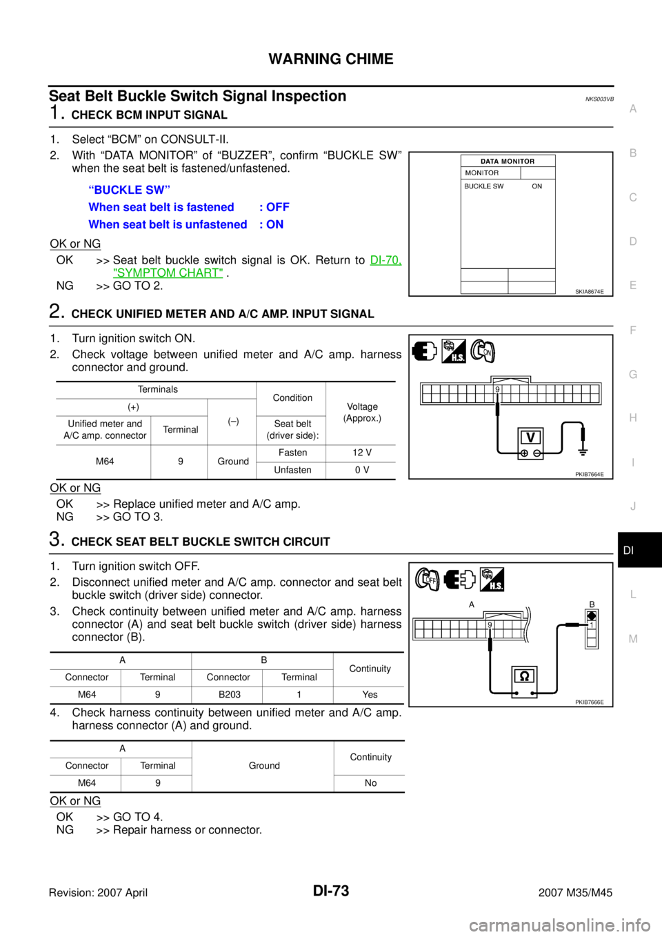
1. CHECK BCM INPUT SIGNAL
1. Select “BCM” on CONSULT-II.
2. With “DATA MONITOR” of “BUZZER”, confirm “BUCKLE SW”
when the seat belt is fastened/unfastened.
OK or NG
OK >> Seat belt buckle switch signal is OK. Return to DI-70,
"SYMPTOM CHART" .
NG >> GO TO 2.
2. CHECK UNIFIED METER AND A/C AMP. INPUT SIGNAL
1. Turn ignition switch ON.
2. Check voltage between unified meter and A/C amp. harness
connector and ground.
OK or NG
OK >> Replace unified meter and A/C amp.
NG >> GO TO 3.
3. CHECK SEAT BELT BUCKLE SWITCH CIRCUIT
1. Turn ignition switch OFF.
2. Disconnect unified meter and A/C amp. connector and seat belt
buckle switch (driver side) connector.
3. Check continuity between unified meter and A/C amp. harness
connector (A) and seat belt buckle switch (driver side) harness
connector (B).
4. Check harness continuity between unified meter and A/C amp.
harness connector (A) and ground.
OK or NG
OK >> GO TO 4.
NG >> Repair harness or connector.“BUCKLE SW”
When seat belt is fastened : OFF
When seat belt is unfastened : ON
SKIA8674E
Terminals
Condition
Voltage
(Approx.) (+)
(–)
Unified meter and
A/C amp. connectorTerminalSeat belt
(driver side):
M64 9 GroundFasten 12 V
Unfasten 0 V
PKIB7664E
AB
Continuity
Connector Terminal Connector Terminal
M64 9 B203 1 Yes
A
GroundContinuity
Connector Terminal
M64 9 No
PKIB7666E
Page 1511 of 4647

DI-92
LANE DEPARTURE WARNING SYSTEM
Revision: 2007 April2007 M35/M45
Trouble DiagnosisNKS003VN
HOW TO PERFORM TROUBLE DIAGNOSIS
1. Check the symptom and customer complaint.
2. Understand the outline of system. Refer to DI-75, "
System Description" .
3. Perform the preliminary inspection. Refer to DI-92, "
PRELIMINARY INSPECTION" .
4. Referring to symptom chart, make sure the cause of the malfunction and repair or replace applicable
parts. Refer to DI-93, "
SYMPTOM CHART" .
5. Erase DTC and perform self-diagnosis of LDW system again. Then perform LDW system running test.
Refer to DI-88, "
CONSULT-II Function (LDW)" and DI-77, "LDW SYSTEM RUNNING TEST" .
6. Does LDW system operate normally? If yes, GO TO 7. If no, GO TO 3.
7. INSPECTION END
PRELIMINARY INSPECTION
1. CHECK CAMERA LENS AND WINDSHIELD
Are camera lens and windshield contaminated with foreign materials?
YES >> Clean camera lens and windshield.
NO >> GO TO 2.
2. CHECK CAMERA UNIT INSTALLATION CONDITION
Check camera unit installation condition (installation position, properly tightened, a bent bracket).
OK or NG
OK >> GO TO 3.
NG >> Install camera unit properly, and adjust camera aiming. Refer to DI-78, "
Camera Aiming Adjust-
ment" .
3. CHECK VEHICLE HEIGHT
Check vehicle height. Refer to FSU-19, "
SERVICE DATA AND SPECIFICATIONS (SDS)" (2WD) or FSU-37,
"SERVICE DATA AND SPECIFICATIONS (SDS)" (AWD).
Is vehicle height appropriate?
OK >> GO TO 4.
NG >> Repair vehicle to appropriate height.
4. CHECK LDW CAMERA UNIT (CONSULT-II)
Perform self-diagnosis of LDW camera unit. Refer to DI-88, "
CONSULT-II Function (LDW)" .
Self
-diagnostic results content
No malfunction detected>>GO TO 5.
Malfunction detected>>Check applicable parts, and repair or replace corresponding parts.
5. CHECK COMBINATION METER
Check combination meter function.
Do speedometer and turn signal indicator function normally?
YES >> INSPECTION END
NO >> Check combination meter. Refer to DI-18, "
Trouble Diagnosis" .
Page 1515 of 4647
DI-96
LANE DEPARTURE WARNING SYSTEM
Revision: 2007 April2007 M35/M45
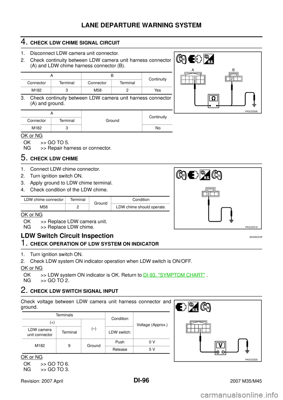
4. CHECK LDW CHIME SIGNAL CIRCUIT
1. Disconnect LDW camera unit connector.
2. Check continuity between LDW camera unit harness connector
(A) and LDW chime harness connector (B).
3. Check continuity between LDW camera unit harness connector
(A) and ground.
OK or NG
OK >> GO TO 5.
NG >> Repair harness or connector.
5. CHECK LDW CHIME
1. Connect LDW chime connector.
2. Turn ignition switch ON.
3. Apply ground to LDW chime terminal.
4. Check condition of the LDW chime.
OK or NG
OK >> Replace LDW camera unit.
NG >> Replace LDW chime.
LDW Switch Circuit InspectionNKS003VW
1. CHECK OPERATION OF LDW SYSTEM ON INDICATOR
1. Turn ignition switch ON.
2. Check LDW system ON indicator operation when LDW switch is ON/OFF.
OK or NG
OK >> LDW system ON indicator is OK. Return to DI-93, "SYMPTOM CHART" .
NG >> GO TO 2.
2. CHECK LDW SWITCH SIGNAL INPUT
Check voltage between LDW camera unit harness connector and
ground.
OK or NG
OK >> GO TO 6.
NG >> GO TO 3.
AB
Continuity
Connector Terminal Connector Terminal
M182 3 M58 2 Yes
A
GroundContinuity
Connector Terminal
M182 3 No
PKIC0250E
LDW chime connector Terminal
GroundCondition
M58 2 LDW chime should operate.
PKIC0251E
Terminals
Condition
Voltage (Approx.) (+)
(–)
LDW camera
unit connectorTerminal LDW switch:
M182 9 GroundPush 0 V
Release 5 V
PKIC0252E
Page 1517 of 4647
DI-98
LANE DEPARTURE WARNING SYSTEM
Revision: 2007 April2007 M35/M45
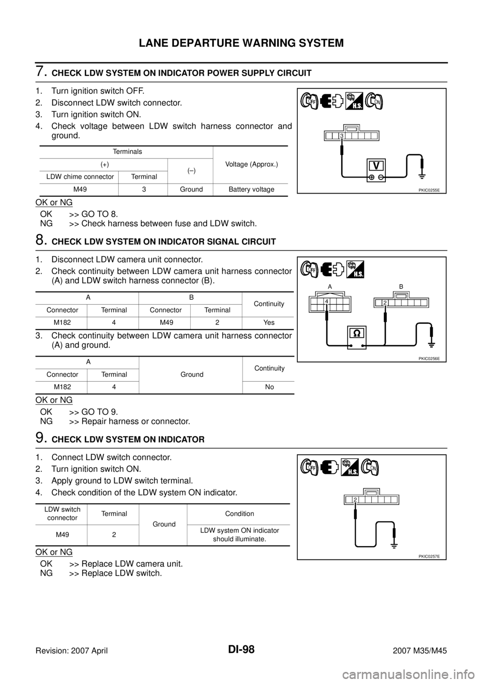
7. CHECK LDW SYSTEM ON INDICATOR POWER SUPPLY CIRCUIT
1. Turn ignition switch OFF.
2. Disconnect LDW switch connector.
3. Turn ignition switch ON.
4. Check voltage between LDW switch harness connector and
ground.
OK or NG
OK >> GO TO 8.
NG >> Check harness between fuse and LDW switch.
8. CHECK LDW SYSTEM ON INDICATOR SIGNAL CIRCUIT
1. Disconnect LDW camera unit connector.
2. Check continuity between LDW camera unit harness connector
(A) and LDW switch harness connector (B).
3. Check continuity between LDW camera unit harness connector
(A) and ground.
OK or NG
OK >> GO TO 9.
NG >> Repair harness or connector.
9. CHECK LDW SYSTEM ON INDICATOR
1. Connect LDW switch connector.
2. Turn ignition switch ON.
3. Apply ground to LDW switch terminal.
4. Check condition of the LDW system ON indicator.
OK or NG
OK >> Replace LDW camera unit.
NG >> Replace LDW switch.
Terminals
Voltage (Approx.) (+)
(–)
LDW chime connector Terminal
M49 3 Ground Battery voltage
PKIC0255E
AB
Continuity
Connector Terminal Connector Terminal
M1824 M492 Yes
A
GroundContinuity
Connector Terminal
M182 4 No
PKIC0256E
LDW switch
connectorTerminal
GroundCondition
M49 2 LDW system ON indicator
should illuminate.
PKIC0257E
Page 1518 of 4647
LANE DEPARTURE WARNING SYSTEM
DI-99
C
D
E
F
G
H
I
J
L
MA
B
DI
Revision: 2007 April2007 M35/M45
LDW Indicator Lamp Circuit InspectionNKS003VX
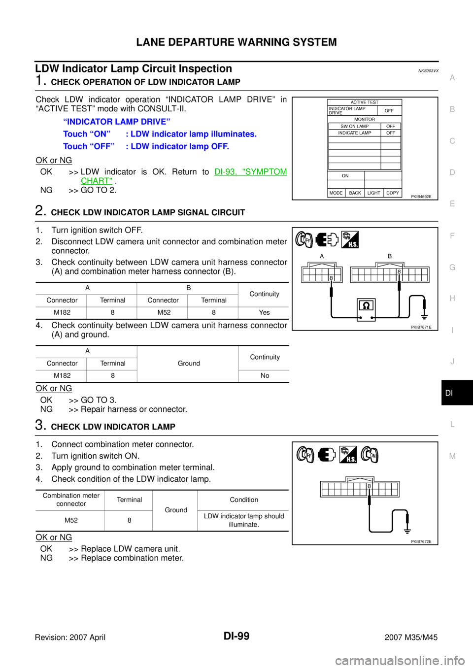
1. CHECK OPERATION OF LDW INDICATOR LAMP
Check LDW indicator operation “INDICATOR LAMP DRIVE” in
“ACTIVE TEST” mode with CONSULT-II.
OK or NG
OK >> LDW indicator is OK. Return to DI-93, "SYMPTOM
CHART" .
NG >> GO TO 2.
2. CHECK LDW INDICATOR LAMP SIGNAL CIRCUIT
1. Turn ignition switch OFF.
2. Disconnect LDW camera unit connector and combination meter
connector.
3. Check continuity between LDW camera unit harness connector
(A) and combination meter harness connector (B).
4. Check continuity between LDW camera unit harness connector
(A) and ground.
OK or NG
OK >> GO TO 3.
NG >> Repair harness or connector.
3. CHECK LDW INDICATOR LAMP
1. Connect combination meter connector.
2. Turn ignition switch ON.
3. Apply ground to combination meter terminal.
4. Check condition of the LDW indicator lamp.
OK or NG
OK >> Replace LDW camera unit.
NG >> Replace combination meter.“INDICATOR LAMP DRIVE”
Touch “ON” : LDW indicator lamp illuminates.
Touch “OFF” : LDW indicator lamp OFF.
PKIB4692E
AB
Continuity
Connector Terminal Connector Terminal
M1828 M528 Yes
A
GroundContinuity
Connector Terminal
M182 8 No
PKIB7671E
Combination meter
connectorTerminal
GroundCondition
M52 8LDW indicator lamp should
illuminate.
PKIB7672E
Page 1519 of 4647
DI-100
LANE DEPARTURE WARNING SYSTEM
Revision: 2007 April2007 M35/M45
Turn Signal Input InspectionNKS003VY
1. CHECK TURN SIGNAL INPUT
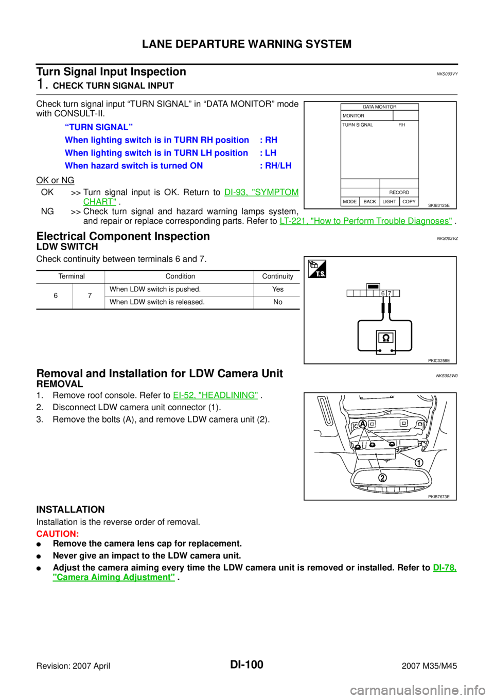
Check turn signal input “TURN SIGNAL” in “DATA MONITOR” mode
with CONSULT-II.
OK or NG
OK >> Turn signal input is OK. Return to DI-93, "SYMPTOM
CHART" .
NG >> Check turn signal and hazard warning lamps system,
and repair or replace corresponding parts. Refer to LT- 2 2 1 , "
How to Perform Trouble Diagnoses" .
Electrical Component InspectionNKS003VZ
LDW SWITCH
Check continuity between terminals 6 and 7.
Removal and Installation for LDW Camera UnitNKS003W0
REMOVAL
1. Remove roof console. Refer to EI-52, "HEADLINING" .
2. Disconnect LDW camera unit connector (1).
3. Remove the bolts (A), and remove LDW camera unit (2).
INSTALLATION
Installation is the reverse order of removal.
CAUTION:
�Remove the camera lens cap for replacement.
�Never give an impact to the LDW camera unit.
�Adjust the camera aiming every time the LDW camera unit is removed or installed. Refer to DI-78,
"Camera Aiming Adjustment" . “TURN SIGNAL”
When lighting switch is in TURN RH position : RH
When lighting switch is in TURN LH position : LH
When hazard switch is turned ON : RH/LH
SKIB3125E
Terminal Condition Continuity
67When LDW switch is pushed. Yes
When LDW switch is released. No
PKIC0258E
PKIB7673E